Summary of Contents for 21-100-001A
Page 1: ......
Page 2: ...2 ...
Page 3: ...3 Smartfind M5 Class A Inland AIS Installation and Maintenance Manual ...
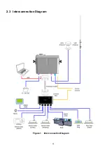
Page 12: ...12 2 3 Interconnection Diagram Figure 1 Interconnection Diagram ...
Page 81: ...81 6 MECHANICAL DIMENSIONS 6 1 Smartfind M5 Transponder Main Unit Front size mm Side size mm ...
Page 82: ...82 Back size mm Bottom size mm ...
Page 83: ...83 6 2 Junction Box 6 3 Extension Cable 6 4 Mounting Template not to scale 85 mm 55 mm 165 mm ...
Page 84: ...84 6 5 GPS Antenna 6 6 Pilot Plug 2 m 60 mm 40 mm 60 mm 80 mm 103 92 mm ...
Page 112: ...112 Note ...
Page 113: ...113 21 135 001N Issue 15 ...
Page 114: ......


