background image

Product Manual

PM ALR2-3

Group: 

Chiller

Date: 

August 2000

Supersedes:

 PM ALR2-2

© 2000 McQuay International

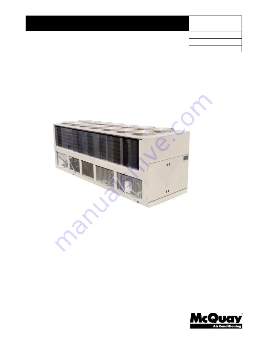
Air-Cooled Reciprocating Water Chillers

ALR 110F through 150F
110 to 150 Tons, 380 to 525 kW
R-22
60 Hertz

Summary of Contents for ALR 110F

Page 1: ...duct Manual PM ALR2 3 Group Chiller Date August 2000 Supersedes PM ALR2 2 2000 McQuay International Air Cooled Reciprocating Water Chillers ALR 110F through 150F 110 to 150 Tons 380 to 525 kW R 22 60 Hertz ...

Page 2: ... Installation and Application 30 Remote Evaporator 40 Dimensions Remote Evaporator 42 Optional Features 43 Specifications 45 McQuay is a registered trademark of McQuay International 1997 McQuay International Information covers McQuay International products at the time of publication and we reserve the right to make changes in design and construction at anytime without notice Our facility is ISO Ce...

Page 3: ...products and services that meet or exceed their expectations in terms of quality availability and competitiveness FEATURES BENEFITS Efficiency Cross circuit compressor unloading Copeland DISCUS compressors High efficiency lanced fin condenser coils Reliability Rugged compressor design Factory installed operating and safety controls Factory run tested with water hookup Code and agency approval Flex...

Page 4: ...t type with oversized bearing area that result in ultra low bearing loading The crankshaft is die forged high strength iron alloy with integral counterweights statically and dynamically balanced for smooth operation Connecting rods are lightweight aluminum with integral bearing surfaces on the crankshaft and piston ends Pistons are close grain cast iron with oil and compression rings Piston pins a...

Page 5: ...k water flow switch or both must be field installed to protect against evaporator freeze up under low water flow conditions Electrical Control Center Operating controls safety controls control transformer and motor starting equipment is factory wired operationally tested and ready for service All centrally located controls are in a weatherproof hinged control center with key locked doors Panel acc...

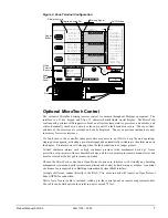
Page 6: ...lay can be mounted in the chiller control panel or remotely located providing monitoring and adjusting of certain functions Monitoring Monitor up to three setting or sensed values Monitor 18 different on off inputs Monitor alarm status via a flashing alarm light and flashing symbol Adjusting allows adjustment of any flashing set points three at a time typically set up so that the relationship betw...

Page 7: ...em temperatures pressures and safeties and will automatically shut down a circuit or the entire unit if a fault condition occurs The cause time and date of the occurrence is recorded and can be displayed The seven previous incidents are kept in memory for service reference If a fault occurs the controller takes preventive measures in an effort to keep the unit operating staging down capacity activ...

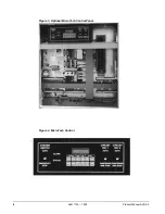
Page 8: ...8 ALR 110F 150F Product Manual ALR2 3 Figure 3 Optional MicroTech Control Panel Figure 4 MicroTech Control ...

Page 9: ...pressor kW input of 120 6 and a unit EER of 9 8 2 Use the following formula for water to calculate missing elements 24 gpm F T tons 3 Determine the evaporator pressure drop Using Figure 5 enter at 264 gpm and follow up to the ALR 110 line intersect Read horizontally to obtain an evaporator pressure drop of 14 3 feet of water Selection example using ethylene glycol Given R 22 105 tons minimum 95 F ...

Page 10: ...ature drops outside this range may affect the control system s capability to maintain acceptable control and are not recommended The maximum water temperature that can be circulated through the evaporator in a non operating mode is 100 F 37 8 C Table 1 Ethylene Glycol Freeze Point E G F C Capacity Power Flow PD 10 26 3 0 991 0 996 1 013 1 070 20 18 8 0 982 0 992 1 040 1 129 30 7 14 0 972 0 986 1 0...

Page 11: ...0 992 1 011 0 985 1 009 0 962 1 002 0 919 0 988 14 6 8 0 997 1 014 0 990 1 012 0 967 1 005 0 924 0 991 2000 feet 610 m 16 8 9 1 000 1 016 0 993 1 014 0 970 1 007 0 927 0 993 6 3 3 0 966 1 016 0 959 1 014 0 937 1 007 0 895 0 993 8 4 4 0 969 1 018 0 962 1 016 0 940 1 009 0 898 0 995 10 5 6 0 973 1 021 0 966 1 019 0 944 1 012 0 902 0 998 12 6 7 0 978 1 025 0 971 1 023 0 949 1 016 0 906 1 002 14 6 8 0...

Page 12: ...12 9 149 5 142 5 11 3 141 7 154 5 9 9 132 6 166 3 8 7 124 2 178 6 7 7 135F 50 0 164 0 131 9 13 2 155 8 144 6 11 5 147 2 156 7 10 1 138 4 169 2 8 9 129 7 181 7 7 8 40 0 145 9 129 9 11 6 138 1 141 1 10 3 130 3 152 1 9 0 121 9 163 1 8 0 114 5 173 9 7 0 42 0 149 9 131 7 11 8 142 7 143 3 10 5 134 6 154 6 9 2 126 4 166 1 8 1 118 4 177 4 7 1 44 0 155 4 133 4 12 3 147 3 145 5 10 8 139 7 157 1 9 6 130 7 16...

Page 13: ... 6 2 9 457 0 164 2 2 5 427 8 176 0 2 2 9 0 48 2 F 557 0 130 4 3 8 527 9 142 7 3 3 500 3 154 7 2 9 468 5 166 6 2 6 438 7 178 9 2 3 135F 10 0 50 0 F 576 9 131 9 3 9 547 8 144 6 3 4 517 7 156 7 3 0 486 7 169 2 2 6 456 1 181 7 2 3 5 0 41 0 F 520 1 130 8 3 4 493 9 142 2 3 0 465 9 153 3 2 7 436 7 164 6 2 4 409 6 175 6 2 1 6 0 42 8 F 534 9 132 3 3 5 508 5 144 2 3 1 480 6 155 6 2 7 450 6 167 2 2 4 422 0 1...

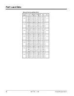
Page 14: ...5 00 30 8 24 1 15 3 100 00 129 6 161 0 9 7 130F 75 00 97 2 95 9 12 2 13 6 50 00 64 8 54 0 14 4 25 00 32 4 24 8 15 7 100 00 133 7 168 0 9 6 135F 75 00 100 3 100 3 12 0 13 4 50 00 66 8 55 3 14 5 25 00 33 4 28 2 14 2 100 00 139 7 174 8 9 6 140F 75 00 104 7 102 5 12 3 13 7 50 00 69 8 56 9 14 7 25 00 34 9 27 0 15 5 100 00 143 2 178 2 9 6 145F 75 00 107 5 104 4 12 4 13 5 50 00 71 6 61 3 14 0 25 00 35 9 ...

Page 15: ... Size Minimum Flow gpm l s Pressure Drop ft kPa Maximum Flow gpm l s Pressure Drop ft kPa 110 165 10 4 6 0 17 9 435 27 4 39 0 116 0 120 180 11 4 4 3 12 8 480 30 3 30 5 90 0 130 195 12 3 5 1 15 2 520 32 8 37 5 111 8 135 200 12 6 5 3 15 8 535 33 8 40 0 119 2 140 205 13 0 5 8 17 3 550 34 7 42 0 125 2 145 215 13 6 4 3 12 8 570 36 0 29 5 87 9 150 220 13 9 4 5 13 4 590 37 2 31 0 92 4 ...

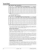
Page 16: ...particle displacement phenomena A vibrating body produces compression waves and as the waves are emitted from the vibrating body molecules are ultimately compressed These waves are transmitted through gases liquids or solids anything that is elastic or viscous The sound data provided in this section is presented with both sound pressure Q 1 and 30 feet from unit and sound power levels Sound power ...

Page 17: ...sound power r distance from unit in feet Q directionality factor The directionality factor Q is a dimensionless number that compensates for the type of sound reflection from the source For example a unit sitting on a flat roof or ground with no other reflective surfaces or attenuation due to grass snow etc between source and receiver Q 1 Figure 6 Q Definition Plan View Unit Located in Center Unifo...

Page 18: ... opposite the control box the compressor sound is blocked by the coil structure evaporator and naturally attenuated by distance as the compressors are located approximately the length of the unit away from this end The sound pressure levels at the end opposite the control box will be 4 dBA less than on the sides Figure 8 Sound Directionality Sound Pressure Levels Low Ambient Operation Air cooled u...

Page 19: ...or distance as noted above will decrease sound levels Sound levels can also be controlled by the installation of barrier walls To be effective as sound blockers walls must be solid with no open penetrations Sound tends to leak out of openings Block walls with filler material and slots on the side facing the unit are especially effective The wall should be about 10 feet high two feet higher than th...

Page 20: ...0 460 293 3 350 1 2 50 64 300 350 130F 575 60 210 3 4 0 1 2 00 51 225 250 208 626 6 400 2 2 50 64 700 700 230 590 6 350 2 2 50 64 700 700 460 302 3 350 1 2 50 64 350 350 135F 575 60 224 3 4 0 1 2 00 51 250 250 208 656 6 400 2 3 00 76 700 700 230 622 6 400 2 3 00 76 700 700 460 310 3 400 1 2 50 64 350 350 140F 575 60 236 3 250 1 2 50 64 250 250 208 656 6 400 2 3 00 76 700 700 230 622 6 400 2 3 00 7...

Page 21: ...0 38 175 175 137 3 1 0 1 1 50 38 175 175 130F 575 28 3 10 1 1 00 25 30 30 97 3 3 1 1 25 32 110 125 97 3 3 1 1 25 32 110 125 208 71 3 4 1 2 00 51 80 80 296 3 350 1 2 50 64 350 400 296 3 350 1 2 50 64 350 400 230 71 3 4 1 2 00 51 80 80 277 3 300 1 2 50 64 350 350 277 3 300 1 2 50 64 300 400 460 35 3 8 1 1 25 32 35 35 142 3 1 0 1 1 50 38 175 200 142 3 1 0 1 1 50 38 175 200 135F 575 28 3 10 1 1 00 25 ...

Page 22: ...2 8 12 10 7 297 297 297 297 195 195 195 195 130F 575 43 43 43 43 2 3 12 11 5 245 245 245 245 152 152 152 152 208 123 123 138 138 5 8 12 23 7 650 650 754 754 400 400 463 463 230 114 114 130 130 5 8 12 21 4 594 594 594 594 340 340 340 340 460 61 61 65 65 2 8 12 10 7 297 297 297 297 195 195 195 195 135F 575 43 43 49 49 2 3 12 11 5 245 245 245 245 152 152 152 152 208 138 138 138 138 5 8 12 23 7 754 75...

Page 23: ...5 1 qty 4 400 MCM 250 1qty 4 350 MCM 208 840 2 qty 1 0 600 MCM N A 230 840 2 qty 1 0 600 MCM N A 460 335 1 qty 4 400 MCM 400 1 qty 250 500 MCM 130F 575 335 1 qty 4 400 MCM 250 1qty 4 350 MCM 208 840 2 qty 1 0 600 MCM N A 230 840 2 qty 1 0 600 MCM N A 460 335 1 qty 4 400 MCM 400 1 qty 250 500 MCM 135F 575 335 1 qty 4 400 MCM 250 1qty 4 350 MCM 208 840 2 qty 1 0 600 MCM N A 230 840 2 qty 1 0 600 MCM...

Page 24: ...0 1 qty 12 2 0 130F 575 175 175 175 1 qty 12 2 0 1 qty 12 2 0 1 qty 12 2 0 208 175 335 335 1 qty 12 2 0 1 qty 4 400 MCM 1 qty 4 400 MCM 230 175 335 335 1 qty 12 2 0 1 qty 4 400 MCM 1 qty 4 400 MCM 460 175 175 175 1 qty 12 2 0 1 qty 12 2 0 1 qty 12 2 0 135F 575 175 175 175 1 qty 12 2 0 1 qty 12 2 0 1 qty 12 2 0 208 175 840 840 1 qty 12 2 0 2 qty 1 0 600 MCM 2 qty 1 0 600 MCM 230 175 840 840 1 qty 1...

Page 25: ...00 of all other loads in the circuit 9 The recommended power lead wire sizes are based on an ambient temperature of 86 F Ampacity correction factors must be applied for other ambient temperatures Refer to the National Electrical Code Handbook 10 The MCA may vary depending on options selected SpeedTrol totally enclosed fan motors Voltage Limitations Within 10 of nameplate rating Notes for Compresso...

Page 26: ...F 1 540 13 F2 COOLER HEATER COOLER HEATER SEPARTE 115V POW ERFORCOOLER HEATER SEE NOTE A SEE NOTE A 54 5 N OTE A IT MAY BE DE S IRABL E TO HAVE T HE UN IT CO OLER HE AT ER ON A S EPARATE DISCON NE CT S WITCH FROM T HE MAIN UN IT POWE R S UPPLY S O TH AT T HE U NIT MAY BE S HUT DOWN WITH O UT DE FE AT I N G TH E FRE EZ E PROTE CTIO N PROVIDED BY THE CO OLE R H EATE R T O AC CO MPL I S H T HIS REMOV...

Page 27: ...6 32 40 48 0 17 32 41 48 0 17 33 42 50 0 16 32 40 48 68 84 92 100 65 84 91 100 67 83 92 100 66 84 92 100 CONDENSERS HIGH EFFICIENCY FIN AND TUBE TYPE WITH INTEGRAL SUBCOOLING Coil Face Area Sq Ft 115 115 115 115 115 115 115 115 Coil Face Area M2 10 3 10 3 10 3 10 3 10 3 10 3 10 3 10 3 Finned Height x Finned Length In 80 x 208 80 x 208 80 x 208 80 x 208 80 x 208 80 x 208 80 x 208 80 x 208 Finned He...

Page 28: ... 33 42 50 0 17 33 42 50 0 15 32 40 48 67 83 92 100 67 83 92 100 68 84 92 100 CONDENSERS HIGH EFFICIENCY FIN AND TUBE TYPE WITH INTEGRAL SUBCOOLING Coil Face Area Sq Ft 115 115 115 115 115 115 Coil Face Area M2 10 3 10 3 10 3 10 3 10 3 10 3 Finned Height x Finned Length In 80 x 208 80 x 208 80 x 208 80 x 208 80 x 208 80 x 208 Finned Height x Finned Length mm 2032 x 5283 2032 x 5283 2032 x 5283 2032...

Page 29: ... 7 2405 17 5 445 16 3 414 30 7 780 97 0 2464 41 7 1059 36 0 914 102 2591 192 4877 12 135F 229 5809 8 203 2 94 7 2405 17 5 445 16 3 414 30 7 780 97 0 2464 41 7 1059 36 0 914 102 2591 192 4877 12 140F 229 5809 8 203 2 94 7 2405 17 5 445 16 3 414 30 7 780 97 0 2464 41 7 1059 36 0 914 102 2591 192 4877 12 145F 229 5809 8 203 2 94 8 2408 17 2 437 18 3 465 29 8 757 99 0 2515 41 7 1059 36 0 914 102 2591 ...

Page 30: ...ded Restricting airflow or allowing air recirculation will result in a decrease in unit performance and efficiency because discharge pressures are increased There must be no obstruction above the unit that would deflect discharge air downward where it could be recirculated back to the inlet of the condenser coil The condenser fans are propeller type and will not operate with ductwork on the fan ou...

Page 31: ...oTech control is proactive in response to off design conditions In the case of single or compounded influences restricting airflow to the unit the microprocessor will act to keep the compressor s running at reduced capacity rather than allowing a shut off on high discharge pressure The optional MicroTech control can be programmed to sequence the compressors in the most advantageous way For example...

Page 32: ...will increase compressor discharge pressure decreasing capacity and increasing power consumption Only the compressors connected to these coils will be affected Circuits opposite the wall are unaffected When close to a wall it is desirable to place chillers on the North or East side of them It is also desirable to have prevailing winds blowing parallel to the unit s long axis The worst case is to h...

Page 33: ...ase 1 Add the two adjustment factors together and apply to the unit located between the wall and the other unit Mounting units end to end will not necessitate adjusting performance Depending on the actual arrangement sufficient space must be left between the units for access to the control panel door opening and or evaporator tube removal See Clearance section of this guide for requirements for sp...

Page 34: ...side chillers 1 and 3 in this case are influenced by the middle unit only on their inside circuits Their adjustment factors will be the same as Case 2 All inside units only number 2 in this case are influenced on both sides and must be adjusted by the factors shown below Figure 17 Three or More Units Figure 18 Adjustment Factor ...

Page 35: ... or less than the unit height when mounted on its base support This is usually satisfactory for concealment The distance from the ends of the unit to the end walls should be sufficient for service opening control panel doors and pulling evaporator tubes as applicable If each side wall is different distance from the unit the distances can be averaged providing either wall is not more than 8 feet 2 ...

Page 36: ...th occur A solid wall surrounding a unit is substantially the same as a pit and the data presented here should be used Steel grating is sometimes used to cover a pit for safety considerations The grating material must provide abundant open area or serious recirculation problems will occur It would be prudent to have any pit installation reviewed by McQuay application engineers prior to installatio...

Page 37: ... the supply and return water lines Chilled water piping should be insulated to reduce heat loss and prevent condensation Chillers not running in the winter should have their water systems thoroughly drained to protect against freezing If the chiller operates year round or if the system is not drained for the winter the chilled water piping exposed to outdoor temperature should be protected against...

Page 38: ...ling load can change rapidly additional system water volume is needed A process example would be the cooling of hot metal objects The load would be very stable until the hot metal is dipped into the water tank Then the load would increase drastically For this type of application we recommend that the normal comfort cooling recommendation addressed above plus three minutes of ballast for every 10 q...

Page 39: ...ns to satisfy most ambient conditions Aluminum Fin Lanced slotted 16 fpi aluminum fin is the standard fin material It is used in non corrosive non abrasive applications Tubes are copper and completely covered by the fin shoulders on the face of the coil Copper Fin Optional copper fins are a solid ripple fin design 18 fpi Tubes are copper and completely covered by the fin shoulders on the face of t...

Page 40: ...for field installation and wiring The evaporator is equipped with entering and leaving chilled water temperature sensor wells The sensors are pre wired to the ALR unit with 30 foot long sensor leads that must be field connected to field furnished evaporator thermowells The leads can be field spliced up to 75 feet ALR units are shipped with a holding charge of refrigerant Field piping must be leak ...

Page 41: ...The refrigerant connections are located approximately where the refrigerant connections to the unit mounted evaporator are on a packaged chiller The remote evaporator dimensions are on Figure 24 Weights Weights for the remote evaporators are listed on the following dimension page Weights for the outdoor unit can be calculated by subtracting the evaporator weight from the total unit weight found in...

Page 42: ...DE350332801 34 128 1 4 40 0 934 423 635 288 34 15 4 34 15 4 120 140 CDE350332901 40 150 1 8 52 4 1127 510 758 343 45 20 4 45 20 4 145 150 CDE350281651 55 208 2 4 67 2 1464 663 943 427 57 25 8 57 25 8 Overall Dimensions in mm Dimensions ALR Model Length K Height A D J H B Conn G 110 94 6 2403 19 7 500 12 8 325 85 2 2164 6 4 163 11 0 279 5 152 120 140 95 5 2426 20 4 518 14 0 356 84 0 2134 6 8 173 12...

Page 43: ...on 2 phase loss with under over voltage protection and 3 phase loss with under over voltage protection and multiple LED indication of fault type 115 Volt Convenience Outlet The outlet is located in the main Control panel section Meets most code requirements for a convenience outlet located at or on the unit Multiple Point Wiring Connections Special that provides separate power blocks for each of t...

Page 44: ... field hook up of the water flow safety switch Unit Protective Base Frame Guards Optional factory installed base guards provide protection for the area under the coils on ground level installations Coil guards for fin protection are standard Copper Fin Condenser Coils Copper fin condenser coils are available as an option on all models Black Fin Coil Aluminum fin stock is precoated with a phenolic ...

Page 45: ... 1 03 SUBMITTALS A Submit shop drawings and product data in accordance with the specifications B Submittals shall include the following 1 Dimensioned plan and elevation view drawings required clearances and location of all field connections 2 Summary of all auxiliary utility requirements such as electricity water compressed air etc Summary shall indicate quality and quantity of each required utili...

Page 46: ...efects in material and workmanship within the above period excluding refrigerant PART 2 PRODUCTS 2 01 ACCEPTABLE MANUFACTURERS A McQuay International B Approved Equal 2 02 UNIT DESCRIPTION Provide and install as shown on the plans factory assembled factory charged and factory run tested air cooled reciprocating compressor packaged chillers in the quantity specified Each chiller shall consist of mu...

Page 47: ...s shall be removable It shall be insulated with 3 4 inch 19mm closed cell polyurethane insulation and be heated with an electric heater to provide freeze protection to 20 F 29 C ambient temperature The evaporator shall be designed inspected and stamped in accordance with ASME Code requirements C Condenser The condenser coils shall be 3 8 inch 10mm seamless copper tubes mechanically bonded into pla...

Page 48: ...ion points control interlock terminals and control system Power and starting components shall include factory fusing of fan motors and control circuit individual contactors for each fan motor solid state start timer solid state compressor three phase motor overload protection inherent fan motor overload protection and unit power terminal blocks for connection to remote disconnect switch Terminals ...

Page 49: ...Lead lag by manual selection or automatically by minimum circuit run hours 11 Discharge pressure control through intelligent cycling of condenser fans 12 Continuous diagnostic checks of unit operation to provide a pre alarm signal in advance of a shutdown allowing time for remedial action to be taken 2 05 OPTIONS AND ACCESSORIES The following options are to be included Part winding start Three pha...

Page 50: ...hiller in alignment on supports C Coordinate electrical installation with electrical contractor D Coordinate controls with control contractor E Provide all appurtenances required to insure a fully operational and functional chiller 3 02 START UP A Ensure proper charge of refrigerant and oil B Provide testing and starting of machine and instruct the Owner in its proper operation and maintenance ...

Page 51: ......

Page 52: ...Post Office Box 2510 Staunton Virginia 24402 2510 USA 800 432 1342 www mcquay com ...

Reviews: