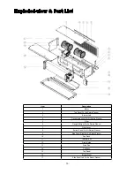
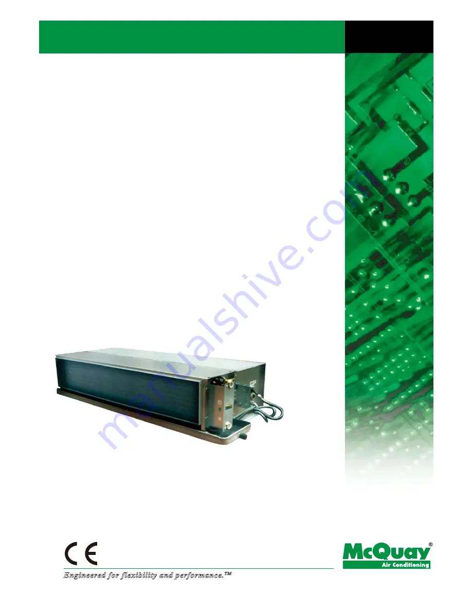
background image

Ceiling Concealed 

Chilled Water Fan Coil Unit

Models:  MCW200DA  MCW900DA


MCW300DA  MCW1000DA


MCW400DA  MCW1200DA


MCW500DA  MCW1400DA


MCW600DA  MCW1600DA


MCW800DA

Technical Manual

Engineered for flexibility and performance.

TM

MCW-DA-2009

Summary of Contents for MCW1000DA

Page 1: ...led Chilled Water Fan Coil Unit Models MCW200DA MCW900DA MCW300DA MCW1000DA MCW400DA MCW1200DA MCW500DA MCW1400DA MCW600DA MCW1600DA MCW800DA Technical Manual Engineered for flexibility and performance TM MCW DA 2009 ...

Page 2: ...l appearance of McQuay International products at the time of publication We reserve the right to change design and construction specifications at any time without notice Note Installation and maintenance are to be performed only by qualified personnel who are familiar with local codes and regulations and experienced with this type of equipment Caution Sharp edges and coil surfaces are a potential ...

Page 3: ...terial of Drain Pan A Coated Cold Rolled Steel S Stainless Steel Power Supply A 220 240V 1PH 50Hz F 8mm Nylon Filter G 25mm Nylon Filter H 25mm Aluminium Filter Back Rerurn Air Plenum With Bottom Removal Filter Pipe Connection R Right Hand L Left Hand Facing Air Flow 75Pa External Static Pressure Design Series DA 4 Rows and 2 Pipes Nominal Air Flow CFM McQuay Horizontal Ceiling Concealed Fan Coil ...

Page 4: ...r to meet even the most demanding customer requirements the new FCUs adopt the most reasonable and optimized water circuit design and utilize the National accredited thermal test room to guarantee both the perfect performance and a low chilled water pressure drop Extra High Air Flow Volume at High ESP These units can supply more air flow at high ESP 11 models of MCW DA cover an air flow range from...

Page 5: ...12 26887 33984 RATED POWER INPUT H W 84 101 116 148 165 297 299 309 507 603 665 M W 78 92 108 133 154 273 277 290 475 523 607 L W 58 69 92 110 133 225 232 250 407 428 529 RATED CURRENT INPUT H A 0 40 0 48 0 54 0 67 0 81 1 44 1 53 1 58 2 37 2 78 3 10 M A 0 36 0 42 0 49 0 62 0 71 1 25 1 28 1 34 2 17 2 46 2 78 L A 0 28 0 32 0 43 0 54 0 61 1 02 1 06 1 14 1 85 2 04 2 42 WATER FLOW RATE m3 h 0 16 0 22 0...

Page 6: ... POLES 4 COIL TYPE Seamless Copper Tube Mechanically Bonded To Corrugated Aluminum Fin TESTING PRESSURE Pressure Test 3 3mpa For 1 Minute Leakage Test 1 6mpa For 5 Minutes TUBE MATERIAL Copper DIAMETER mm 9 52 in 3 8 THICKNESS mm 0 3 in 0 012 FIN MATERIAL Hydrophilic Aluminum THICKNESS mm 0 11 in 0 0043 FACE AREA m2 0 09 0 12 0 14 0 16 0 18 0 24 0 26 0 30 0 30 0 33 0 41 ft2 141 185 217 242 273 377...

Page 7: ...3 45 8 43 4 29 9 20 5 49 6 M 30 8 40 0 41 6 46 1 42 1 29 2 18 3 49 2 30 2 40 5 41 7 46 0 42 1 29 0 17 5 49 2 L 31 5 37 5 39 3 43 5 38 8 25 4 15 1 46 6 29 9 38 1 39 8 44 2 40 3 26 9 15 6 47 4 800DA H 34 7 41 1 42 2 45 9 39 8 29 1 19 7 49 1 33 2 40 7 42 3 46 0 40 2 29 9 20 5 49 2 M 33 6 40 5 41 9 45 4 39 5 28 8 19 3 48 6 33 4 40 5 41 9 45 5 39 6 29 6 20 0 48 7 L 31 7 38 5 40 3 43 9 37 5 26 6 16 8 47...

Page 8: ... 5 14 5 7 17 4 88 0 68 13 MCW1000DA 75 24 18 5 5 14 5 7 91 5 48 0 75 11 MCW1200DA 75 24 18 5 5 14 5 9 96 6 77 0 83 11 MCW1400DA 75 24 18 5 5 14 5 10 43 7 84 0 98 15 MCW1600DA 75 24 18 5 5 14 5 13 00 9 97 1 23 20 Model ESP Entering air Temperature Water Temperature Cooling Capacity kw Water flow Water Pressure Drop Pa DB WB In Out Total Sensible m3 h kPa MCW200DA 50 26 7 19 4 7 2 15 6 2 33 1 47 0 2...

Page 9: ...480 600DA H 1167 1106 1038 963 923 882 794 699 M 1104 1044 978 906 869 830 748 660 L 865 828 782 726 694 660 585 501 800DA H 1662 1587 1506 1417 1369 1320 1216 1104 M 1592 1516 1433 1344 1296 1247 1144 1033 L 1318 1263 1200 1129 1090 1049 961 865 900DA H 1916 1830 1733 1623 1564 1502 1369 1223 M 1863 1778 1681 1573 1515 1453 1321 1178 L 1611 1534 1447 1348 1294 1238 1118 986 1000DA H 2047 1952 185...

Page 10: ...ERATING LIMITS Maximum water side pressure 16 Bars Minimum entering water temperature 3 Maximum entering water temperature 95 Minimum air inlet temperature 5 Maximum air inlet temperature 43 Power supply 220 240V 1Ph 50Hz ...

Page 11: ...10 Water Flow vs Pressure Drop Chart NOTE ALL SPECIFICATIONS ARE SUBJECTED TO CHANGE BY THE MANUFACTURER WITHOUT PRIOR NOTICE ...

Page 12: ...143 530 211 243 382 2 MCW500DA 997 772 807 789 842 860 151 143 530 211 243 382 2 MCW600DA 1097 872 907 889 942 960 151 143 530 211 243 382 2 MCW800DA 1427 1202 1237 1219 1272 1290 151 143 530 211 243 382 3 MCW900DA 1537 1302 1337 1359 1412 1420 151 143 530 211 243 382 4 MCW1000DA 1727 1502 1537 1519 1572 1580 151 143 530 211 243 382 4 MCW1200DA 1427 1202 1237 1219 1272 1290 201 194 600 266 297 413...

Page 13: ...e Department regulation Wiring Diagram NOTE FOR MCW DA SERIES H M L ARE CONNECTED TO SHF HF MF RESPECTIVELY MODEL MCW 200 1600 POWER SOURCE ORANGE N L MF LF SHF HF L M BROWN H YELLOW FAN BLACK FAN SPEED SWITCH NOTE MOTOR 1 BLACK FAN MOTOR CAPACITOR MOTOR CAPACITOR 2 BLACK FAN MOTOR BLACK FAN RED RED YELLOW BROWN ORANGE BLUE BLUE HF HIGH SPEED MF MEDIUM SPEED LF LOW SPEED SHF SUPER HIGH SPEED FIELD...

Page 14: ...ing 1 There must be enough space for unit installation and maintenance Please refer to the outline and dimensions and fig 1 for the minimum distance between the unit and obstacle 2 In case of installation in free blow the unit must be installed at a minimum height of 2 5m to avoid contact with the appliance 3 Please ensure enough space for piping connection and electrical wiring 4 Please make sure...

Page 15: ...e of the drain pipe is at least 1 50 Wiring 1 Wiring connection must be done according to the wiring diagram on the unit 2 The unit must be GROUNDED well 3 An appropriate strain relief device must be used to attach the power wires to the terminal box 4 A 7 8 hole is designed on the terminal box for field installation of the strain relief device 5 Field wiring must be complied with the national sec...

Page 16: ...p bottom For Air Return Plenum 5 Filter 6 Flange left right For Air Return Plenum 7 Filter Cover 8 Bottom Panel For Air Return Plenum 9 Side Panel Right For Air Return Plenum 10 Fan Deck 11 Terminal Box 12 Drain Guide 13 Drain Pan 14 Coil Assy 15 Top Panel 16 Blower Right 17 Side Panel Left For Air Return Plenum ...

Page 17: ...084066187 M03084066188 M03084066189 M03084066190 M03084066191 M03084066192 MODEL MCW900DA MCW1000DA MCW1200DA MCW1400DA MCW1600DA CLASS B MOTOR MOTOR 1 YSK150 4B6 M03034065204 YSK150 4B6 M03034065204 YSK240 4B8 M03034065206 YSK280 4B8 M03034065208 YSK240 4B8 M03034065206 MOTOR 2 YSK150 4B6 M03034065204 YSK150 4B6 M03034065204 YDK95 4B6 M03034065207 YDK125 4B6 M03034065209 YSK240 4B8 M03034065206 D...

Page 18: ...nsure more effective thermal and sound insulation together with fire proof safety 3 Casing Anti corrosion powder coating looks elegant and more endurable to erosive environment 4 Filter 25mm nylon filter and 25mm aluminum filter optional Different material filter meet various customer requirements 5 Motor Class F insulation motor provides reliable operation and suits harder applications Optional ...

Page 19: ...es slit type aluminum blue fins bonded to the tubes by mechanical expansion Each coil has a manual air vent and two Rc3 4 water pipe connections with a working pressure of 1 6MPa 3 Fan Direct driven centrifugal fan wheel has forward curved blades which are statically and dynamically balanced The fan housing and blades are constructed of high quality hot galvanizing steel 4 Motor Fan motor is 4 spe...

Page 20: ...are correct at the time of going to press we are constantly striving for improvement and therefore reserve the right to alter model specifications and equipment without notice Details of specifications and equipment are also subject to change to suit local conditions and requirements and not all models are available in every market ...

Reviews: