background image

This Operator’s Manual

MUST BE READ AND UNDERSTOOD

prior to operating your

MEC Aerial Work Platform

OPERATOR’S MANUAL

Part # 90720 Rev A
Issued May 2005

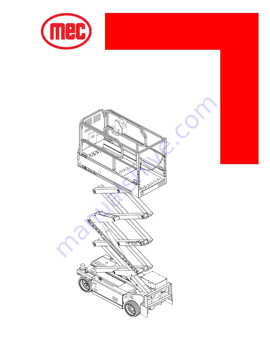
1532ES / 1932ES

Summary of Contents for 1532ES

Page 1: ...This Operator s Manual MUST BE READ AND UNDERSTOOD prior to operating your MEC Aerial Work Platform OPERATOR S MANUAL Part 90720 Rev A Issued May 2005 1532ES 1932ES ...

Page 2: ......

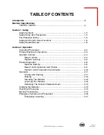
Page 3: ...edures 2 2 Primary Machine Components 2 3 Operator Controls 2 4 Base Controls 2 4 Platform Controls 2 6 Prestart Inspection 2 8 Machine Start Up 2 8 Base Control Operation And Checks 2 9 Platform Control Operation And Checks 2 10 Operation 2 11 Driving And Steering 2 11 Braking 2 12 Elevating The Platform 2 12 Lowering The Platform 2 12 Extending The Roll Out Extension Deck 2 13 Charging the Batte...

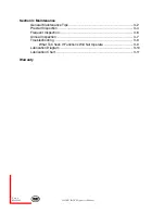
Page 4: ...al Section 3 Maintenance General Maintenance Tips 3 2 Prestart Inspection 3 4 Frequent Inspection 3 6 Annual Inspection 3 7 Troubleshooting 3 9 What To Check If Functions Will Not Operate 3 9 Lubrication Diagram 3 10 Lubrication Chart 3 11 Warranty ...

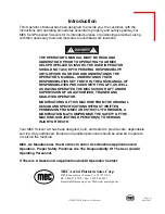
Page 5: ...L AS HAVING OPERATED THE MEC SCISSOR LIFT UNDER SUPERVISION OF AN AUTHORIZED TRAINED AND QUALIFIED OPERATOR MODIFICATIONS OF THIS MACHINE FROM THE ORIGINAL DESIGN AND SPECIFICATIONS WITHOUT WRITTEN PERMISSION FROM MEC ARE STRICTLY FORBIDDEN A MODIFICATION MAY COMPROMISE THE SAFETY OF THE MACHINE SUBJECTING OPERATOR S TO SERIOUS INJURY OR DEATH Your MEC Scissor Lift has been designed built and test...

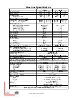
Page 6: ... 2 725 lbs 1236 kg 3060 lbs 1388 kg Drive System Proportional Drive Speed Platform Elevated 0 0 5 mph 0 0 8 km h Drive Speed Platform Lowered 0 2 5 mph 0 4 02 km h Lift Lower Speed Approx 17 sec 20 sec Gradeability 25 14 degrees Ground Pressure Wheel Maximum 105 psi 7 4 bar 113 psi 7 9 bar Wind Speed Maximum 0 mph 0 km h Tire Size Standard Solid non marking rubber 14 in dia x 4 5 in 35 56 cm x 11 ...

Page 7: ...Page 1 1 1532ES 1932ES Operator s Manual May 2005 SECTION 1 SAFETY ...

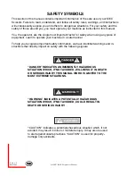
Page 8: ...uipment Learn to operate your machine in a safe manner To help you recognize important safety information we have identified warnings and in structions that directly impact on safety with the following signals DANGER INDICATES AN IMMINENTLY HAZARDOUS SITUATION WHICH IF NOT AVOIDED WILL RESULT IN DEATH OR SERIOUS INJURY THIS SIGNAL WORD IS LIMITED TO THE MOST EXTREME SITUATIONS WARNING INDICATES A ...

Page 9: ... Maintain safe clearance from electrically charged conductors power lines and apparatus You must allow for machine sway side to side movement when elevated and electrical line movement This machine does not provide protection from contact with or proximity to an electrically charged conductor You must maintain a CLEARANCE OF AT LEAST 10 FEET 3 05 m between any part of the machine or its load and a...

Page 10: ...against machine runaway on sloping surfaces Movement speed shall not exceed 5 MPH 8 0 kph NEVER attempt to open any hydraulic line or component without first relieving all system pressure NEVER alter modify or disable any safety devices or interlocks NEVER recharge the battery near sparks or open flames Lead acid batteries gener ate EXPLOSIVE HYDROGEN GAS Always wear safety glasses NEVER use the m...

Page 11: ...tute ANSI SIA A92 6 Standard It is prohibited to use an Aerial Work Platform manufactured by MEC with any portion or all of the guardrails removed Lanyard anchorage points on this type of equipment are not required to conform to the applicable ANSI SIA Standard THE IMPROPER USE OF FALL ARREST SYSTEMS MAY CAUSE MACHINE TO TIP RESULTING IN SERIOUS INJURY OR DEATH However if anchorage points for lany...

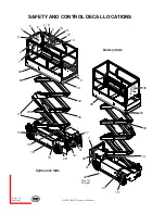
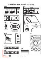
Page 12: ...532ES 1932ES Operator s Manual 6 1 22 29 2 3 4 23 24 20 18 15 28 32 25 5 7 8 9 10 11 12 13 2 14 33 16 31 22 7 26 21 19 27 15 29 33 30 34 17 Battery Side Hydraulics Side Front of Charger SAFETY AND CONTROL DECAL LOCATIONS ...

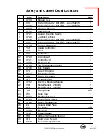
Page 13: ...nt 1 11 8391 Control Box 1 12 90723 Warning Light 1 13 90741 Control Box ID 1 14 90739 Made in USA 1 15 90725 Tire Replacement Warning 4 16 90748 Fork Pockets 1 17 8779 Battery Charging 1 18 90727 Emergency Down 1 19 9052 Battery Disconnect 1 20 6873 Hydraulic Fluid 2 21 90732 Electrical Moisture Warning 1 22 9138 Model Number 2033ES 2 8816 Model Number 2633ES 2 23 7982 Safety Stripe A R 24 8503 K...

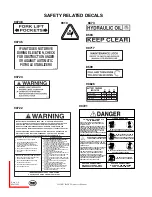
Page 14: ...E IS ON A TRUCK FORKLIFT OR OTHER DEVICE OR VEHICLE 11 DO NOT USE LADDER SCAFFOLDING OR OTHER DEVICES TO INCREASE SIZE OR WORKING HEIGHT OF PLATFORM 12 DO NOT ENTER OR EXIT PLATFORM WHILE IN MOTION 13 DO NOT RECHARGE BATTERIES NEAR SPARKS OR OPEN FLAME BATTERIES EMIT HIGHLY EXPLOSIVE HYDROGEN GAS 14 DO NOT PERFORM SERVICE ON THE MACHINE WITHOUT PROPERLY BLOCKING ELEVATING ASSEMBLY 15 DO NOT ATTACH...

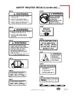
Page 15: ...ST BE PROPERLY CLOSED AND ALL GUARDRAILS PROPERLY IN PLACE AND SECURED BEFORE OPERATING FROM PLATFORM 90730 PLATFORM EXTENSION MUST BE LOCKED IN PLACE AT ALL TIMES SHEET LOADING GATE MUST BE IN LOWERED LOCKED POSITION BEFORE OPERATING FROM PLATFORM FAILURE TO FOLLOW INSTRUCTIONS COULD CAUSE DEATH OR PERSONAL INJURY MANUALS INSIDE 90733 DO NOT POWERWASH OR SPRAY ELECTRONIC COMPONENTS OR CONNECTORE ...

Page 16: ... EVENLY DISTRIBUTED EXTENSION RETRACTED EXTENSION EXTENDED SIDE LOAD 500 LBS 227 kg 250 LBS 113 kg 250 LBS 113 kg 100 LBS 444 N 2 PERSONS 1 PERSON 1 PERSON 9052 9137 9138 9137 MAXIMUM PLATFORM CAPACITY EVENLY DISTRIBUTED EXTENSION RETRACTED EXTENSION EXTENDED SIDE LOAD 600 LBS 272 kg 350 LBS 159 kg 250 LBS 113 kg 100 LBS 444 N 2 PERSONS 1 PERSON 1 PERSON 8402 ...

Page 17: ...Page 2 1 1532ES 1932ES Operator s Manual May 2005 SECTION 2 OPERATION ...

Page 18: ...FROM A TRUCK OR TRAILER IF DRIVEN OFF WE DO NOT RECOMMEND UNASSISTED LOADING OR UNLOADING OF ANY SCISSOR LIFT READ AND UNDERSTAND ALL SAFETY CONTROL AND OPERATING INFORMATION FOUND ON MACHINE AND IN THIS MANUAL BEFORE OPERATING THE MACHINE Attach the machine to a winch for the unloading Perform Machine Start up procedures in this section Refer to Operator Controls Descriptions as necessary Remove ...

Page 19: ...Page 2 3 1532ES 1932ES Operator s Manual May 2005 Control Box Platform Roll out Extension Deck Main Platform Deck Beams Base Control Panel Ladder Base Lift Cylinder PRIMARY MACHINE COMPONENTS ...

Page 20: ... 3 Base Off Platform Select BASE position to control operation of machine using Selector Switch the base controls Select PLATFORM position to control opera tion of machine using the platform console NOTE A key shall be provided for European machines and will be removable in PLATFORM position only 4 Battery Gauge Indicates percent of charge left in batteries Optional 5 Emergency Stop Use to stop al...

Page 21: ...HE SAFE OPERATION OF THIS MACHINE TRAINING INCLUDES COMPLETE KNOWLEDGE OF THE SAFETY AND OPERATION INSTRUCTIONS CONTAINED IN THE MANUFACTURERS MANUAL ANSI MANUAL OF RESPONSIBILITIES YOUR EMPLOYERS WORK RULES AND APPLICABLE GOVERNMENTAL REGULATIONS AN UNAUTHORIZED AND UNTRAINED OPERATOR SUBJECTS THEMSELF AND OTHERS TO DEATH OR SERIOUS INJURY MAINTAIN SAFE CLEARANCE FROM ELECTRICAL LINES AND APARATU...

Page 22: ...Page 2 6 May 2005 1532ES 1932ES Operator s Manual OPERATOR CONTROLS continued PLATFORM CONTROLS 90729 8391 1 5 3 2 4 1c 1a 1b 1d ...

Page 23: ...he left right to turn steer wheels to the right 1d Lift Lower With enable bar depressed moving controller handle Controller toward the operator up will provide platform lift at a speed propor tional to handle movement Moving the handle away from the operator down will provide platform lowering at a fixed speed 2 Tilt Warning Light Indicates that machine is not level 3 Torque On Off Switch ON selec...

Page 24: ...ll warning and instructional labels are legible and secure Check the platform guard rail system Insure platform entry properly closes and secures Ensure that emergency stop buttons on the base control panel and the platform controls are disengaged Reset by turning clockwise Ensure that the battery disconnect switch is in the ON position MACHINE START UP 1 Ensure the battery disconnect switch locat...

Page 25: ...ERATE THE MACHINE IF THE FOLLOWING CHECKS REVEAL A DEFECT Turn selector switch to BASE position Activate the Lift Lower switch on the base control panel to elevate the platform to the end of its movement Releasing the switch should stop elevation Test the Emergency Stop function While the platform is moving press the Emer gency Stop button platform should stop Reset by rotating clockwise Lower the...

Page 26: ...r platform depress the Enable bar and move control handle down away from the operator IF PLATFORM SHOULD FAIL TO LOWER DO NOT ATTEMPT TO CLIMB DOWN THE BEAM ASSEMBLY SERIOUS INJURY MAY RESULT IMPORTANT Always check front steer wheel direction before driving Move mode select switch to Drive position Test Left Right steering by depressing Enable bar on control handle and pressing the rocker switch a...

Page 27: ...LES AND DROP OFFS AND IS CAPABLE OF SUPPORTING THE MACHINE NOTE To activate drive function activate mode selector switch in Drive position Depressing the Enable bar drive and steer functions can be achieved Steer wheels will not center themselves after a turn and must be returned to the straight ahead position with the steer switch Controller handle movement away from the operator will give FORWAR...

Page 28: ...tform Rate of lift is proportional and is dependent on the movement of the controller handle USING BASE CONTROLS With selector switch in the Base position press and hold the Lift Lower toggle switch on the base control panel in the Up position until the desired height is reached or until the platform reaches maximum height LOWERING THE PLATFORM USING PLATFORM CONTROLS To lower the platform activat...

Page 29: ...nsion deck IF THE ROLL OUT DECK IS EXTENDED CHECK FOR CLEARANCE UNDER DECK AREA BEFORE LOWERING PLATFORM CHARGING THE BATTERIES LEAD ACID BATTERIES GENERATE EXPLOSIVE GASES KEEP SPARKS AND FLAME AWAY FROM BATTERIES NO SMOKING Plug the battery charger into 115 volt 60 Hz AC outlet using 12 AWG grounded extension cord to recharge the batteries To determine if the batteries are fully charged plug the...

Page 30: ... in Off position when leaving the machine at the end of the work day Put a padlock on the battery disconnect switch to prevent unauthorized operation MOVING THE MACHINE Machine can be winched or moved short distances in case of power failure at speeds not to exceed 5 MPH 8 05 kph TOWING WINCHING THE MACHINE Your machine is equipped with a brake release PRIOR TO MANUALLY RELEASING BRAKES INSURE WHE...

Page 31: ...RELEASING THE BRAKES THERE IS NOTHING TO STOP THE MACHINE S TRAVEL MACHINE WILL ROLL FREELY ON SLOPES BE ON GUARD AGAINST RUNAWAY DO NOT DRIVE MACHINE WITH BRAKES RELEASED To Reset Brakes Brakes will reset when drive function is activated or reset by pulling on manual brake release valve MOVING THE MACHINE continued ...

Page 32: ...D PROCEDURES IF THE CONTROL SYSTEM FAILS WHILE THE PLATFORM IS ELEVATED HAVE AN EXPERIENCED OPERATOR USE THE EMERGENCY LOWERING PROCEDURE TO SAFELY LOWER THE PLATFORM NEVER CLIMB DOWN BEAM ASSEMBLY WHEN PLATFORM IS RAISED BEFORE LOWERING PLATFORM RETRACT THE DECK EXTENSION ...

Page 33: ...platform perform the following steps 1 Pull and turn knurled knob on lift cylinder counterclockwise to lock the valve in open position 2 Pull manual activator override valve on main manifold to lower platform to desired height 3 To return to normal operation turn knurled knob on lift cylinder clockwise Valve will automatically lock 8599 Cylinder Valve Manual Activator 8599 ...

Page 34: ...Page 2 18 May 2005 1532ES 1932ES Operator s Manual ...

Page 35: ...Page 3 1 2033ES 2633ES Operator s Manual May 2005 SECTION 3 MAINTENANCE ...

Page 36: ... of mechanical failure and resulting downtime is reduced to a minimum NEVER PERFORM SERVICE ON THE MACHINE WITH THE PLATFORM ELEVATED WITHOUT FIRST BLOCKING THE BEAMS SCISSORS ASSEMBLY IN PLACE USING THE MAINTENANCE LOCK Block scissors assembly using maintenance lock if machine is in the elevated ex tended position Never leave hydraulic components or hoses open They must be protected from contamin...

Page 37: ...t recommended intervals may result in the unit being operated with a defect that could result in injury or death of the operator Immediately report to your supervisor any Defect or malfunction Any defect shall be repaired prior to continued use of the scissor lift Inspection and maintenance should be performed by qualified personnel familiar with the equipment Fluid leaks under pressure may not al...

Page 38: ... disconnected wires damaged tires etc Replace components as necessary ________ 2 Check the hydraulic fluid level with the platform fully lowered ________ 3 Check the tires for damage Check wheel lug nuts for tightness ________ 4 Check the hoses and the cables for worn areas or chafing Replace if necessary ________ 5 Check the platform rails and safety gate for damage ________ 6 Check the pivot pin...

Page 39: ...he base controls for proper operation Check all switches and push buttons for proper operation ________ 11 Check the platform controls for proper operation Check all switches and push buttons as well as ensuring that the drive controller returns to neutral DATE_______________________ INSPECTED BY_______________________ ...

Page 40: ...pervisor MODEL NUMBER____________ SERIAL NUMBER_________________ INITIAL DESCRIPTION ________ 1 Perform all checks listed on Prestart Inspection ________ 2 Inspect the condition of hydraulic fluid in the reservoir Oil should have a clear amber color ________ 3 Inspect the entire machine for signs of damage broken welds loose bolts improper or makeshift repairs ________ 4 Check the pin joints and r...

Page 41: ...S INJURY MODEL NUMBER____________ SERIAL NUMBER_________________ Owner User is responsible for Annual Inspections The inspection must be performed by a person s qualified as a me chanic on this specific make and model of aerial work platform Keep inspection records up to date Record and report all discrepancies to your supervisor ANNUAL INSPECTION TO BE PERFORMED IN ACCORDANCE WITH THE ANNUAL INSP...

Page 42: ... Operational Contactors Secure Pump Secure Batteries Secure Fully Charged Battery Charger Secure Operational Emergency Stop Breaks All Circuits Operation Wires Tight Switches Secure All Functions Operational Emergency Down Operational Slow Speed Limit Switch Set Properly Pothole Bars Operate Smoothly Lock In Place Limit Switches Adjusted Pressures Hydraulics Oil Filter Secure Chg Oil Level Correct...

Page 43: ...OR AND DO NOT USE THE MACHINE UNTIL IT HAS BEEN CHECKED BY A TRAINED QUALIFIED MECHANIC WHAT TO CHECK IF FUNCTIONS WILL NOT OPERATE Battery cutoff switch Is a function toggle switch or the enable switch not activated Is the Base Off Platform switch in the proper position Batteries fully charged Check emergency stop buttons at both base and platform Hydraulic fluid level low Obvious fluid leak or d...

Page 44: ...Page 3 10 May 2005 1532ES 1932ES Operator s Manual LUBRICATION DIAGRAM Hydraulic Lubrication 2 1 3 ...

Page 45: ...se FREQUENCY OF LUBRICATION Check Daily Analyze Every Six 6 Months Or 500 Hours Change Yearly Or Every 1 000 Hours Whichever Occurs First Change Every Six Months Or 500 Hours Whichever Occurs First For Normal Usage Change Every Three Months Or 300 Hours Which ever Occurs First For Severe Usage Weekly or Every 25 Hours Whichever Occurs First LUBRICATION CHART ITEM Hydraulic Reservoir Hydraulic Filt...

Page 46: ...Page 3 12 May 2005 1532ES 1932ES Operator s Manual ...

Page 47: ...d on MEC Aerial Platform Sales Corp s then current flat rate provided the defective part in question is shipped prepaid to MEC Aerial Platform Sales Corp and is found upon inspection by MEC Aerial Platform Sales Corp to be defective in material and or workmanship MEC Aerial Platform Sales Corp shall not be liable for any consequential incidental or contingent damages whatsoever Use of other than f...

Page 48: ...Aerial Platform Sales Corp 4780 E Jensen Ave Fresno CA 93725 USA Ph 1 866 379 7278 559 263 9626 Fax 559 263 9631 www mecawp com ...

Reviews: