background image

MD8000 Multimedia 

Transport System 

Operational Manual

For Release 8.21

MD8000 Rev. H

Summary of Contents for MD8000 Series

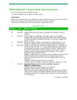
Page 1: ...MD8000 Multimedia Transport System Operational Manual For Release 8 21 MD8000 Rev H ...

Page 2: ......

Page 3: ...MD8000 Multimedia Transport System Operational Manual For Release 8 21 MD8000 Rev H ...

Page 4: ...changes Minor editorial changes E 12 21 2009 Chapter 2 Under Features added trunk boards 10GbE JP 1GbE 2Sch JP and 10G WAN JP to Table 2 1 changed 1GbE 2Sch board name to1GbE 2Trunk Added channel service boards STM 1 OC3 2Sch 1GbE 2Sch VIF 1Sch OPT and AIF 4Sch to Table 2 2 added Trunk to Trunk connection description section added Hitless Switching description section Delay Adjustment Buffer descr...

Page 5: ...Commands Added MAC Table Commands Added opposite parameter to CPU reset command Chapter 8 Web Operation Config Page Changed RD mode changes to RD mode setting Modified SD card spec H 3 20 2013 Contains revision changes 8 21 Chapter 1 Add MD8000SX Manual to Related Documentation Chapter 2 Added the SPU card MD8000SX chassis reference to the Introduction Updated Trunk to Trunk communications Chapter...

Page 6: ......

Page 7: ...nd Trunk to Trunk Communication Dual SWCNT 2 18 Supplemental Information 2 19 Packet flow from Trunk to SWCNT 2 19 Packet flow from SWCNT to Trunk 2 19 Inband Single SWCNT Use 2 19 Packet Loop 2 21 Hitless Switching 2 22 Hitless Switching With Dual SWCNT Boards 2 23 Hitless Switching with a Single SWCNT Board 2 25 Switching Mode Transition 2 26 Delay Adjustment Buffer 2 28 Dual SWCNT Operation 2 3...

Page 8: ... Cautions 3 6 2 Required Pre Installation Requirements 3 6 3 MD8000 Chassis Installation Procedures 3 6 3 Rack Mount Installation of the MD8000 Chassis 3 6 4 Removing Chassis Front Panel Cover 3 6 6 Installing the Chassis Power Supplies 3 6 7 Installing SWCNT 9 Switch Controller Front Boards 3 6 8 Installing Trunk or Channel Service Front Boards 3 6 10 Installing Rear Boards or Blank Panels in the...

Page 9: ... 3 9 3 DC Power Supply 3 9 3 SWCNT Specifications 3 9 4 Chapter 4 Other MD8000 Multimedia Transport Systems Chapter 5 MD8000 Series Troubleshooting Tips The Equipment Does Not Turn On 5 1 No Video Output 5 1 Chapter 6 Firmware Updates Logging into CLI using Telnet 6 1 SWCNT Firmware Update 6 3 Procedure 6 3 Troubleshooting Tips 6 4 Trunk and Channel Service Board FPGA Updates 6 5 Initial Setup 6 5...

Page 10: ...7 32 fwrite 7 32 Board Reconfiguration Command 7 34 reconfig 7 34 FPGA File Display Command 7 36 blkshow 7 36 Firmware Update Command 7 37 firmupdate 7 37 CPU Reset Command 7 39 reset 7 39 Display Current Firmware Version 7 39 ver 7 39 Help Command 7 40 help 7 40 Command History Command 7 40 history 7 40 System Logout Command 7 41 logout 7 41 MAC Table Commands 7 41 mac address table show 7 41 mac...

Page 11: ...is Log Messages 9 1 Service Log 9 1 Monitor Log 9 1 Network Log Messages 9 2 Service Log 9 2 SWCNT Log Messages 9 3 Service Log 9 3 Monitor Log 9 5 Appendix A Cleaning Fiber Optic connectors Fiber Optic Bulkhead Adapters A 1 Fiber Optic Cable Connectors A 1 Index ...

Page 12: ...vi MD8000 Transport System MD8000 Rev H This Page Intentionally Left Blank ...

Page 13: ...fety Information This section contains the safety precaution symbols used in this manual that are necessary for protecting users and third parties and preventing damage to the product Please adhere to these Caution and Warning messages at all times Terminology In this manual SWCNT 9X1 refers to the original switch controller card SWCNT 9X2 refers to the new switch controller card new Ethernet swit...

Page 14: ...tention to a particular part of a procedure that is considered important This symbol provides additional information and tips that might aid the user in performing indicated tasks Laser Safety This equipment uses a semiconductor laser system that is a class 1 laser product that is FDA acceptable complies with 21CFR 1040 10 and 1040 11 This class 1 laser product is also IEC 60825 acceptable Do not ...

Page 15: ...s or modules without permission from Media Links could cause physical harm and or equipment damage Opening will void the equipment module warranty Allowable on site repairs are indicated in this manual Return all other equipment modules to Media Links for repair Do not insert any foreign objects into the equipment Such an occurrence may cause a fire or electrical shock Do not place any heavy equip...

Page 16: ...equipment is to be powered provides a connection to the building protective earth lf not the SERVICE PERSON shall arrange for the installation of a PROTECTIVE EARTHING CONDUCTOR from the separate protective earthing terminal to the protective earth wire in the building This product utilizes two 2 AC line cords Disconnect all cords before servicing FCC WARNING Changes or modifications not expressly...

Page 17: ...l and fans located on the rear panel to prevent internal overheating Blocking the air circulation vent or fans will cause overheating which may result in an equipment failure or a fire Avoid any direct contact with the fans while the system is in operation Use two people to handle the equipment The equipment weighs about 100 lbs 45kg when fully loaded To avoid injury the equipment should be handle...

Page 18: ...a residential area is likely to cause harmful interference in which case the user will be required to correct the interference at his own expense Canada This Class A digital apparatus meets all requirements of the Canadian Interference Causing Equipment Regulations Cet appareil num erique de la classe A respecte toutes les exigences du R eglement sur le mat eriel brouilleur du Canada EU This is a ...

Page 19: ...nd or specifications by checking with Media Links support personnel see contact information below Related Documentation Contact Information If any signs of an equipment or software failure are observed please contact Media Links Technical Support Media Links Inc 1294 Blue Hills Ave Bloomfield CT 06002 Toll Free North America 1 866 801 5397 Phone 1 860 206 9163 Fax 1 860 206 9165 Web www medialinks...

Page 20: ...1 8 MD8000 Multimedia Transport System MD8000 Rev H This Page Intentionally Left Blank ...

Page 21: ...port System Hereinafter referred to as MD8000 Series system encapsulates the HD SDI SD SDI DVB ASI signals AES audio signals E1 T1 circuit signals and or 10 100Base Ethernet signals into IP frames to transport over SDH SONET and or 10Gbit 1Gbit Ethernet networks The MD8000 Series system has the following four 4 types of boards SWCNT boards to switch the IP packets Trunk boards to interface with th...

Page 22: ...ion page 1 7 The MD8000 is a 4U chassis device with up to two 2 SWCNT 9 boards for packet switching between up to nine 9 Trunk boards and Channel Service boards installed in the chassis There is both an AC or DC version available Details are contained in this manual The MD8000EX is a 7U chassis device with up to two 2 SWCNT 24 boards for packet switching between up to twenty four 24 Trunk boards a...

Page 23: ...m the network Note that the main difference between these two interface categories is that Signal interfaces perform encapsulation de encapsulation whereas Trunk interfaces do not Existing and planned Trunk interface types include Table 2 1 Trunk Boards Name Description 1GbE 2Trunk 1Gbps 2 port Transmit Receive 1GbE 2Trunk JP 1Gbps 2 port Transmit Receive Jumbo frame support 10GbE 1Trunk 10Gbps Tr...

Page 24: ...S Audio Transmit Receive AIF 4Sch Uncompressed AES Audio Transmit Receive E1 T1 4Sch 2 048Mbps E1 or 1 544Mbps T1 circuit signals 4 Channels E1 T1 8Sch 2 048Mbps E1 or 1 544Mbps T1 circuit signals 8 Channels FE 4Sch 10 100Mbps 4 port Transmit Receive J2K 1Sch 2022 JPEG2000 method Video compression Encoder or Decoder IP Frame transportation based on SMPTE 2022 J2K 1Sch 2022VBR JPEG2000 method Video...

Page 25: ...ems can be monitored and controlled from a remote client PC through In band communication sharing the transport network without using the dedicated circuit UVRX 4Sch SDI 2022 Output up to four signals received through SWCNT boards Signal outputs are reproduced from uncompressed video IP packets VIF 1Sch Uncompressed HD SD SDI DVB ASI Transmit Receive VIF 1SC OPT Uncompressed HD SD SDI DVB ASI Tran...

Page 26: ...ement All MD8000 board assemblies consist of a front application board and a separate rear board for fiber cable connections The MD8000 front application boards can be replaced without detaching the connected cables preventing possible errors that may occur while disconnecting and reconnecting cables The MD8000 boards power supplies and cooling fans are Hot swappable as they can be replaced while ...

Page 27: ...configuration with various types of trunk boards and channel service boards System monitoring can be conducted from a supervisory terminal PC A supervisory terminal can provide access to the Web server on a SWCNT board to configure monitor the trunk boards and channel boards Figure 2 1 MD8000 Configuration Example ...

Page 28: ... an MD8000EX shelf at the network hub to provide switching multicasting and grooming capabilities On the right native IP networks are used to leverage the low cost and extreme flexibility of this rapidly growing technology Notice particularly the central hub of the IP network each individual MD8000 signal stream is uniquely identified to the IP core network to allow grooming switching and multicas...

Page 29: ...backbone All of the switching elements located in each shelf are completely non blocking and support any conceivable type of 1 to N multipoint distribution Signals can be looped back within any chassis and connected to any combination of other interfaces Figure 2 3 Chassis Block Diagram Network Management The following software applications are available for either local or remote board configurat...

Page 30: ...Operation To Support Hitless Switching In the originating System 1 the Channel Service board duplicates the encapsulated video signal with the different MAC addresses M1 1 and M1 2 and feeds them to a SWCNT board The SWCNT board switches the M1 1 packets to the Line 1 Trunk board and M1 2 packets to Line 2 Trunk board The Trunk boards transmit the supplied packets to the network In the receiving S...

Page 31: ...m to each corresponding SWCNT board in CPU ACT or STB state See Dual SWCNT Operation page 2 33 for Dual SWCNT operation Each SWCNT board passes them to the corresponding Trunk board The Trunk boards transmit the supplied packets to the network In the receiving System 2 two Trunk boards transfer the received packets to the corresponding SWCNT boards ACT or STB which pass the received packets to the...

Page 32: ...s packets to the Line 2 input of the same Trunk board The Trunk board transmits out to the network packets arrived through the ACT SWCNT board and discards all the packets from the STB SWCNT board The Trunk board continuously monitors the ACT input packet flow and if it drops off for a certain period of time the board automatically switches to use the packets from the STB stream In the receiving S...

Page 33: ...WCNT board The Trunk board continuously monitors the ACT input packet flow and if it drops off for a certain period of time the board automatically switches to use the packets from the STB stream In the receiving System 2 both Trunk boards duplicate the received packets and deliver the same to both 1 ACT and 2 STB SWCNT boards The 1 SWCNT board passes all the received packets to the Line 1 input o...

Page 34: ...anID1 1000 10gEther 1 10gEther 2 Tx VlanID2 2000 Mac 01 10 C4 00 01 00 01 10 C4 00 01 01 Dst Mac1 01 10 C4 00 01 00 Rate 1 1 Dst Mac2 01 10 C4 00 01 01 VlanID 1000 2000 Comment Field Trunk Type 0 0 Chassis B VIF 3 Rx Setting 10gEther 5 Trunk to Trunk Setting Rx VlanID1 1000 10gEther 3 10gEther 4 Rx VlanID2 2000 Mac 01 10 C4 00 01 00 01 10 C4 00 01 01 Rx Mac1 01 10 C4 00 01 00 Rate 1 1 Rx Mac2 01 1...

Page 35: ...Index 1 Slot 12 Index 2 Slot 24 Port1InbandCommunication 1 0 Chassis B InbandVlanIdSetting 1000 10gEther Inband Setting Index 1 Slot 12 Index 2 Slot 24 Index 1 Slot 13 Port1InbandCommunication 1 0 1 Chassis C InbandVlanIdSetting 1000 10gEther Inband Setting Index 1 Slot12 Index 2 Slot24 Index 1 Slot13 Port1InbandCommunication 1 0 0 SWCNT 1 Slot 26 VIF 1 Slot 1 10gEther 1 Slot 12 10gEther 2 Slot 24...

Page 36: ...Table 2 6 Parameter Single SWCNT Setting Example 2 Chassis A InbandVlanIdSetting 1000 10gEther Inband Setting Index 1 Slot 12 Index 2 Slot 24 Port1InbandCommunication 1 0 Chassis B InbandVlanIdSetting 1000 10gEther Inband Setting Index 1 Slot 12 Index 2 Slot 24 Index 1 Slot 13 Port1InbandCommunication 1 0 1 Chassis C InbandVlanIdSetting 1000 10gEther Inband Setting Index 1 Slot 12 Index 2 Slot 24 ...

Page 37: ...et Loop Example 2 Table 2 7 Parameter Setting Single SWCNT Example 2 Chassis A InbandVlanIdSetting 1000 10gEther Inband Setting Index 1 Slot 12 Index 2 Slot 24 Port1InbandCommunication 1 0 Port2InbandCommunication 0 0 Chassis B InbandVlanIdSetting 1000 10gEther Inband Setting Index 1 Slot 12 Index 2 Slot 24 Port1InbandCommunication 1 1 Port2InbandCommunication 0 0 Chassis C InbandVlanIdSetting 100...

Page 38: ... 2 Slot 24 Port1InbandCommunication 1 0 Chassis B InbandVlanIdSetting 1000 10gEther Inband Setting Index 1 Slot 12 Index 2 Slot 24 Index 1 Slot 13 Port1InbandCommunication 1 0 1 Chassis C InbandVlanIdSetting 1000 10gEther Inband Setting Index 1 Slot12 Index 2 Slot24 Index 1 Slot13 Port1InbandCommunication 1 0 0 SW CNT 1 Slot26 VIF 1 Slot1 10gEther 1 Slot12 10gEther 2 Slot24 VIF 2 Slot2 10gEther 3 ...

Page 39: ... CPUs Figure 2 13 Packet flow from Trunk to SWCNT Packet flow from SWCNT to Trunk In this case the 10bEther 1 Trunk board does not route the CPU 1 originated packets to the SWCNT 4 Figure 2 14 Packet flow from SWCNT to Trunk Inband Single SWCNT Use Figure 2 15 Inband Single SWCNT Use SW CNT 1 Slot26 VIF 1 Slot1 10gEther 1 Slot12 10gEther 2 Slot24 VIF 2 Slot2 CPU 1 SW CNT 4 Slot25 CPU 4 SW CNT 1 Sl...

Page 40: ... and firmware support the extended capability Other boards or older version of hardware or firmware do not support this single SWCNT use Table 2 9 Required Versions of Hardware and Firmware Board Hardware Firmware 10GbE 1Trunk or 10GbE 1Trunk JP MD8K_10GbE_0800_v04xx or later Version 5 06 or later 10GWAN 1Trunk or 10GWAN 1Trunk JP MD8K_10GWAN_0800_v04xx or later Version 5 06 or later 1GbE 2Trunk J...

Page 41: ...ommunication 1 0 Chassis B InbandVlanIdSetting 1000 10gEther Inband Setting Index 1 Slot 12 Index 2 Slot 24 Index 1 Slot 13 Port1InbandCommunication 1 0 1 Chassis C InbandVlanIdSetting 1000 10gEther Inband Setting Index 1 Slot 12 Index 2 Slot 24 Index 1 Slot 13 Port1InbandCommunication 1 1 0 SW CNT 1 Slot26 VIF 1 Slot1 10gEther 1 Slot12 10gEther 2 Slot24 VIF 2 Slot2 10gEther 3 Slot12 10gEther 4 Sl...

Page 42: ...INE 1 to LINE 2 Hitless Switching SEL 1 2 Error Detection 1 2 1 2 1 2 EAST WEST Timing Buffer ED Buffer ED Buffer Error Dection Buffer ED Buffer Network VTX Encoder Trunk Board LINE1 TX LINE2 TX Trunk Board MD8000 L1 P 11 L1 P 10 Trunk Board LINE1 RX LINE2 RX Trunk Board L1 P 8 L1 P 7 L1 P 11 L1 P 10 L1 P 8 L1 P 7 MD8000 L1 P 5 L1 P 6 L1 P 5 L1 P 6 VRX FIFO 1 FIFO 2 Decoder L1 P 2 L1 P 3 L1 P 4 L1...

Page 43: ...s Switching Dual SWCNT Board Operation Figure 2 21 illustrates a little further in detail the behavior of the Channel Service boards Under the dual SWCNT board configuration as shown in Figure 2 21 two identical Stream packet streams except their destination address can be routed through the completely independent circuits between the peer Channel Service boards Figure 2 21 Operation Of Channel Se...

Page 44: ...2 24 MD8000 Multimedia Transport System MD8000 Rev H Figure 2 22 illustrates the transport process in the Dual SWCNT mode Figure 2 22 Transfer Process in the Dual SWCNT Mode ...

Page 45: ...l Service board and the SWCNT board Under the single SWCNT board configuration as shown in Figure 2 24 two identical Stream packet streams except their destination address can be routed through the completely independent circuits between peer SWCNT boards In this mode of operation two identical Stream packet streams except their destination address are transferred in one physical circuit between t...

Page 46: ...rt System MD8000 Rev H Switching Mode Transition Figure 2 25 successful switching and 2 26 unsuccessful switching show the sequences of Hitless switching events and states Figure 2 25 Successful Transition to Hitless Switching Mode ...

Page 47: ...MD8000 Rev H MD8000 Series Transport System Summary 2 27 Figure 2 26 Unsuccessful Transition to Hitless Switching Mode ...

Page 48: ...ronized for Hitless switching The MD8000 will automatically synchronize the shorter route packets to the longer route when the receiving function is enabled Users are allowed to change the default Loading Base point within the range between the Min and Max frames However in order to absorb the network fluctuation and jitter the Loading Base point should have some margin above underflow 12 for the ...

Page 49: ... 268 8Mbps 32 768 32 128 31 000 12 32 640 FEC OFF 249 6Mbps FEC ON 200 252 4Mbps 32 768 32 128 31 000 12 32 640 FEC OFF 234 3Mbps FEC ON 180 227 1Mbps 32 768 32 128 31 000 12 32 640 FEC OFF 210 9Mbps FEC ON 160 201 9Mbps 32 768 32 128 31 000 12 32 640 FEC OFF 187 5Mbps FEC ON 140 176 7Mbps 32 768 32 128 31 000 12 32 640 FEC OFF 164 0Mbps FEC ON 120 151 4Mbps 32 768 32 128 31 000 12 32 640 FEC OFF ...

Page 50: ...4 16 382 FEC OFF 12 3Mbps FEC ON 20 26 4Mbps 16 384 10 128 15 000 4 16 382 FEC OFF 24 6Mbps FEC ON 30 39 6Mbps 16 384 10 128 15 000 4 16 382 FEC OFF 36 9Mbps FEC ON 40 52 8Mbps 16 384 10 128 15 000 4 16 382 FEC OFF 49 2Mbps FEC ON 50 66Mbps 16 384 10 128 15 000 4 16 382 FEC OFF 61 5Mbps FEC ON 75 99Mbps 16 384 10 128 15 000 4 16 382 FEC OFF 99 2Mbps FEC ON 100 132Mbps 16 384 10 128 15 000 4 16 382...

Page 51: ... 331 0 902 2 455 FEC ON 120 6 802 2 669 2 607 10 428 2 525 0 948 2 659 FEC OFF 395 2 875 2 807 11 230 2 720 1 053 2 864 FEC ON 100 8 163 3 203 3 128 12 513 3 031 1 173 3 191 FEC OFF 474 3 450 3 369 13 476 3 264 1 263 3 436 FEC ON 90 9 070 3 559 3 476 13 904 3 367 1 303 3 545 FEC OFF 526 3 833 3 743 14 973 3 626 1 404 3 818 FEC ON 80 10 204 4 004 3 910 15 642 3 788 1 466 3 989 FEC OFF 592 4 312 4 2...

Page 52: ...19 16 435 10 031 129 397 15 047 4 012 16 433 FEC ON 20 39 822 7 658 4 674 59 827 7 011 1 870 7 657 FEC OFF 3 110 8 217 5 016 64 198 7 523 2 006 8 216 FEC ON 30 26 548 5 105 3 116 39 885 4 674 1 246 5 105 FEC OFF 2 073 5 478 3 344 42 799 5 016 1 337 5 478 FEC ON 40 19 911 3 829 2 337 30 914 3 506 0 935 3 828 FEC OFF 1 555 4 109 2 508 32 099 3 762 1 003 4 108 FEC ON 50 15 929 3 063 1 870 23 931 2 80...

Page 53: ...nd controlling the Channel Service boards O X Monitoring and controlling the Trunk boards O X Transmitting information to the other SWCNT board O X Receiving information from the other SWCNT board X O Setting the L2SW table in its own SWCNT board O X Setting the L2SW table in the other SWCNT board O X L2SW Part Dynamic routing of Data packets O X Static routing of Stream packets O O MD8000 SWCNT A...

Page 54: ...ame condition Only when SWCNT 1 has the wrong Chassis ID and 2 has the correct chassis ID the SWCNT 1 will be activated as Stand by with SWCNT 2 Active When a SWCNT board is Hot swapped the newly installed board will be activated as Stand by unless the other board is malfunctioning Figure 2 30 MD8000 SWCNT Boards POWE R MAINTE ERR FA N4 P OWE R MAINT E E RR FA N4 R R14 R 13 Front View Rear View SW...

Page 55: ...d effect relationship between ACT STB switching State Transition Figure 2 31 and 2 32 show the state transition diagrams of SWCNT 1 and 2 Figure 2 31 SWCNT 1 State Transition Table 2 14 Cause Effect of ACT STB Switching Item Cause Effect 1 Restart by WDT The ACT transitions to Down state and terminates the ACT state autonomously 2 L2SW Abnormal Same as above 3 SWCNT Hardware Failure Unpredictable ...

Page 56: ...2 36 MD8000 Multimedia Transport System MD8000 Rev H Figure 2 32 SWCNT 2 State Transition ...

Page 57: ... partly discarded in order to secure the necessary bandwidth for the Stream1 and 2 Stream frames Figure 2 33 Bandwidth Control Source Video MAC Address A unique 48 bit Video MAC address is automatically assigned to each source port of the MD8000 Channel Service boards as shown below Users cannot change the Source Video MAC address Stream2 Stream1 Data 10Gbps Data packets discarded t Data packets d...

Page 58: ...ing This processing can help provide advance warning of an imminent failure Network Log Messages Refer to Chapter 9 Log Messages page 9 1 Table 2 15 Monitoring for Advance Warnings Item Monitoring Point Standard Warning Criteria Power Board Power Supply 3 3V Out of 4 Range 1 8V Out of 4 Range 1 2V Out of 4 Range Temperature Board at Air Intake 40 C 1 C Board at Air Exhaust 55 C 1 C ...

Page 59: ... in this Chapter Section 3 1 MD8000 Chassis Description page 3 1 1 Section 3 2 MD8000 Power Supply Module page 3 2 1 Section 3 3 MD8000 SWCNT 9 Controller Module page 3 3 1 Section 3 4 MD8000 CN Alarm Module page 3 4 1 Section 3 5 MD8000 Chassis Fans page 3 5 1 Section 3 6 MD8000 Installation Procedures page 3 6 1 Section 3 7 MD8000 Network Management page 3 7 1 Section 3 8 MD8000 Maintenance Proc...

Page 60: ...3 2 MD8000 Multimedia Transport System MD8000 Rev H This Page Intentionally Left Blank ...

Page 61: ...ed on EIA or JIS standard The MD8000 Chassis has twelve 12 I O interface slots 9 single width or 6 single width and 3 dual width two 2 slot for a switch controller boards There are two 2 versions either AC or DC powered and can accept 1 or 2 redundancy power supplies Figure 3 1 1 MD8000 Chassis w Front Cover Installed Front View Figure 3 1 2 shows a front view of the MD8000 chassis front cover Fig...

Page 62: ...gure 3 3 1 on page 3 3 2 for MD8000 slot bandwidth allocation for communications with the SWCNT 9 board Slot J12 is the preferred slot for a Trunk card POWER MAINTE ERR FAN1 POWER MAINTE ERR FAN2 POWER MAINTE ERR FAN3 POWER MAINTE ERR FAN4 J1 Front Panel Hinges 2 Front Panel Clips 2 Front Panel Retainer Bracket 2 J12 J13 J14 PS1 PS2 FAN 1 to FAN 4 SWCNT 9 Front Boards Trunk Front Board Channel Ser...

Page 63: ...he same chassis PS1 PS2 PS Slots Slots for the MD8000 Power Supplies n AC Power Supplies require AC Chassis n DC Power Supplies require DC Chassis FAN1 FAN4 Front Fan Slots These slots are for the Front Fan Modules Hinges Two 2 hinges left and right side of chassis are used to support the Front Panel Clips Two 2 spring loaded clips left and right side of chassis are used to hold the Front Panel to...

Page 64: ... normally used for a single SWCNT 9 installation R15 CN Slot This slot is for the CN Alarm Module FAN1R 5R Rear Fan Modules Slots for five 5 MD8000 Rear Fan Modules AC1 AC2 AC Receptacles Receptacle for AC Power Supply PS1 and PS2 power cords Requires AC Power Supplies ALM 1PPS POWER MAINTE ERR POW ER MAINTE ERR POWER MAINTE ERR POWER MAINTE ERR POW ER MAINTE ERR FAN1R FAN2R FAN3R FAN4R FAN5R R14 ...

Page 65: ...d its associated hardware DC1 DC2 DC Terminal Blocks Terminals for DC Power Supply PS1 and PS2 power cables Requires DC Power Supplies FG Terminal Frame Ground terminal Table 3 1 3 MD8000 Chassis Part Numbers Part Number Description 4RU Chassis MD8000 4U 100V to 240V 50 Hz 60 Hz AC powered chassis MD8000 DC 4U 48VDC powered chassis MD8000BLANK Rear Blank Panels Table 3 1 2 MD8000 Rear Chassis Comp...

Page 66: ...3 1 6 MD8000 Multimedia Transport System MD8000 Rev H This Page Intentionally Left Blank ...

Page 67: ...scription page 3 2 2 DC Power Supply Physical Description page 3 2 3 Part Numbers page 3 2 3 Summary Either one or two power supply modules can be placed in an MD8000 chassis Installing two 2 power supplies will provide for a redundant power configuration n Two power supply modules utilizing the same input power source will provide power supply redundancy n Two power supply modules utilizing separ...

Page 68: ...ower supply unit in a dual operation mode can be replaced after turning off the breaker on the power supply front panel while the power is applied to the chassis Table 3 2 1 MD8000PS AC Power Supply Front Panel LEDs and Component Description Power Supply Module Label Component Color Description rocker switch Power ON OFF switch n On I n Off O POWER LED Green ON when power supply is turned ON and a...

Page 69: ...s applied to the chassis Table 3 2 2 MD8000PS DC Power Supply Front Panel LEDs and Component Description Power Supply Module Part Number Description MD8000PS AC Power Supply Module 100V to 240V 50Hz 60Hz input 500W 6 5A Max MD8000PS DC DC Power Supply Module 48VDC input 500W 13A Max POWER MEDIA LINKS MD 4U500 PS DC ALM 12V GND Label Component Color Description rocker switches Power ON OFF switchNo...

Page 70: ...3 2 4 MD8000 Multimedia Transport System MD8000 Rev H This Page Intentionally Left Blank ...

Page 71: ...e SWCNT board switches the mixed flows of MD8000 Stream frames and Data frames simultaneously In order to obtain a highly reliable system operation two SWCNT boards can be installed in a chassis in a 1 1 redundant configuration One SWCNT serves as the Active unit and the other the Standby unit See Dual SWCNT Operation page 2 33 for additional details on the dual SWCNT operation The SWCNT board is ...

Page 72: ...rds n Slots 2 4 and 6 are marked with an N designating that they have no communication with the SWCNT 9 boards These slots may be used when installing double wide modules n Slots 11 and 12 are marked with a C designating they are capable of extracting clock from an external network Figure 3 3 1 Bandwidth Allocation SWCNT 9 The new SWCNT 9X2 is equipped with a new L2SW but the functionality is basi...

Page 73: ...sh Memory SDC SD Card Controller LANC 10 100BASE TX Ethernet Controller E1 T1 Framer External clock extraction PT 10 100BASE TX Pulse Trance E1 T1 Pulse Trance Sync CLK CLT Division External clock synchronization control and delivery to Channel boards L2SW AXEL X Layer 2 Switch 1G PHY 1G Serial connection to the other SWCNT for HA High Availability communication path between AXEL Xs and between Po...

Page 74: ... components Table 3 3 1 SWCNT 9 Board Layout and Component Descriptions Silkscreen Component Description SW500 Switch Factory Use Only Caution Do not change these switch positions refer to Chapter 3 8 Re Initializing the SWCNT 9 Controller 1 OFF Must be kept turned off 2 ON Initialize IP addresses refer to page 3 8 10 for details 3 ON Initialize other parameters refer to page 3 8 10 for details 4 ...

Page 75: ...Amber TEMP Board Temperature High Advance Warning Board Air Intake 40o C 1o C Board Air Exhaust 55o C 1o C CPU WDTE LED Left Green CPU Board Active OFF when Standby LED Right Red WDTE Watchdog Timer Error Ex CLK BBS LED Left Green Ex CLK When connected to an external clocking source LED Right Green BB Black Burst Signal Input E W CLK LED Left Green E CLK When the shelf is synchronized to the activ...

Page 76: ...Connectors Front Panel Label Component Description Ex CLK D Sub 9 pin E1 T1 signal input for synchronization See Table 3 3 4 for connector pinout ETHER RJ 45 10 100BASE T Ethernet Interface n Use a cross cable for the direct PC connection n Use a straight cable for connection through a hub See Table 3 3 4 for connector pinout BB BNC 75ohm BBS Sync Input SNO VER MADE IN JAPAN MEDIA LINKS R MD8000 S...

Page 77: ...t Pin Assignment Ex CLK RJ 45 Table 3 3 5 SWCNT 9 Board Part Numbers Part Number Description 4RU Chassis MD8000 SWCNT 9 F 180 Gbit Switch and Controller Switch board to control up to 9 slots for MD8000 SWCNT 9 R 180 Gbit Switch and Controller Rear Board CDAA1504330 04 Rear Blank Panels Ex CLK 1 5 6 9 D Sub 9pin Pin No Signal Name 1 2 RXD 3 4 5 GND 6 RXD 7 8 9 RJ 45 8 Pole Modular Jack 8 7 6 5 4 3 ...

Page 78: ...3 3 8 MD8000 Multimedia Transport System MD8000 Rev H This Page Intentionally Left Blank ...

Page 79: ... and MD8000EX chassis Physical Description Table 3 4 1 shows a layout of the alarm panel and a description of the panel components Table 3 4 2 provides a pinout of the alarm connector Table 3 4 1 MD8000 MD8000EXPS Alarm Panel Component Description ALM Module ALM 1PPS ALM 1PPS POWER MAINTE ERR POWER MAINTE ERR POWER MAINTE ERR POWER MAINTE ERR POWER MAINTE ERR FA FAN2R FAN3R FAN4R FAN5R R14 R13 R12...

Page 80: ...Voltage Fan Failure Excess Current Voltage Abnormal Temperature OPEN Normal CLOSED Abnormal Relay Contact 30V DC max 1A 2 15 PS2 Failure PS2 Low Voltage Fan Failure Excess Current Voltage Abnormal Temperature 3 16 Chassis Fan Failure Failure of one or more of the Front Fan Units 1 4 or Rear Fan Units 1 3 4 17 Board Failure 1 Failure of one or more of boards in slot 1 12 5 18 Board Failure 2 MD8000...

Page 81: ... when operating with the corresponding speed the fans do not reduce the rotation speed until the temperature reaches down to this level Front Fan Modules The MD8000 has four 4 Hot Swappable front fan modules Each module contains two 2 fans These fans are use to draw cool air into the chassis Table 3 5 1 Cooling Fan Rotational Stages Measurement Temperature Rotation Hysteresis TempNote Fan unit Int...

Page 82: ...a description of the front panel LEDs Figure 3 5 1 Front View of Front Fan Module Table 3 5 2 MD8000 Front Fan LEDs Label Type Color Description POWER LED Green Fan power is normal MAINTE LED Amber Fan operating hours has exceeded 40 000 hours and requires replacement ERR LED Red Fan Failure Detected POWER MAINTE ERR ...

Page 83: ...LEDs Figure 3 5 2 Front View of MD8000 Rear Fan Module Part Numbers CAUTION Ensure the chassis exhaust vents are not blocked Restriction of exhaust air will eventually cause over heating of the chassis and potential damage chassis equipment installed or cause a fire Table 3 5 3 MD8000 Rear Fan LEDs Label Type Color Description POWER LED Green Fan power is normal MAINTE LED Amber Under Maintenance ...

Page 84: ...3 5 4 MD8000 Multimedia Transport System MD8000 Rev H This Page Intentionally Left Blank ...

Page 85: ...Front Boards page 3 6 10 Installing Rear Boards or Blank Panels in the MD8000 Chassis page 3 6 12 Connecting the MD8000 Chassis Power Cord page 3 6 13 Connecting I O Cables page 3 6 17 Turning on Chassis Power Supplies page 3 6 22 Reinstalling Chassis Front Panel Cover page 3 6 23 Installation Warning Caution Notes All installation Warning and Caution notes must be read prior to starting installat...

Page 86: ...ay result in an equipment failure or a fire Avoid any direct contact with the fans while the system is in operation CAUTION Avoid any direct contact with the fans while the system is in operation CAUTION The equipment weighs approximately 88 pounds 40kg fully loaded This equipment requires that it be carried and or installed by two personnel Doing otherwise may result in bodily injury Unless other...

Page 87: ...or installation of a new chassis in a 19 inch rack or cabinet It is important that the following Warning Notes are read prior to installation This equipment generates uses and can radiate radio frequency energy which may cause interference to radio communications Operation of this equipment in a residential area may cause interference to TV and radio reception in which case the user at his own exp...

Page 88: ...abinet Figure 3 6 1 Installing MD8000 Chassis into a Rack Cabinet Requires installation by two people The weight of this equipment is about 88 pounds 40 Kg when fully loaded Seek assistance when lifting or carrying the equipment Doing otherwise may result in bodily injury The equipment has an air circulation vent intake fans located on the lower part of the front panel and exhaust fans located on ...

Page 89: ...h lock washer on each of four binding head thread forming 1 2 inch by 12 24 or 10 32 mounting screws as applicable Align the four mounting holes in the front panel with the applicable holes in the rack and insert the four prepared mounting screws 4 Tighten the four mounting screws securely ...

Page 90: ...l cover 1 On the chassis front panel release the right and left spring loaded captive screws refer to Figure 3 6 2 2 Gripping the bottom of both sides of the panel pull the panel out until you feel the cover disengage from the chassis spring loaded clips 3 Then lift the cover up until the panel is free of the chassis hinges 4 Then out away from the chassis Figure 3 6 2 Removing Chassis Front Panel...

Page 91: ...e screw clockwise to secure the power supply to the chassis 5 For power supply redundancy repeat Steps 2 through 4 inserting the second redundant Power Supply into slot PS2 CAUTION The AC power supply unit only fits in the AC powered chassis and does not fit the DC powered chassis CAUTION The DC power supply unit only fits in the DC powered chassis and does not fit the AC powered chassis Do not fo...

Page 92: ...locked position 6 For a redundant SWCNT 9 Standby board repeat Steps 2 thru 5 placing the second SWCNT 9 in Slot 13 CAUTION Wear an ESD wrist strap in order to prevent ESD damage to the equipment CAUTION Take care when installing boards while power is applied to ensure the board does not come in contact with other boards within the chassis Ensure that the board is in both the upper and lower card ...

Page 93: ...that the SWCNT 9 board LEDs indicate normal operation Refer to Section 3 3 Table 3 3 2 SWCNT 9 Front Panel LED Indicators page 3 3 5 for LED descriptions CAUTION If the board LEDs indicate an abnormal condition note LED light patterns remove the card and notify Media Links Technical Support for guidance Operating when the LEDs on the display panel are in an abnormal state can cause damage to the c...

Page 94: ...ssis backplane connector Figure 3 6 5 Figure 3 6 5 Installing User Interface Front Boards 5 Secure the board by placing the board ejector handle to the up locked position CAUTION Wear an ESD wrist strap in order to prevent ESD damage to the equipment CAUTION Take care when installing boards while the power is applied to ensure the board does not come in contact with other boards within the chassis...

Page 95: ...rear boards refer to Installing Rear Boards or Blank Panels in the MD8000 Chassis page 3 6 12 8 With power applied confirm that the user interface board LEDs indicate normal operation CAUTION If the board LEDs indicate an abnormal condition note LED light patterns remove the card and notify Media Links Technical Support for guidance Operating when the LEDs on the display panel are in an abnormal s...

Page 96: ...ning empty slots must have a Blank Rear Panel installed To install the Blank Panels a Align Blank Panel Rear spring loaded captive screws with the top and bottom threaded slot holes on the chassis rails b Secure the Blank Panel to the chassis using rear panel spring loaded captive screws CAUTION Wear an ESD wrist strap in order to prevent ESD damage to the equipment CAUTION To maintain the integri...

Page 97: ...assis use the Connecting the DC Power Cord page 3 6 15 procedure Connecting the AC Power Cord The following ancillary material is required for this installation n AC power cord s supplied 1 On the back of the chassis Figure 3 6 8 lift the power connector bail latch up AC1 or AC2 2 Insert the power cord into the Power Assembly AC receptacle Figure 3 6 7 MD8000 Power Cord Requirements WARNING Ensure...

Page 98: ... 7 Press the ON I upper portion of the power supply rocker switch located on the front of the power supply module 8 The fans will operate and POWER LED on the power supply s should illuminate green indicating proper operation WARNING If removing the cable hold the plug Never pull on the cable to remove it from the chassis If the POWER LED does not illuminate green refer to Chapter 5 The Equipment ...

Reviews: