background image

SERVICE MANUAL

Design and specifications are subject to change without notice.

MVR4046A

VIDEO CASSETTE RECORDER

ORIGINAL

MFR’S VERSION A

Summary of Contents for MVR4046A

Page 1: ...SERVICE MANUAL Design and specifications are subject to change without notice MVR4046A VIDEO CASSETTE RECORDER ORIGINAL MFR S VERSION A...

Page 2: ...is replaced should be used the part which has the same character Especially as to the important parts for safety which is indicated in the circuit diagram or the table of parts as a mark the designat...

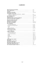
Page 3: ...CK TUNER HI FI OPERATION POWER PRINTED CIRCUIT BOARDS SYSCON OPERATION DECK SYSCON OPERATION SCHEMATIC DIAGRAMS Y C AUDIO CCD HEAD AMP SYSTEM CONTROL SERVO TUNER POWER OPERATION HI FI DECK INTERCONNEC...

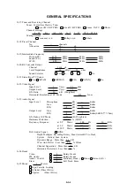
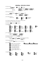
Page 4: ...nch G 9 Tape Speed NTSC or PAL M PAL or SECAM SP 33 35 mm sec SP 23 39 mm sec LP 16 67 mm sec LP 11 69 mm sec SLP 11 12 mm sec G 10 Recording Playback Time NTSC or PAL M at SP Mode Max 210 min with T...

Page 5: ...p 75 ohm S N Ratio 50 dB Weighted Horizontal Resolution at SP Mode 230 Lines G 23 Audio Signal Input Level Microphone dB Kohm Line dB Kohm RCA 8 dB 50 Kohm Output Level Line dB Kohm RCA 8 dB 1 Kohm 0...

Page 6: ...DEMKO IEC65 CNS SISIR SEMKO NZ HOMOLO SABS GOST NOM AS3159 DENTORI UNE NONE Radiation FCC DOC PTT CE SEV SABA SI NZ HOMOLO UNE CNS CISPR13 DENTORI AS NZS NONE G 35 Temperature Operation 5 C 40 C Stor...

Page 7: ...R T Rec Pause CH AV Clock Memory Pin Code Tape Counter Index Hotel Lock Tape Speed Tracking Hi Fi Tape In Repeat Dirty Head G 42 OSD Language Eng Ger Fre Spa Ita Por Jan OSD Language Setting Eng Ger F...

Page 8: ...Search CH Auto Set Up Auto Clock ATS VIDEO PLUS SHOWVIEW G CODE PDC HQ VHS Standard High Quality VPS Auto Power On Auto Play Auto Rewind Auto Eject Auto Power Off Premiere Canal Full OSD Forward Reve...

Page 9: ...r 1 Ch Down Eject 2 Input Select Play 3 Audio Select Stop 4 TV VCR F FWD 5 Pause Still Rew 6 Slow Timer Rec 7 Slow Speed Up REC OTR 8 Slow Speed Down Auto Tracking 9 Skip Search Tracking Up Menu Speed...

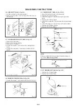
Page 10: ...llowing connectors CP1001 CP1002 CP1003 CP4001 CP4002 and CP4003 Remove the Deck Chassis in the direction of arrow 1 2 3 4 1 2 FLAP Refer to Fig 1 2 1 2 Open Flap to 90 and flex in direction of arrow...

Page 11: ...assis Main Chassis Cassette Side L Cassette Side R Locker R Fig 2 4 2 5 CASSETTE SIDE L R Refer to Fig 2 5 Unlock the 4 supports 1 and then remove the Cassette Side L R 1 Screw Torque 5 0 5kgf cm B2 1...

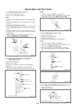
Page 12: ...upports 2 and remove the Tension Band Ass y Unlock the support 3 and remove the Tension Holder Remove the SS Brake Spring Remove the SS Arm Brake 1 2 3 4 5 6 7 8 1 2 1 Loading Motor Ass y Link Lever M...

Page 13: ...Spring Remove the screw 1 Unlock the 2 supports 2 and remove the Cassette Opener Remove the Pinch Roller Block Pinch Roller Arm Spring Pinch Roller Lever Ass y and P5 3 Arm Ass y 1 2 3 4 1 2 2 P5 Spri...

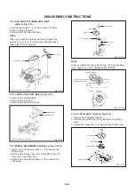
Page 14: ...tan DD Unit 1 2 3 Screw Torque 5 0 5kgf cm Fig 2 16 2 17 MIDDLE GEAR MAIN CAM Refer to Fig 2 17 A Remove the Polyslider Washer 1 then remove the Middle Gear Remove the E Ring then remove the Main Cam...

Page 15: ...e the Loading Gear Spring 2 When you install the Clutch Actuator install as shown in the circle of Fig 2 19 C Refer to Fig 2 19 C Fig 2 19 C Clutch Actuator NOTE Do not touch the roller of Guide Rolle...

Page 16: ...op Frequency Generator Front Loading Switch Frequency Modulation Frequency Sub Carrier Forward Generator Ground High Pass Filter I K L M N O P R S H SW Hz IC IF IND INV KIL L LED LIMIT AMP LM LDM LP L...

Page 17: ...or Separation Transistor Tracking Trick Playback Test Point Unregulated Volt Voltage Controlled Oscillator Video Intermediate Frequency Vertical Pulse Voltage Display Video Playback Variable Resistor...

Page 18: ...IC Refer to the NOTE FOR THE REPLACING OF MEMORY IC Initialization of the factory NOTE Do not use this for the normal servicing While pressing the CH UP key on the set press the FF key on the set for...

Page 19: ...rubber and parts which the rubber touches Replace when rolling becomes abnormal Clean the Head C3 1 CONFIRMATION OF USING HOURS PLAY REC total hours can be checked on the TV Monitor Total hours are di...

Page 20: ...zontally Clean the full erase head in the same manner Refer to the figure below Audio Control Head 2 TAPE RUNNING SYSTEM When cleaning the tape transport system use the gauze moistened with isopropyl...

Page 21: ...he SET or keys on the remote step through the ADDRESS until required ADDRESS to be changed is reached Press ENTER to select DATA When DATA is selected it will blink Again step through the DATA using S...

Page 22: ...odel JG001T X Value Adjustment For 2 heads model JG001B Monoscope 6KHz For 4 heads model JG001I Color Bar 1KHz For 4 heads model JG001P Hi Fi Audio For 4 heads Hi Fi model JG001S X Value Adjustment Fo...

Page 23: ...djustment Jig JG024A A Cut Position Fig 1 2 B B Tension Adjust 1 3 CONFIRMATION OF PLAYBACK TORQUE AND BACK TENSION TORQUE DURING PLAYBACK Load a video tape T 120 recorded in standard speed mode Set t...

Page 24: ...justed precisely at the factory Adjustment is not necessary as usual When you replace the parts of the tape running mechanism because of long term usage or failure the confirmation and adjustment are...

Page 25: ...he Guide Roller Refer to item 2 1 Confirm and adjust the Audio Control Head Refer to item 2 2 Connect CH 1 of the oscilloscope to TP4001 CH 2 to TP1002 and CH 3 to HOT side of Audio Out Jack Playback...

Page 26: ...MECHANISM ADJUSTMENT PARTS LOCATION GUIDE 5 6 7 8 9 10 1 2 3 4 1 Tension Adjust 2 Tension Arm 3 Guide Roller 4 P1 Post 5 Audio Control Head 6 7 8 9 10 X value adjustment driver hole P4 Post T Brake S...

Page 27: ...1 1 B Read and perform this adjustment when repairing the circuits or replacing electrical parts or PCB assemblies 1 BASIC ADJUSTMENT 1 2 3 4 D2 1 Connect CH 1 on the oscilloscope to TP1002 and CH 2...

Page 28: ...2 ELECTRICAL ADJUSTMENT PARTS LOCATION GUIDE SYSCON PCB TU6001 T501 VR1001 ELECTRICAL ADJUSTMENTS D2 2 J4201 TP4201 TP1001 TP1002 TP4001...

Page 29: ...KIL FM AGC DELAY PB FM EQ PB PHASE EQ P R C LPF GCA B UP AMP ACC AMP Main CONV 3 58M BPF2 AUTO BIAS P R KIL B D PB AMP 3 58M BPF1 DOUBLE LIM FM DEM SUB LPF V I CONV P R Y LPF YNR COMB N L DEEM NC1 Y...

Page 30: ...EC EE PB 85 H AMP SW 29 TRICK_PB H EE H DUMMY_V SYNC C ROTARY H SW AUDIO_MUTE H REC EE PB H AMP_SW ENV DET V REC ST H 56 14 CV IN 43 ENV DET V REC_ST H OSD_V CTL H 31 CTL H 32 CTL CTL DOC_XO_CTL 100 I...

Page 31: ...CON SERVO DECK HI FI 2 22 RF_CONV_A OUT 3 6 12 11 AUDIO_OUT_L TV VCR SYSCON SERVO DECK 16 P CON 12V HI FI FRONT JACK J4203 2 4 FRONT_V_IN TUNER_V E 5 E 6 4 14 13 4 6 7 Y C AUDIO CCD HEAD AMP FRONT_A_I...

Page 32: ...O_OUT_L HIFI_H SW RF_CONV_A OUT TUNER_A AUDIO_MUTE H V REC_ST H HIFI_ENV DET IIC_CLK IIC_DATA AUDIO_OUT_R ST_SELECT FRONT_A_IN L FRONT_A_IN R HF2 HF_COM HF1 FROM_NORMAL_A TO_NORMAL_A TUNER SYSCON SERV...

Page 33: ...1 Q503 Q510 POWER_FAIL SYSCON SERVO DECK CONTROL PHOTO COUPLER SW T501 12 13 11 4 5 IC501 KIA431 VOLTAGE CTL IC 1 2 PHOTO COUPLER L501 AC IN Q509 POWER_ON L D505 D508 D523 D528 2 9 10 Q512 P CON 12V S...

Page 34: ...3 SW607_3 SW603_3 SW605_3 SW608_3 SW606_3 D511 R511 R514 Q502 D1003 C508 L4001 IC501 TP4201 W129 L6001 W052 W061 W103 J4203 W140 W059 R1054 W125 W126 C6003 R1013 W142 W141 C505 C4050 W136 C4038 W143 W...

Page 35: ...R1023 R4211 R4210 C5503 R5503 C1009 C1008 C1010 C1011 R1006 C1033 C1025 C1023 R1051 C1019 C1021 R4060 C4053 C4052 C4056 C4049 C4041 C4025 C4020 C4018 Q4003 C4005 C4006 R4020 C4009 C4003 C5540 C5546 C5...

Page 36: ...7 58 59 6 60 61 62 63 64 65 66 67 68 69 7 70 71 72 73 74 75 76 77 78 79 8 80 81 82 83 84 85 86 87 88 89 9 90 91 92 93 94 95 96 97 98 99 TUNER VIDEO SIGNAL CP4002 IMSA 9604S 06Z13 1 2 3 4 5 6 CP4001 TO...

Page 37: ...VIDEO_OUT TUNER_L POWER_FAIL POWER_FAIL AC MODEVCC POWER_ON L AT 5V M CON P CON 5V AT 5V AT 12 6_V 4FSC C SYNC GND LDM F F R LDM R AUDIO_MUTE H V REC_ST H SENS_LED CAP_LIMIT CYL_DRIVE REC_LED T REC_LE...

Page 38: ...R4206 390 R4209 75 R6005 22K R6006 10K R4211 2 7K R4207 2 7K 1 4W R6008 1K R6009 1K R6010 270 1 4W R4212_1 390 R4201_1 470 1 4W R4204 10K R4205 10K C6001 22P CH C4204 470P B C4203 470P B C6004 0 01 B...

Page 39: ...E VUE SECURITE ETANT LES PIECES REPAREES PAR UN ATTENTION CAUTION DIGITAL TRANSISTOR W835 Q502 2SD734 CONTROL Q509 2SD1246 P CON 5V SW Q503 2SC4160 OEC YAC1 SWITCHING Q512 2SD734 P CON 12V SW C503 100...

Page 40: ...P601 IMSA 9604S 04Z13 FRONT 2 3 1 2 3 4 CP651 IMSA 9604S 04Z14 FRONT 2 3 1 2 3 4 W833 R607 3 3K R605 13K R604 6 8K R603 3 9K R602 2 7K R601 3 3K R658 560 R659 560 R657 560 R660 560 1 4W OF PRINTING AN...

Page 41: ...E LATEST AT THE TIME DURING PLAYBACK MEASURED WITH THE DIGITAL TESTER NOTE THE DC VOLTAGE AT EACH PART WAS FSC IIC_CLK P CON 5V P CON 5V IIC_DATA TUNER_A AUDIO_MUTE H FRONT_A_IN R FRONT_A_IN L AUDIO_O...

Page 42: ...PIECES N UTILISER QUE CELLS DECRITES DANGEREUSES AN POINT DE VUE SECURITE ETANT LES PIECES REPAREES PAR UN ATTENTION Q101 RPT 38PB113 BOT SENSOR OF PRINTING AND SUBJECT TO CHANGE WITHOUT NOTICE NOTE T...

Page 43: ...03 Vout 4 CH 3 CH RF SW SW6001 CP501 KEY B KEY A KEY B KEY A UN4001 CYLINDER UNIT ASS Y M2001 CAPSTAN DD UNIT ASS Y INTERCONNECTION DIAGRAM EP LP HEAD SP HEAD VEX905 VMX181 AUDIO IN R AUDIO IN L VIDEO...

Page 44: ...ematic diagram NOTE SYSCON SERVO 3 PB 200mV 1ms div 8 PB 1V 0 5ms div 13 PB 1V 0 2s div Y C AUDIO CCD HEAD AMP 1 PB 1V 0 2ms div 2 POWER ON 100mV 0 1 s div 4 PB 200mV 0 5ms div 5 REC 20V 5 s div 6 PB...

Page 45: ...WAVEFORMS 16 PB 1V 5ms div HI FI H 2 NOTE The following waveforms were measured at the point of the corresponding balloon number in the schematic diagram...

Page 46: ...XPLODED VIEW PCB270 OPERATION PCB 618 617 619 I 1 701 606 607 609 604 608 605 603 602 601 609 611 701 610 612 613 615 616 PCB010 SYSCON PCB TU6001 J4201 T501 621 J4203 620 705 705 705 705 702 704 702...

Page 47: ...11 509 329 330 502 502 PCB550 DECK PCB ASS Y 303 AA AD AD AD AD AA AD AD AA AA AB AB AD AD BA AA 352 503 503 367 501 356 317 369 309 355 Applying positions AA AB AC AD and BA for the grease or oil are...

Page 48: ...A AA AD AD AA AA AA AA AA AC AA 307 354 326 327 322 513 350 308 337 AA 325 AD AA AD NOTE Applying positions AA AB AC AD and BA for the grease or oil are displayed for this section Check if the correct...

Page 49: ...2WSA0192 SHIELD CASE HEAD AMP ASS Y 614 800WR00071 RUBBER SYSCON 8x15xT17 5 615 753WSA0124 SHIELD COVER HEAD AMP 616 755WPA0015 PLATE COVER POWER 617 702WSA0059 PLATE BOTTOM 618 702WPA0646 PLATE JACK...

Page 50: ...Y S M2001 1510398030 CAPSTAN DD UNIT F2QSB02 M2003 1589311005 MICRO MOTOR F2OEL82 320 85OA400178 PINCH ROLLER LEVER ASS Y PCB550 A4C831B550 DECK PCB ASS Y VE8851 321 85OA600188 BRAKE T ASS Y S Q101 00...

Page 51: ...A G3 SW6001 0501201010 SWITCH SLIDE SSAB110100 D1004 D2LXE65800 DIODE SILICON 1N4005E G23 VARIABLE RESISTOR D1005 D2LXE65800 DIODE SILICON 1N4005E G23 VR1001 V126314BTC VOLUME SEMI FIXED RH063MC14R D1...

Page 52: ...BON RESISTOR CAPACITORS CC CERAMIC CAPACITOR CE ALUMI ELECTROLYTIC CAPACITOR CP POLYESTER CAPACITOR CPP POLYPROPYLENE CAPACITOR CPL PLASTIC CAPACITOR CMP METAL POLYESTER CAPACITOR CMPL METAL PLASTIC C...

Page 53: ...M4C9 A6B B024009 SPEC NO O R NO...

Reviews: