background image

DNB Loader

Part No.: H-020-000137-00

MGIDL-T7RS

MGI-service@mgi-tech.com

E-mail:

Building 24, Stage 3.1, BioLake Accelerator, No.388, 2nd Gaoxin Road, East Lake 
High-Tech Development Zone, 430075, Wuhan, P.R.China

www.mgi-tech.com

Website:

Address:

W u h a n   M G I   T e c h   C o . ,   L t d .

Research Use 

Only

Version: 3.0

Summary of Contents for MGIDL-T7RS

Page 1: ... service mgi tech com E mail Building 24 Stage 3 1 BioLake Accelerator No 388 2nd Gaoxin Road East Lake High Tech Development Zone 430075 Wuhan P R China www mgi tech com Website Address W u h a n M G I T e c h C o L t d Research Use Only Version 3 0 ...

Page 2: ...luding but not limited to any commercial of special purpose and any reasonable implied guarantee MGI has taken measures to guarantee the correctness of this manual However MGI is not responsible for any missing parts in the manual and reserves the right to revise the manual and the device so as to improve the reliability performance or design Figures in this manual are all illustrations The conten...

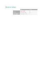
Page 3: ...Revision history Date Version Revision May 24 2022 3 0 February 22 2021 2 0 Initial release December 30 2020 1 0 ...

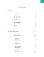
Page 4: ...iological safety 6 Symbols 6 Device 6 Label 7 Packaging 9 Device overview 11 Intended use 12 Working principle 12 Structural composition 12 Front view 13 Back view 15 Flow cell stage A 16 Flow cell 17 Plate tray unit 17 Control software 18 Self test interface 18 Main interface 19 Log interface 21 Settings interface 21 Maintenance interface 22 ...

Page 5: ...lling the device 26 Powering on or off the device 27 Powering on the device 27 Powering off the device 27 Preparing materials for post wash 27 Material list 27 Preparing the post loading plate 28 Preparing materials for loading 28 Loading 29 Workflow 30 Preparing sample libraries and materials 30 Performing a pre wash optional 30 Loading consumables 31 Performing a load 34 Performing a post wash 3...

Page 6: ... cell stage 39 Tools and solutions 39 Cleaning the flow cell stage 39 Replacing the sealing ring 40 Maintaining the software 41 Troubleshooting 41 Storage and transportation 43 Disposal of the device 44 Specifications 45 Compliance information 47 Manufacturer information 49 European representative information 51 Index 53 ...

Page 7: ... T h i s p a g e i s i n t e n t i o n a l l y l e f t b l a n k ...

Page 8: ...escribes basic safety information about the device Carefully read and understand the information before use to ensure correct operations best performance and personnel safety Keep this manual at hand for reference at any time ...

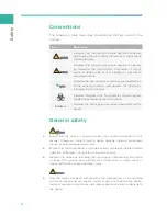
Page 9: ...uctions Boldface Indicates the printings and on screen characters on the device General safety z Ensure that the device is operated under the conditions specified in this manual Otherwise it might result in device damage incorrect experiment results or even cause personal injury z Ensure that the components of the device are completely installed before operation Otherwise it might result in person...

Page 10: ... experiment solve the problems before you restart an experiment z If you have maintenance questions that are not mentioned in this manual consult the technical support z Only the components provided by the manufacturer can be used for device maintenance Unapproved components might damage the device or degrade performance z The device is verified before delivery If serious deviation occurs during u...

Page 11: ... comply with the limits for a Class B digital device pursuant to Part 15 of the FCC Rules These limits are designed to provide reasonable protection against harmful interference in a residential installation This equipment generates uses and can radiate radio frequency energy and if not installed and used in accordance with the instructions may cause harmful interference to radio communications Ho...

Page 12: ... appareil doit accepter tout brouillage radioélectrique subi même si le brouillage est susceptible d en compromettre le fonctionnement La distance entre l utilisateur et de produits ne devrait pas être inférieure à 20 cm Industry Canada ICES 003 Compliance CAN ICES 3 B NMB 3 B Mechanical safety To avoid falling off and personal injury place the device on a level surface and ensure that the device ...

Page 13: ...nto eyes immediately flush the affected area with large amounts of water and get medical aid immediately z Use and store the reagents according to the reagent kit user manual Failure to do so might negate the reagent effects and cause inaccurate results z Check the expiration date of all reagents before use Do not use expired reagents z When disposing of the expired reagents waste liquids waste sa...

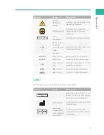
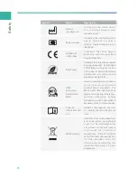
Page 14: ...wers on or off the device SOCKET Power port Connects to the mains supply LAN RJ45 network port Connects the network of the computer and server USB 2 0 port Connects to the USB device USB 3 0 port Connects to the USB device Label The following table describes symbols on the label Symbol Name Description Research Use Only Indicates a device that is for research use only and cannot be used for clinic...

Page 15: ...lectronic equipment E115163 NRTL Listing and Certification Mark Used to designate conformance t o n a t i o n a l l y re co g n i z e d product safety standards The Mark bears the name and or logo of the testing laboratory p ro d u c t c a t e g o r y s a fe t y standard to which conformity is assessed and a control number Consult instructions for use Indicates the need for the user to consult the...

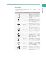
Page 16: ...om moisture Do not stack Indicates that stacking of the transport package is not allowed and no load shall be placed on the transport package Do not roll Indicates that the transport package shall not be rolled or turned over but shall remain in the upright position Temperature limit Indicates the temperature limits to which the medical device can be safely exposed Humidity limitation Indicates th...

Page 17: ... T h i s p a g e i s i n t e n t i o n a l l y l e f t b l a n k ...

Page 18: ...11 Device overview This chapter describes the intended use working principle and structural composition of the device ...

Page 19: ...tage syringe pump vacuum pump and RFID reader The following table describes functions of each component Component Description Touch screen monitor Displays the information and performs on screen operation PCR board assembly Controls the system drives the components collects status and feeds back to the system Y Z motion stage Switches among different reagents Flow cell stage Connects the fluidics ...

Page 20: ...iption 1 Touch screen monitor Facilitates the on screen operation and displays information 2 Flow cell compartment Holds the flow cell 3 Flow cell compartment door Pushes it right or left to open or close the flow cell compartment door 4 Loading compartment Places the post loading plate and load the liquid ...

Page 21: ...rning appears z Red an error occurs 7 RFID scanning area Identifies the ID of the item placed near the area 8 Ventilation outlet Ventilates the device 9 USB port panel Connects to the USB devices such as mouse and keyboard 10 Power port Connects to the mains supply Fuses are installed in the port 11 Power switch Powers on or off the device z Switch to the position to power on the device z Switch t...

Page 22: ...Structural composition 15 Back view 1 2 Figure 2 Back view No Name Description 1 Ventilation outlet Ventilates the device 2 Supporting feet Supports the main unit to ensure stability ...

Page 23: ...cription uses flow cell stage A as an example No Name Description 1 Flow cell attachment button A Press to activate the vacuum for attachment or release of the flow cell 2 Aluminum chuck Loads and attaches the flow cell 3 Sealing ring 4 Alignment groove Used for aligning with the flow cell ...

Page 24: ...cription 1 Label location Posts the label of the flow cell Plate tray unit 2 1 Figure 5 Plate tray unit No Name Description 1 DNB tube hole Holds the DNB tube 2 Plate tray Holds the post loading plate and brings it to the specified position while Y Z motion stage moves ...

Page 25: ...e flow cell Wash Performs wash and maintenance for the fluidics lines of the system Self test interface After you power on the device self test starts If the self test succeeds the main interface appears If the self test fails perform the following steps 1 In the main interface tap and select Log to check the detailed self test results that are recorded in the log 2 Follow the on screen instructio...

Page 26: ...es the following areas No Name Description 1 Icon and button area Displays the icon and buttons 2 Operation area Select a flow cell stage and perform the relevant operations If you select flow cell stage A the main interface A appears Loading Wash A Idle x xx kPa x xx C A B Figure 7 Main interface A ...

Page 27: ...ys the local date and time Tap to return to the main interface Zlims Displays the connection status of the device and the server that ZLIMS is installed on Tap to view prompt details The prompt icon includes the following status z Yellow a warning appears z Red an error occurs Menu button You can tap this button to view logs change system settings perform system maintenance shut down or restart th...

Page 28: ... Log The following table describes the function of controls in the interface Item Description Tap to exit the log interface and return to the previous interface All Tap to view all types of logs Info Tap to view information type logs Warning Tap to view warning type logs Error Tap to view error type logs Tap to select the date in the pop up calendar Flow cell Select the check box to view the logs ...

Page 29: ...maintenance interface tap and select Maintenance The following table describes the function of controls in the interface Item Description Self test Tap to perform a self test for the hardware of the device The result of each item is displayed in the interface After self test you will be prompted that the self test is successful Empty fluidics line A B Tap to discharge the residual liquid in its fl...

Page 30: ...23 Getting started This chapter describes laboratory preparations and loading preparations ...

Page 31: ...device should be used with the ultra pure water machine and refrigerator and can be used with the genetic sequencer Therefore enough space should be considered when placing the above instruments z Ensure that enough space is provided around the device for ventilation cable connection and power switch operation The following figure indicates distances that are required for optimal operation and acc...

Page 32: ...ivirus software contact the technical support in advance Data and device ports z RJ45 Network port connects to the network of the computer and server z USB ports connects to the keyboard mouse or other devices The keyboard and mouse are optional and should be purchased separately Inspecting the device z Only the technical support of the manufacturer or trained personnel can unpack the device Conta...

Page 33: ... label Remains unaffected Indicates that no tilt occurs or the gradient does not exceed the limit Red Indicates that tilt occurs and the gradient exceeds the limit Preparing the power supply Item Description Voltage and frequency range 100 V 240 V 50 60 Hz Voltage fluctuation 10 Grounding resistance 4 Ω Rated power 600 VA The available current should be equal to or greater than 10 A Transient over...

Page 34: ...rd or under the guidance of the experienced electrician z We recommend that you use the power cord provided by the manufacturer to connect to the power supply and the power cord can be only used with this device Failure to do so might damage the power cord or device Powering on the device Perform the following steps 1 Connect the power port of the device and the mains supply socket by using the po...

Page 35: ...loading plate 2 Add 4 mL of 0 1 M NaOH that is used for washing to well 11 by using the pipette Figure 9 Adding 0 1 M NaOH 3 Place the prepared post loading plate close to the device Preparing materials for loading Prepare the following items z Post loading plate z DNB tube z Sequencing flow cell z DNBs for preparation methods refer to the reagent kit user manual ...

Page 36: ...29 Loading This chapter describes the loading workflow and wash procedures The following description uses flow cell stage A as an example Read and follow the instructions to ensure correct operations ...

Page 37: ...ies and materials Refer to Preparing materials for loading on Page 28 Performing a pre wash optional If the device is not in use for one week or longer perform a pre wash before use Perform the following steps 1 Prepare the washing plate for pre wash For details refer to the reagent kit user manual The washing plate is delivered with the device Before each use clean the washing plate with the labo...

Page 38: ...ns and safety standards of your laboratory 8 Empty any remaining washing solution in the washing plate into an appropriate waste container Dispose of the waste according to local regulations and safety standards of your laboratory We recommend that you dispose of the washing plate after three months of continuous use Loading consumables DNB ID Post loading plate ID Flow cell ID Load post loading p...

Page 39: ... is placed in the wrong direction 3 5 Figure 11 Loading the post loading plate and DNB tube 4 Tap the DNB ID box and input the DNB tube ID with the on screen keyboard 5 Load the DNB tube into the DNB tube hole of the plate tray in the direction of the arrow shown in the following figure After that you will be prompted that the DNB tube is loaded NOTE Press the DNB tube gently to ensure that the tu...

Page 40: ...ed After the flow cell is securely seated do not move it again Moving the flow cell might cause the sealing rings to misalign with holes of the fluidics line z If the flow cell is not attached properly wipe the flow cell stage and the back of the flow cell with a clean cloth moistened with 75 ethanol and then let it air dry Do not press the glass because it might bring particulate matters and fing...

Page 41: ...mpts If errors occur a message appears on the screen Follow the prompt to troubleshoot and solve the problem For information about the troubleshooting refer to Troubleshooting on Page 41 If the problem persists contact the technical support In the loading consumables interface tap Start and a confirmation dialog box appears Select Yes to start loading The remaining time for loading appears in the ...

Page 42: ...w cell 4 Hold the flow cell by left and right edges and remove the flow cell NOTE The prepared flow cell can be used for sequencing If the flow cell is not used immediately store the flow cell at 4 C for up to one week Performing a post wash Chemicals in reagents and waste might cause personal injury through contact with the skin eyes and mucosa Follow the safety standards of your laboratory and w...

Page 43: ...m temperature The washing flow cell can be reused for up to three times for washing Then dispose of the flow cell according to local regulations and safety standards of your laboratory 7 Empty any remaining washing solution in the post loading plate into an appropriate waste container Dispose of the waste according to local regulations and safety standards of your laboratory Used post loading plat...

Page 44: ...37 Maintaining the device This chapter describes maintenance procedures of the device and its parts Perform maintenance regularly to ensure that the device runs smoothly ...

Page 45: ...are unknown z If you have questions about the compatibility of disinfectants contact the technical support Perform the following steps 1 Power off the device and open the loading compartment door and flow cell compartment door 2 Clean the touch screen plate tray and flow cell stage with a 75 alcohol wipe Ensure that the surface is free of DNBs reagents blood and saliva Monthly cleaning z We do not...

Page 46: ...tion before each use Re connect the cables if needed ensure that the device is powered off or contact the technical support if new cables are required Maintaining the flow cell stage Perform cleaning and maintenance for the flow cell stage before use Failure to do so might affect the attachment of the flow cell to the chuck Tools and solutions z Washing flow cell z Protective gloves z Dust free cl...

Page 47: ...ell stage Ensure that the flow cell and label are facing upward Press the edges of the flow cell with your hands to ensure that it is securely seated 6 Press the flow cell attachment button on the flow cell stage Replacing the sealing ring Use sealing rings that are supplied by the manufacturer for replacement Every three to six months replace the sealing rings of the flow cell stage When the seal...

Page 48: ...alled Maintaining the software After the receival of Release Notification contact the technical support to update the software Troubleshooting If malfunction occurs during operation the device beeps or a message appears on the screen Follow the on screen prompt to troubleshoot and solve the problem The following table lists some of the problems and possible solutions If problems that are not menti...

Page 49: ...s line o f t h e f l o w ce l l when aspirating the reagent 1 After loading press the flow cell attachment button to release the flow cell 2 C h e c k w h e t h e r t h e sealing ring is installed evenly If not re install the sealing ring 3 If the problem persists contact the technical support The flow cell cannot be attached to the flow cell stage z T h e f l o w ce l l a t t a c h m e n t b u t ...

Page 50: ...e on Page 39 3 If the problem persists contact the technical support The flow cell stage leaks z The sealing ring is not installed z The sealing ring is installed incorrectly z There are foreign objects on the rear of the flow cell z The fluidics lines are blocked 1 Check whether the sealing ring is installed 2 C h e c k w h e t h e r t h e sealing ring on the flow cell stage is intact or any fore...

Page 51: ...ice The service life of this device is seven years which is determined by the simulated service life evaluation method For the date of manufacture refer to the label on the device Perform the maintenance according to the requirements mentioned in this manual Dispose of the end of life device according to local regulations ...

Page 52: ...179 lb Touch screen monitor z Type LCD touch screen z Size approximately 13 3 inches z Resolution 1280 600 pixels Power z Voltage 100 V 240 V z Frequency 50 60 Hz z Rated power 600 VA z Overvoltage category II z Cable min 16AWG Fuse specification F10AL250V Maximum sound pressure level 75 dB Degrees of protection provided by enclosures IP Code IPX0 ...

Page 53: ...use the temperature and humidity fluctuations influence the accuracy of the loading results we recommend that you install an air conditioning system and a dehumidifier in the laboratory to maintain appropriate temperature and humidity Storage transportation environment requirements z Temperature 20 C to 50 C 4 F to 122 F z Relative humidity 15 RH to 85 RH non condensing z Atmospheric pressure 80 k...

Page 54: ...ments for electrical equipment for measurement control and laboratory use Part 1 General requirements z IEC 61010 2 081 2019 Safety requirements for electrical equipment for measurement control and laboratory use Part 2 081 Particular requirements for automatic and semi automatic laboratory equipment for analysis and other purposes z IEC 61010 2 010 2019 Safety requirements for electrical equipmen...

Page 55: ... T h i s p a g e i s i n t e n t i o n a l l y l e f t b l a n k ...
Page 56: ...anufacturer Wuhan MGI Tech Co Ltd Address Building 24 Stage 3 1 BioLake Accelerator No 388 2nd Gaoxin Road East Lake High Tech Development Zone 430075 Wuhan P R China Technical support Wuhan MGI Tech Co Ltd Technical support E mail MGI service mgi tech com ...

Page 57: ... T h i s p a g e i s i n t e n t i o n a l l y l e f t b l a n k ...
Page 58: ...European representative information 51 European representative information Name Latvia MGI Tech SIA Address Dzirnavu street 57a 4 Rīga Latvia LV 1010 ...

Page 59: ... T h i s p a g e i s i n t e n t i o n a l l y l e f t b l a n k ...
Page 60: ...hock and anti tilt labels 23 Anti shock label 24 Anti tilt label 24 B Biological safety 4 C computer 4 control software 4 D device damage 2 E electromagnetic environment 3 empty the fluidics line 20 F fluidics lines 3 fuse 4 ...

Page 61: ...Index 54 L Loading compartment 11 M Main interface 17 N Network requirements 22 P Plate tray unit 15 Power switch 12 pre run 28 R re position 3 RFID 6 RFID scanning area 12 ...

Reviews: