background image

Introduction

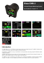
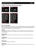
The Blaze EMS-2 is a 3  1/8” (80mm)  universal engine monitor color display instrument. The EMS-2 contains all the
necessary functionality to replace several engine monitoring instruments.

All information is displayed in an easy to read format on a high resolution wide viewing angle 2.6” 600cd/m2 sunlight
readable color display.

The EMS-2 light weight, small size and high level of functionality makes it an excellent choice for all types of engines. The
EMS-2 can also interface directly to UL Power engines via the RS232 port.

The   EMS-2   can   also   be   interfaced   via   the   CAN   bus   to   an   optional   external   RDAC   unit   (Remote   Data   Acquisition
Computer). This allows  for easier installation as the RDAC unit is normally mounted in the engine compartment.

Blaze EMS-2

Universal Engine Monitoring System

Operating Manual – English 1.10

Summary of Contents for Blaze EMS-2

Page 1: ... readable color display The EMS 2 light weight small size and high level of functionality makes it an excellent choice for all types of engines The EMS 2 can also interface directly to UL Power engines via the RS232 port The EMS 2 can also be interfaced via the CAN bus to an optional external RDAC unit Remote Data Acquisition Computer This allows for easier installation as the RDAC unit is normall...

Page 2: ...ual RPM measurement Includes a magneto check function RPM can be displayed in RPM or in percentage Records maximum RPM reached for each channel Fuel Flow Uses RPM 2 Input Single fuel flow measurement Fuel flow can be displayed in L hr or in G hr Fuel Level Analog inputs can be used to measure fuel level Fuel level can be displayed in Litres or Gallons Standard automotive fuel level senders can be ...

Page 3: ... push button Volts Can measure voltages up to 30V compatible with both 12V and 24V aircraft supplies Contains a programmable low high voltage alarm to automatically detect alternator failures and bad batteries Records maximum and minimum Volts reached in permanent memory Current RDAC connection Uses the MGL Avionics Closed Loop Current Sensor to measure the aircrafts current load Records maximum a...

Page 4: ...ic display Backlight can be adjusted in the menu system Rotary Control Up Down Enter Button Press the rotary control during the normal display screens to access the menu system Rotate anti clockwise for up down menu scrolling Rotate the rotary control during the normal display mode to view the Timers Trend Graphs and the Max Values display F1 Up Button Menu System Softkey button Normal Display Sta...

Page 5: ...ers are displayed then the EMS 2 will alternate the display at 2 second intervals EGT CHT display section The Blaze EMS 2 supports up to 4 thermocouples using the internal electronics and up to 12 thermocouples using the optional external RDAC The EGT CHT section will automatically try and maximize the display area according to the number of EGTs CHTs selected The EGT CHT parameters can be configu...

Page 6: ...t down to zero when the engine RPM is greater then the HOBBS RPM value as set in the TIMERS SETUP A good use for this function is to set the hours until your next spark plug change or engine inspection The purpose of this function is to assist you in determining remaining hours until maintenance will be required It is not intended as a replacement for the aircraft s maintenance log It is therefore...

Page 7: ...op is the result of reduced energy output from the diminished fuel flow The best operating mixture for aircraft engines is in the vicinity of this peak EGT reading The EMS 2 has a special Leaning mode which easily identifies the peak EGT condition allowing you to adjust your fuel mixture for best performance Fuel mixture should be adjusted once you have decided on a suitable cruise power setting t...

Page 8: ...p RPM The display will show the RPM deviation from when the magneto function was activated Any RPM drops will be displayed as a negative RPM value a positive reading indicates an increase in RPM Switch the mag to left or right The EMS 2 should display a negative drop in RPM Then switch the mags to Both The EMS 2 reading should go back to zero or near zero A problem should show up as an excessive d...

Page 9: ...Blaze EMS 2 Operating Manual Page 9 4 Menu System Press the rotary control button during the normal display mode to enter the menu system Use the rotary control to navigate through the menu system ...

Page 10: ...ht Timer View Flight Log Use the rotary control to view the next flight log entry Erase Flight Log Use this function to erase the flight log stored in the EMS 2 FLIGHT Select whether you want the EMS 2 to automatically detect a flight or whether the pilot must press the F1 Up button to start stop a flight We recommend you select automatic flight detection either on RPM1 or RPM2 T O RPM This menu o...

Page 11: ... give you increased display resolution Display Min Select the minimum RPM that you want the RPM dial to show This can give you increased display resolution High Alarm This enables or disables the RPM high alarm High Alarm Enter the RPM threshold for when the high alarm must be activated Any RPM value above this value will activate the alarm High Caution Enter the RPM value for the high caution Thi...

Page 12: ...ns per cylinder A four cylinder automotive four stroke engine would thus generate 2 pulses per revolution A typical Rotax DCDI two stroke engine would generate 6 pulses per revolution The well known Rotax 912 914 engine generates one pulse per revolution Increment Select the step size between successive RPM values eg if the RPM value is 4003 RPM and the RPM INCREMENT is 5 then the actual value sho...

Page 13: ...e that you want the RPM to correlate to 100 This is only shown if Percent is selected for display Display Max Select the maximum RPM that you want the RPM dial to show This can give you increased display resolution Display Min Select the minimum RPM that you want the RPM dial to show This can give you increased display resolution High Alarm This enables or disables the RPM high alarm High Alarm En...

Page 14: ...e for every two revolutions per cylinder A four cylinder automotive four stroke engine would thus generate 2 pulses per revolution A typical Rotax DCDI two stroke engine would generate 6 pulses per revolution The well known Rotax 912 914 engine generates one pulse per revolution Increment Select the step size between successive RPM values eg if the RPM value is 4003 RPM and the RPM INCREMENT is 5 ...

Page 15: ...lled You can use the K Factor to calibrate your fuel flow sender See the installation section for more details on how to calibrate and install the fuel flow sender Mode Select if you want to measure fuel flow using a fuel flow sender or by using fuel injectors Injector Select whether the EMS 2 fuel flow input is connected to the high or low side fired fuel injector Data Select the data source of t...

Page 16: ... selection between HIGHEST or SCANNING can be selected If HIGHEST is selected then the current highest thermocouple temperature is displayed If SCANNING is selected then the unit will cycle through each thermocouple at a one second interval Display Max Select the maximum temperature that you want the EGT CHT bargraph to show This can give you increased display resolution Display Min Select the min...

Page 17: ... want the temperature to be displayed in degrees Celsius ºC or degrees Fahrenheit ºF Data Select the data source of the themocouples Options include internal using the internal thermocouple amplifier and Blaze connector or from an optional external RDAC unit RDAC Address Select the CAN address of the external RDAC unit 4 5 1 Special Rotax 912 914 probe mode In this mode the Analog Channel 3 and An...

Page 18: ...e Setup Mode Select the function for the analog channel Options are PRESSURE TEMP CURRENT FUEL LEVEL or OFF Type Select if you are using a resistive voltage or current pressure sender If the RESISTIVE pressure sender is selected Sender Select what type of resistive pressure sender you are using Select VDO for VDO resistive senders USER for a custom sender Model Select which VDO pressure sender you...

Page 19: ...pe is set to USER then use this menu option to calibrate your pressure sender See section 4 2 3 for more information Label Enter a label to suit your pressure channel so you can identify it easily Unit Select whether you want to display the pressure in Bar psi or psi 0 1 The psi 0 1 is for low range pressure senders e g UMA 7PSI Display Max Select the maximum pressure that you want the bargraph to...

Page 20: ...m an optional external RDAC unit RDAC Address Select the CAN address of the RDAC unit 4 6 2 Temperature Setup Mode Select the function for the analog channel Options are PRESSURE TEMP CURRENT FUEL LEVEL or OFF Sender Select what type of sender you are using Select VDO 120 for a VDO 120 degree NTC sender Select VDO 150 for a VDO 150 degree NTC sender WESTACH for Westach 339 NTC sender MGL for a MGL...

Page 21: ...isplay resolution Display Min Select the minimum temperature that you want the bargraph to show This can give you increased display resolution High Alarm This enables or disables the temperature high alarm High Alarm Enter the temperature threshold for when the high alarm must be activated Any temperature above this value will activate the alarm High Caution Enter the temperature value for the hig...

Page 22: ...e points have been entered 5 Verify the above calibration by checking the temperature pressure or current display versus the actual applied sender stimulus 4 6 4 Current Setup requires a MGL Avionics Closed Loop Current Sensor Mode Select the function for the analog channel Options are PRESSURE TEMP CURRENT FUEL LEVEL or OFF Label Enter a label to suit your current channel so you can identify it e...

Page 23: ...gh the MGL Avionics Closed Loop Current sensor This is best done with the MGL Closed Loop Current sensor disconnected from the main current supplying conductor Gain Adjust the gain factor until the current is reading correctly It will be best if a multimeter can be inserted in series with the current supplying conductor and the gain calibration adjusted until the EMS 2 matches that of the multimet...

Page 24: ...ashing of the fuel level display and remaining fuel readout You can also connect a warning lamp to the external alarm output see installation diagram Note that the fuel low level will be displayed as a red bar on your fuel level display This level is over and above your silent fuel reserve Low Caution Enter the fuel level value for your fuel caution Note that the fuel caution level will be display...

Page 25: ...evel sender reading at 0 Lt position Move the highlight to this position and wait until the sender reading has stabilized You will see the sender ADC reading at the top This could take up to a minute so have patience ENSURE THAT THE FLOAT IS NOT SUBMERGED AND IS FLOATING ON TOP OF THE FUEL LEVEL Should this number not react to changes of your level sender position then you have a problem Please ch...

Page 26: ...fety factor for an aircraft and a very useful feature for peace of mind during cross county flights Notes on Slope error Sender value is a value determined by the EMS 2 It is used to calculate fuel level fuel endurance estimate and current range estimate The fuel tank setup sender value can e ither increase in value as fuel is added or decrease in value if fuel is added This is dependent on the ty...

Page 27: ...bargraph is only shown if the current display is disabled Display Min Select the minimum value that you want the volts bargraph to show This can give you increased display resolution The bargraph is only shown if the current display is disabled High Alarm This enables or disables the volts high alarm High Alarm Enter the voltage threshold for when the high alarm must be activated Any voltage above...

Page 28: ...he volts low alarm Low Alarm Enter the voltage threshold for when the low alarm must be activated Any voltage below this value will activate the alarm Cal Measure the battery voltage with a multimeter and then adjust this value to match that of the multimeters volts reading ...

Page 29: ...nches of mercury Display Max Select the maximum pressure that you want the manifold bargraph to show This can give you increased display resolution Display Min Select the minimum pressure that you want the manifold bargraph dial to show This can give you increased display resolution High Alarm This enables or disables the manifold pressure high alarm High Alarm Enter the pressure threshold for whe...

Page 30: ...e will activate the alarm Filter This function can be used to select the signal filter time constant Selections are NONE FAST or SLOW This selection influences the rate at which your manifold pressure can change its reading Cal The sender in the RDAC is shipped uncalibrated To calibrate the manifold pressure compare and adjust the calibration factor until the manifold reading is the same as the ba...

Page 31: ...ables the current high alarm High Alarm Enter the current threshold for when the high alarm must be activated Any current above this value will activate the alarm High Caution Enter the current value for the high caution Low Caution Enter the current value for the low caution Low Alarm This enables or disables the current low alarm Low Alarm Enter the current threshold for when the low alarm must ...

Page 32: ...sconnected from the main current supplying conductor Gain Adjust the gain factor until the current is reading correctly It will be best if a multimeter can be inserted in series with the current supplying conductor and the gain calibration adjusted until the EMS 2 matches that of the multimeter Please see the MGL Avionics Closed Loop Current Sensor documentation for more information RDAC Address S...

Page 33: ...rements RTC Trim This allows you to adjust a trimming factor that will increase the accuracy of the built in clock SET HOBBS TIME This function allows you to set the engine Hobbs meter to any value Typically you would use this function to set the Hobbs meter to the current known engine time Use the rotary control to change the value Press the rotary control to accept and exit the menu option If th...

Page 34: ...AINT TIMER This function allows you to set an engine maintenance timer This timer is set in engine hours and it will count down to zero when the engine RPM is greater then the HOBBS RPM A good use for this function is to set the hours until your next spark plug change or engine inspection Use the rotary control to change the value H M Start Select what source will start the Hobbs and Maintenance t...

Page 35: ... Select the ECU that is connected to the EMS 2 Select NONE for standard RDAC functionality ROTAX 912is or UL POWER 4 11 1 ROTAX 912is Setup MGL Avionics RDAC CAN required The Rotax ECU transmits various status messages These can be observed in the Rotax 912is main display pages ...

Page 36: ...AY 2 10 0 bar ADC 2 4095 Oil Temperature Analog Channel 2 FUNCTION TEMP SENDER LM335 LM335 0 Coolant Temperature Analog Channel 3 FUNCTION TEMP SENDER LM335 LM335 0 EGT 1 2 3 4 EGT CHANNELS 4 Throttle Position 0 100 is displayed as a bar graph Engine Ambient Pressure This can be viewed in the Engine Info display screen Fuel Level sender Analog Channel 4 This is setup as normal in the analog setup ...

Page 37: ...egrees Fahrenheit ºF UL Power display screen A dedicated display screen will be shown when the UL Power is selected for the ECU type Alternating Display Area Oil pressure Oil Temperature Fuel Pressure OAT Throttle position ECU temperature air temperature Volts and optional current is displayed here Warning Messages from the UL Power ECU RPM Fuel Flow Ignition 1 Indicator Green On Red Off Alternati...

Page 38: ...he EMS 2 also supports the UL Power Aux box UL Power recommended settings Oil Pressure max 8 bar 115psi normal 2 to 5 bar 30 75 psi above 2000rpm minimum 0 7 bar Oil Temperature Max 120 C 248 F Min 50 C 122 F Normal between 80 C and 100 C 175 F 212 F Fuel Pressure max 3 8 bar 55psi normal 3 bar 43 5 psi minimum 2 4 bar 35 psi Map Max 1 1 bar 33 inch kg Min 0 3 bar 9 inch kg EGT max 860 C 1580 F Mi...

Page 39: ...enu 4 12 1 Protocol Format STX Address Message type Length Data payload Checksum ETX STX Start of text 0x02 Address unsigned char 8bit Unit address range 0 255 Message Type unsigned char 8bit Specifies the message type Length unsigned char 8bit Length of the data payload does not include the STX Address message type checksum or ETX Data payload Data Checksum unsigned char 8bit XOR of all bytes sta...

Page 40: ...t 16 bit RPM 1 value in percentage RPM 2 Unsigned Long 32 bit RPM 2 value RPM 2 Unsigned Int 16 bit RPM 2 value in percentage Analog Channel Type Unsigned Int 16 bits CH4 4 bits CH3 4 bits CH2 4 bits CH1 4 bits 0 Off 1 Pressure 2 Temperature 3 Current 4 Fuel Level Analog Channel 1 Signed Int 16 bits Pressure in 0 1psi Temperature in Degrees C Current in 0 1A Fuel Level in Liters Analog Channel 2 S...

Page 41: ...es Celsius TC4 Signed Int 16 bit Thermocouple channel 4 in Degrees Celsius TC5 Signed Int 16 bit Thermocouple channel 5 in Degrees Celsius TC6 Signed Int 16 bit Thermocouple channel 6 in Degrees Celsius TC7 Signed Int 16 bit Thermocouple channel 7 in Degrees Celsius TC8 Signed Int 16 bit Thermocouple channel 8 in Degrees Celsius TC9 Signed Int 16 bit Thermocouple channel 9 in Degrees Celsius TC10 ...

Page 42: ...ht mode The display will set the backlight to the dim setting if the ambient light is less then the threshold setting alternatively the display will set the backlight to the bright setting if the ambient light is greater then the threshold setting The ambient light received is shown as the ADC value in the top header Use this value to set the threshold value Security Setup Select this menu option ...

Page 43: ... Values This menu displays the ADC values of the various sensors 5 Loading factory default settings Press and hold the F1 Up button and rotary control during power up to load the pre programmed factory default settings The following screen will be displayed Factory default settings can also be loaded in the Miscellaneous setup menu ...

Page 44: ...imer CRC error Try entering new values for the Hobbs meter and Maintenance timer and see if the error message disappears If the error message still persists then it could possibly be a non volatile memory failure in which case the instrument will then have to be returned to the factory Calibration constants CRC error The instrument could possibly have a non volatile memory failure in which case th...

Page 45: ...ow input RF noise filter plus Schmitt trigger based input External pull up resistor may be required Sensor Output Voltage 5Vdc Max 50mA Thermocouples Type J type K type and E Type Measurement range EMS 2 Internal amplifier K Type 100ºC to 1200ºC 148ºF to 2192ºF J Type 100ºC to 1100ºC 148ºF to 2012ºF E Type 100ºC to 800ºC 148ºF to 1472ºF Technology Fully cold junction compensated using a precision ...

Page 46: ...perature sender MGL Precision LM335 semiconductor Based on ON Semiconductors LM335 temperature sensor Westach Resistive Senders Westach 399 thermistor series temperature senders User defined senders The EMS 2 has a user sender calibration feature that can be customized for senders not listed above Fuel Level Sender Input Fuel level input Maximum voltage 5V 5mA maximum current Fuel level senders su...

Page 47: ...ontacts of several Stratomaster instruments in parallel should this be desired To avoid false activation of the alarms the alarm function is only active 10 seconds after the instrument has powered up 9 Firmware Upgrading The EMS 2 can be upgraded in the field by connecting the RS232 port to a PC and running the firmware update program Note that only the RS232 port can be used to upgrade the firmwa...

Page 48: ...f an external 1A fuse is recommended Connect the supply terminals to your aircrafts power supply The EMS 2 can be used on both 12V and 24V without the use of any pre regulators Ensure that the supply voltage will not drop below 8V during operation as this may result in incorrect readings ...

Page 49: ...s Temperatures are considerably lower so most thermocouple cables will work without problems The biggest area of concern should be the connection of the thermocouple cable to the washer This often breaks after the spark plug has been changed a few times Choose a probe that is suitably reinforced at this point for a long and trouble free life EGT and CHT probes supplied by MGL Avionics are of the h...

Page 50: ...ts can be used with signals from about 5Vpp to as much as 100Vpp The input is also AC coupled for easy installation A noise filter is included that results in the input ignoring any high frequency noise signals as long as this is below the detection threshold of about 2 5Vpp Please see dipswitch settings below The input impedance of the rev counter input is approximately 10Kohm You can use series ...

Page 51: ... and white yellow One of the two wires needs to be connected to ground engine block and the other to the RPM input 1 Insert ballast resistor Rotax 914 Connect the rev counter wires blue yellow and white yellow One of the two wires needs to be connected to ground engine block and the other to the RPM input 1 Insert ballast resistor Engines with magnetos UMA Tach Sensor T1A9 1 Slick T1A9 2 Bendix Co...

Page 52: ...nic ignition system with conventional ignition coil Use the tacho line if your system has such a signal Connect rev counter input of EMS 2 to this line Ensure you have a connection from the EMS 2 ground to the engine block Connect rev counter input of EMS 2 to this line Ensure you have a connection from the EMS 2 ground to the engine block ...

Page 53: ...stallation detects the passing of a magnet suitably fixed to prop flanges or shafts Gear tooth sensor The gear tooth sensor is a popular pickup used on the pre rotation gear of a gyro plane rotor speed indication Optical Reflective Pickup The optical reflective pickup can provide a simple means of contactless RPM sensing in difficult installations ...

Page 54: ...pull up resistor dip switch for the resistive temperature sender input must be in the ON position Connect the green wire to ground and the red wire to the analog input channel Westach Resistive senders The EMS 2 supports the Westach 399 series senders The internal pull up resistor dip switch for the resistive temperature sender input must be in the ON position User defined senders The EMS 2 has a ...

Page 55: ...ds The black lead is not to be connected and has no function The Red lead from the sensor has to be connected to the positive bus via a fuse or circuit breaker The white lead Output signal has to be connected directly to the EMS 2 analog input channel The supplied 100Ohm 1 4W resistor must be connected across the analog input channel to ground The internal pull up resistor dip switch for the 4 20m...

Page 56: ... 2 Set your fuel level to 50 Litres 3 Fly your aircraft for a period that you know will use approximately 20 Litres of fuel The exact fuel burn is not important just burn about 20 Litres of your fuel At the end of your flight the instrument should give you a reading of how much fuel you have left the reading should be about 30 Litres left 4 Now place your aircraft in exactly the same position that...

Page 57: ...d Calibration Factors for the MGL Avionics dual range flow sender With jet installed 7000 Recommended for flow rates below 30 Litres hour maximum Without jet installed 1330 Recommended for flow rates above 30 Litres hour Please refer to the leaflet included with the flow sender for information on pressure drop versus flow rate wetted materials etc It is your responsibility to ensure that the flow ...

Page 58: ...ll up to 5V Please note that capacitive senders may exhibit large errors as they are very sensitive to the composition of the fuel used We do not recommend using capacitive senders with automotive fuels for this reason Safety Hazard Please take note Be careful when installing fuel level senders into fuel tanks Ensure that the fuel tank is completely empty when you proceed with the installation Ens...

Page 59: ...ttle gas leakage will be present in a case of failure or if the instrument is removed with the engine running In the case of the 912 and 914 Rotax engines there is a pipe connecting the two manifolds where this connection can be made 10 10 OAT Probe Connect the OAT probe red wire to the EMS 2 analog input and the black or green wire to ground Dipswitch Function 1 Analog Input Channel 1 Pull up res...

Page 60: ...MS 2 Any voltage drop caused by other equipment on the ground wire will cause incorrect readings The best way to ensure a good connection is to wire a single connection between the EMS 2 ground terminal any of these terminals and the engine block Do not wire this anywhere else and do not allow any other equipment to use this wire as a current return path 10 13 External RDAC Remote Data Acquisition...

Page 61: ... routed via the engine block 3 White Blue Stripe RS232 Transmit data Firmware upgrading 4 White Black Stripe RS232 Receive data Firmware upgrading 5 Green Analog Input 2 6 Yellow RPM 2 Rotor RPM TTL signal sensor sources Fuel flow Input 7 Orange Analog Input 1 9 Red White Stripe Analog Input 4 10 Grey Analog Input 3 11 Blue RPM 1 Input Engine RPM 12 Purple CAN Low Used for optional external RDAC 1...

Page 62: ...Blaze EMS 2 Operating Manual Page 62 11 Dimensions ...

Page 63: ...alid and relevant pilot s license This person has to make themselves familiar with the operation of this instrument and the effect of any possible failure or malfunction Under no circumstances does the manufacturer condone usage of this instrument for IFR flights IMPORTANT NOTICE You must make your own determination if the products sold by MGL Avionics are safe and effective for your intended appl...

Page 64: ...ertical Speed Indicator VSI ASV 2HS Altimeter Airspeed ASI High Speed and Vertical Speed Indicator VSI EMS 2 Engine Monitoring System FF 5 Fuel Computer FLIGHT 3 Primary Flight Instrument INFO 2 Information Display G Force meter UTC and Local Time Slip Indicator Outside Air Temperature OAT Battery Voltage Current and charge display Flight Timer Flight Log Stopwatch Countdown Timer and Alarm MAG 2 ...

Reviews: