background image

Installation and Operation Manual

Important:

This  manual  contains  specifi c  cautionary  statements  relative  to  worker  safety.    Read  this  manual  thoroughly  and  follow 
as directed.  It is impossible to list all the hazards of  dust control equipment.  All persons involved with the equipment or 

systems should be instructed how to operate in a safe manner.
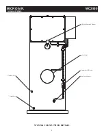
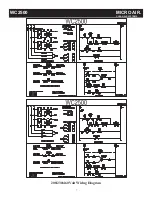
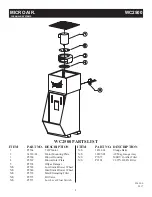
MODEL WC2500

Summary of Contents for WC2500

Page 1: ...ionary statements relative to worker safety Read this manual thoroughly and follow as directed It is impossible to list all the hazards of dust control equipment All persons involved with the equipment or systems should be instructed how to operate in a safe manner MODEL WC2500 ...

Page 2: ...skid rails Fig 1 5 Connect the fill control valve to water source 1 2 NPT 6 Connect the offgas vent pipe to offgas vent ducting as required by local state national codes 7 Make electrical connections as shown in the wiring diagram 8 Check the blower for proper rotation direction If the blower rotates backwards interchange two of the motor supply connections L1 and L2 SUMP LEVEL SET UP 1 Shut off wa...

Page 3: ...s E button 5 Press Menu button Fill Valve Operation The fill valve is normally closed and only open when signaled from the Digi Helic and if the motor has been running for longer than 30 seconds In the event of a loss of power the fill valve is designed to remain in the closed position Interlocks Low level and motor running N O interlocks are provided in the control box of the unit to interface with...

Page 4: ...NAL HEPAAFTER FILTER INSTALLATION 1 Remove the bolts and washers from the exhaust grille 2 Remove the exhaust grille 3 Place Hepa filter support Hepa filter and Hepa filter enclosure on top of the WC2500 4 Align the holes of the Hepa filter enclosure with those on the blower cabinet 5 Insert bolts and washers and tighten until secure ...

Page 5: ...r housing on top of the WC2500 4 Align the holes of the A frame filter enclosure with those on the blower cabinet 5 Insert bolts and washers and tighten until secure 6 Connect the 1 4 clear tubing from the Magnehelic high pressure port to the barb on the rear of the A Frame housing 7 Connect the temperature probe to the top rear of the A frame housing in the provided hole if ordered Magnehelic Barb...

Page 6: ...MICRO AIR WC2500 CLEAN AIR SYSTEMS Offgas Motorized Damper Automatic Fill Valve Drain Port Inlet Collar Overflow Port Low Level Sensor WC2500 CONNECTION DETAIL 6 ...

Page 7: ...208 230 460 Volt Wiring Diagram 7 WC2500 MICRO AIR CLEAN AIR SYSTEMS ...

Page 8: ...ower Housing 4 P2567 Blower Inlet Plate 5 P2574 Offgas Damper N S P2565 Low Static Blower Wheel N S P2548 Med Static Blower Wheel N S P2572 Mist Elimnating Filter N S P2573 Fill Valve N S P2571 Low Level Float Switch ITEM PART NO DESCRIPTION N S 34532 01 Sludge Rake N S 38295 03 AF Mag Gauge Assy N S P7073 MERV 16 After Filter N S P2101 99 97 HEPA Filter ...

Reviews: