
T2
T1
T2
T2
T1
T1 + T2
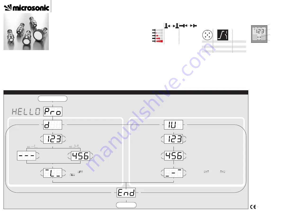
Set detect distance in
mm or cm
For single detect
point press T2
until »- - -« is
displayed
Choose »
« for NCC or
»
« for NOC
T1
T2
For window mode
operation set far
detect point in
mm or cm
T1 + T2
Press T1 and T2 simultaneously for about
3 s until welcome message has passed
T1 + T2
T2
T1
T1 + T2
T1 + T2
T1 + T2
T2
T1
T2
T1
T2
T1
T1 + T2
Set sensor-close window
margin in mm or cm
Choose rising (
) / falling (
)
output characteritic curve
T1
T2
T1 + T2
T2
T1
T1 + T2
T1 + T2
Set switched output
Set analogue output
Set sensor-distant window
margin in mm or cm
Ready
Start here
Set sensor parameters alternatively numerically using LED-display...
Product description
The mic+sensor with one analogue out-
put and one switched output measures
the distance to an object within the de-
tection zone contactless. A signal propor-
tional to distance is created and the
switched output is set according to the
adjusted detect distance.
The sensor automatically detects the load
put to the analogue output and switches
to current output or voltage output re-
spectively.
All settings are done with two push-but-
tons and a three-digit LED-display
(TouchControl).
Light emitting diodes (three-colour LEDs)
indicate all operation conditions.
Choosing between rising and falling out-
put characteristic as well as output func-
tion NOC and NCC is possible.
The sensors are adjustable manually using
the numerical LED-display or may be trai-
ned using Teach-in processes.
Useful additional functions are set in the
Add-on-menu.
Using the LinkControl adapter (optional
accessory) all TouchControl and additio-
nal sensor parameter settings may be
made by a Windows-Software.
Important instructions for assembly and
application
All employee and plant safety-relevant
measures must be taken prior to assembly,
start-up, or maintenance work (see operation
manual for the entire plant and the operator
instruction of the plant).
The sensors are not considered as safety
equipment and may not be used to ensure
human or machine safety!
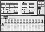
The mic+sensors indicate a
blind zone
, in
which the distance cannot be measured. The
operating range
indicates the distance of the
sensor that can be applied with normal re-
flectors with sufficient function reserve.
When using good reflectors, such as a calm
water surface, the sensor can also be used up
to its
maximum range
. Objects that strongly
absorb (e.g. plastic foam) or diffusely reflect
sound (e.g. pebble stones) can also reduce
the defined operating range.
Synchronisation
If the assembly distances shown in Fig.1 for
two or more sensors are exceeded the inte-
grated synchronisation should be used. Con-
nect Sync/Com-channels (pin 5 at the units re-
ceptable) of all sensors (10 maximum).
Fig. 1:
Assembly distances, indicating syn-
chronisation/multiplex
Multiplex mode
The Add-on-menu allows to assign an indivi-
dual address »01« to »10« to each sensor
connected via the Sync/Com-channel (Pin5).
The sensors perform the ultrasonic measure-
ment sequentially from low to high address.
Therefore any influence between the sensors
is rejected.
The address »00« is reserved to synchronisa-
tion mode and deactivates the multiplex
<10 cm
<30 cm
<1,0 m
<1,7 m
<60 cm
<1,6 m
<5,4 m
<16 m
<2,6 m
<30 m
A
B
mode. (To use synchronised mode all sensors
must be set to address »00«.)
Assembly instructions
Assemble the sensor at the installation lo-
cation.
Plug in the connector cable to the M 12
connector.
Fig. 2:
Pin assignment with view onto sensor
plug and colour coding of the
microsonic connection cable
Start-up
mic+ sensors are delivered factory made with
the following settings:
Rising analogue characteristic
Window margins for the analogue output
set to blind zone and operating range
Switched output on NOC
1
3
colour
+U
B
-U
B
brown
blue
4
2
5
D
I/U
black
white
Sync/Com.
grey
1
5
2
3
4
Detecting distance at operating range
Measurement range set to maximum range
Set the parameters of the sensor manually or
use the Teach-in procedure to adjust the de-
tect points.
Fig. 3: TouchControl
Operation
mic+sensors work maintenance free. Small
amounts of dirt on the surface do not influ-
ence function. Thick layers of dirt and caked-
on dirt affect sensor function and therefore
must be removed.
Note
mic+sensors have internal temperature
compensation. Because the sensors heat
up on their own, the temperature com-
pensation reaches its optimum working
point after approx. 30 minutes of opera-
tion.
If an object is within the set window mar-
gins of the analogue output, then LED D1
lights up green, if the object is outsite the
window margins, then LED D1 lights up
red.
The load put to the analogue output is
detected automatically when turning
supply voltage on.
During normal mode operation, a yellow
LED D2 signals that the switched output
has connected.
During normal mode operation, the mea-
sured distance value is displayed on the
LED-indicator in mm (up to 999 mm) or
cm (from 100 cm). Scale switches auto-
matically and is indicated by a point on
top of the digits. Alternatively a percent-
age scale may be set in the add-on menu.
In this connection 0% and 100% corre-
spond to the set window margins of the
analogue output.
In the »Two-way reflective barrier« ope-
rating mode, the object has to be within
the range of 0-85 % of the set distance.
During Teach-in mode, the hysteresis
loops are set back to factory settings.
If no objects are placed within the detec-
tion zone the LED-indicator shows »- - -«.
If no push-buttons are pressed for 20 se-
conds during parameter setting mode the
made changes are stored and the sensor
returns to normal mode operation.
Show parameters
Tapping push-button T1 shortly during nor-
mal mode operation shows »PAr« on the
LED-display. Each time you tap push-button
T1 the actual settings of the analogue output
and the switched output are shown.
Instruction manual
mic+ Ultrasonic Sensors with
one analogue output and one
switched output
c
m
m
m
%
T
1
D
1
D 2 T 2
measuring range
LED D1 and D2
3-digit
LED-display
Push-buttons T1 and T2
mic+25/DIU/TC
mic+35/DIU/TC
mic+130/DIU/TC
mic+340/DIU/TC
mic+600/DIU/TC
2004/108/EC


