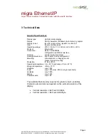
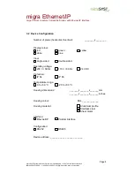
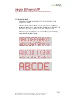
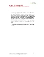
background image


microSYST Systemelectronic GmbH, Am Gewerbepark 11, 92670 Windischeschenbach 

 +49 9681 91960-0, 

 +49 9681 91960-10, info@microsyst.de, www.microsyst.de 


migra Ethernet/IP


Large Format, Graphics Compatible Display with Ethernet/IP Interface


User’s Manual 


Summary of Contents for migra Ethernet/IP

Page 1: ...tronic GmbH Am Gewerbepark 11 92670 Windischeschenbach 49 9681 91960 0 49 9681 91960 10 info microsyst de www microsyst de migra Ethernet IP Large Format Graphics Compatible Display with Ethernet IP Interface User s Manual ...

Page 2: ...a Unit 17 3 8 3 Trail 17 3 9 Displays with a Vertical Resolution 64 Pixels 18 3 10 Description of the Data Unit for Online Frames 19 3 10 1 Online Texts 20 3 10 1 1 Selecting a Character Set 20 3 10 1 2 Positioning the Cursor 21 3 10 1 3 Configuring Attributes 21 3 10 2 Texts Graphics and Variables 22 3 10 2 1 Querying Text 22 3 10 2 2 Adjusting Speed for Moving Screen Texts 22 3 10 2 3 Querying G...

Page 3: ...4 2 Adjusting Brightness 32 3 10 5 Digital Inputs and Outputs 33 3 10 6 Macros 34 3 10 6 1 Start Macro Execution 34 3 10 6 2 Input dependent Macro Jump 35 3 10 6 3 Pause during Macro Execution 37 3 10 6 4 Stop Macro Execution 37 3 11 Response Frames 38 3 12 Multiple ESC Sequences 39 3 13 Examples 40 3 14 Parallel Interface 41 3 14 1 Timing at the Parallels Inputs 41 3 14 2 Input Level at the Paral...

Page 4: ...sign allows for cost effective variants of various size as well as different character heights and numbers of digits Especially important information can be colour highlighted with the multicolour model MC Functions Data transmission Ethernet IP interface Configuration with PC software Text different font sizes and types and graphics can both be displayed Standard font flashing font moving screen ...

Page 5: ...temelectronic GmbH Am Gewerbepark 11 92670 Windischeschenbach 49 9681 91960 0 49 9681 91960 10 info microsyst de www microsyst de 2 Application Example Schematic diagram of the display unit at the interface SPS Control PC Configuration Ethernet IP Interface Display Controlling Display Unit migra Ethernet IP ...

Page 6: ...or 24 VDC 20 Protocol Ethernet IP Connection RJ45 10 100 MBit s configuration via RS232 interface Housing powder coated aluminium Housing dimensions see chapter device configuration Mounting articulated arm or hanging mount bracket for wall mounting Protection IP 54 or IP 65 Operating temperature 0 to 50 C optionally 20 to 50 C Storage temperature 25 to 70 C Graphics max 1000 Texts max 1000 max 25...

Page 7: ...the power supply When disconnecting the power supply the following sequence has to be observed o Disconnect the power supply cable from the power supply o Disconnect the power supply cable from the display Be sure to use a valid colour when creating texts Example Green lettering may not be used with a red single colour display no display appears in this case When selecting X and Y coordinates for ...

Page 8: ...vertical ________x________ Display colour red green yellow white blue View single sided double sided Operating voltage 230 V 50 Hz 110 V 60 Hz 24 V DC Protection IP 54 IP 65 Temperature range 0 to 50 C 20 to 50 C Housing dimensions _______x_______x_______mm _______x_______x_______inches Housing colour RAL _____________ Housing material Aluminium profile Stainless steel Sheet metal Interface Ethern...

Page 9: ...crosyst de 3 3 Display Elements Alphanumeric display modules with 16 x 16 64 x 8 or 64 x 16 dot matrices are utilized Attention As far as the software is concerned there is no difference between modules with 16 pixel lines and modules with 8 pixel lines The last 8 lines are simply not visible at a module with 8 pixel lines The following example depicts a module with 64 x 16 pixels including three ...

Page 10: ...y is not illuminated and if the integrated function LED blinks slowly i e 1 Hz the device is in the boot mode This indicates that the software or the configuration data currently stored to the integrated flash memory are incomplete This may result from a previously interrupted download operation If this is the case downloading must be repeated with the help of included PC software After power up t...

Page 11: ...er www anybus com in the area SUPPORT Anybus Communicator Ethernet Serial Gateway Connect the display with a RS232 null modem cable pins 2 3 3 2 5 5 to a PC Laptop Start the software Close the window Konfiguration auswählen with the button Cancel Press button Verbinden and after that button Upload Change only the marked fields according to your requirements Click button Download to transmit the co...

Page 12: ...e enclosed software micon 5 serves for the configuration of the display s variables and graphics Connect a PC Laptop via Ethernet with the display 1 1 cable if using a switch hub crosslink cable at direct connection Installation Execute the enclosed file setup exe in the path MICON of the enclosed CD and follow the instructions Start After the start the dialog Properties appears The IP address of ...

Page 13: ...croSYST Systemelectronic GmbH Am Gewerbepark 11 92670 Windischeschenbach 49 9681 91960 0 49 9681 91960 10 info microsyst de www microsyst de Select the folder migra Adjust the display modules depending on the display type One module smallest unit has 64x16 pixels resolution Click at the button OK ...

Page 14: ... Toggle byte The toggle byte must be increased by 1 if the frame shall be processed However the toggle byte must only be changed if the lock byte 0 see chapter General Frame Description Otherwise there is a lock from the configuration software MICON because it controls the display at the moment The lock byte is read from address 0x3FE of the display interface with explicit messaging The transmit b...

Page 15: ...frame byte has been received depending upon baud rate and HEX switch settings The pause between the individual frame bytes may not exceed this period of time The pause between the individual frames must exceed this period of time The next frame can be transmitted immediately after the response frame has been received If no response frame is used the MIGRA is not ready to receive a new frame until ...

Page 16: ...rnet interface is utilised SA Source Address normally set to 80H when an Ethernet interface is utilised FC Frame Control control for the communications sequence Bit 7 set permanently to 1 Bits 6 2 reserved 0 Bit 1 0 do not use checksum do not use LEN H L CHK H L 1 use checksum use LEN H L CHK H L Bit 0 0 do not send response 1 send response LEN H High nibble length number of high nibble data bytes...

Page 17: ...ommands 3 8 3 Trail If bit 1 is not set in the FC byte no checksum ETX End of Text 00000011B End of Text 03H If bit 1 is set in the FC byte use checksum CHK H CHK L ETX High nibble from sum of all previous bytes without STX Low nibble from sum of all previous bytes without STX End of Text 1111XXXXB 1111XXXXB 00000011B Checksum low byte for sum of DA SA FC LEN H LEN L and all data bytes CHK H High ...

Page 18: ...l the large format display 1 The controller boards of the large format display are accessed separately with two different addresses Bit 0 of the Byte FC must be set see chapter Header Example Querying graphics Transmit frame 02 81 80 81 1B 47 2B 30 30 30 03 Wait for response 02 80 81 80 30 03 Transmit frame 02 82 80 81 1B 47 2B 30 30 30 03 Wait for response 02 80 82 80 30 03 2 The large format dis...

Page 19: ...y unit All variables graphics and texts are written to the display starting at the selected X and Y coordinates and then proceed down and to the right The display s physical limits may not be exceeded during this process otherwise no display appears Note Text variable graphic character set and bar graph indices in the PC software and at the controlling are 0 based Frames which contain no online te...

Page 20: ...of ASCII code 0AH or 0DH by transmitting the escape sequence for setting cursor position ESC C If the display limits are exceeded read out is continued at the next line or at the first line of the display unit 3 10 1 1 Selecting a Character Set Byte 1 Byte 2 Byte 3 Byte 4 ESC Function Character set no tens Character set no ones 1Bh Z normal character width z uniform character width 0 9 0 9 Three c...

Page 21: ...sitioning the Cursor Byte 1 Byte 2 Byte 3 Byte 4 Byte 5 Byte 6 Byte 7 Byte 8 ESC Function X Position hundreds X Position tens X Position ones Y Position hundreds Y Position tens Y Position ones 1Bh C 0 9 0 9 0 9 0 9 0 9 0 9 3 10 1 3 Configuring Attributes Byte 1 Byte 2 Byte 3 Byte 4 Byte 5 ESC Function Foreground colour Background colour Blinking 1Bh A 0 black 1 green 2 red 3 yellow 0 black 1 gree...

Page 22: ...lack is used if the background colour has been set to transparent 3 10 2 2 Adjusting Speed for Moving Screen Texts Byte 1 Byte 2 Byte 3 ESC Function Moving Screen Speed 1Bh L 0 static 1 1 8 seconds 9 0 2 seconds All moving screen texts are set into motion at the selected speed The default setting is 9 0 2 seconds per step and this setting is always activated each time the device is switched on 3 1...

Page 23: ... Byte 1 Byte 2 Byte 3 Byte 4 Byte 5 Byte 6 Byte 7 133 ESC Function Set Variable no hundreds Variable no tens Variable no ones Variable values 1Bh V set 0 9 0 9 0 9 20h FFh Variables may include up to 127 characters the length of the variables is set during configuration The same number of characters is overwritten in the variable as is transmitted with the frame In order to avoid flickering the ol...

Page 24: ...ead out The background colour used with the variables may not be transparent and a character set with uniform character width should be used in order to assure correct display Otherwise the variable must be cleared prior to changing and then displayed once again Variable content is stored to RAM only After the device has been switched off and back on again the variables are returned to their pre c...

Page 25: ...face at which the bar graph is displayed is overwritten with the current online background colour from the last ESC A frame Black is used if the background colour has been set to transparent If a variable is linked to the bar graph it is cleared from the display as well Up to 255 bar graphs are possible numbers 0 through 254 The maximum variable length for linked variables is 127 characters 3 10 2...

Page 26: ...lue selected in the configuration The end of the bar graph is determined by the transmitted value The bar graph is displayed in the selected colour at the reference value position If the bar graph exceeds any of the colour limits measured from the reference point it is displayed in the colour selected for the respective colour limit as of this point Four colour limits can be defined Each colour li...

Page 27: ...he new value starting at the right If a variable is preset to preceding zeros are suppressed i e replaced with blanks If a variable is preset to preceding zeros are displayed If a digit is occupied by the dollar sign it is overwritten with the new preceding plus or minus sign Example Variable preset m s Value 9 00009 Display 0 9 m s If minimum or maximum values are violated the current values blin...

Page 28: ...l Point Byte 1 Byte 2 Byte 3 Byte 4 Byte 5 Byte 6 Byte 7 Byte 8 Byte 9 ESC Function Colour X pos hundreds X pos tens X pos ones Y pos hundreds Y pos tens Y pos ones 1Bh P 0 black 1 green 2 red 3 yellow 0 9 0 9 0 9 0 9 0 9 0 9 3 10 3 3 Reading Out the Decimal Point from the Display Query Byte 1 Byte 2 Byte 3 Byte 4 Byte 5 Byte 6 Byte 7 Byte 8 Byte 9 ESC Function Query code X pos hundreds X pos tens...

Page 29: ...red 3 yellow 0 black 1 green 2 red 3 yellow T transparent Upper Left Hand Corner Position Byte 5 Byte 6 Byte 7 Byte 8 Byte 9 Byte 10 X position hundreds X position tens X position ones Y position hundreds Y position tens Y position ones 0 9 0 9 0 9 0 9 0 9 0 9 Lower Right Hand Corner Position Byte 11 Byte 12 Byte 13 Byte 14 Byte 15 Byte 16 X position hundreds X position tens X position ones Y posi...

Page 30: ...yte 7 Byte 8 Byte 9 ESC Function Direction Speed Increment Start line tens Start line ones End line tens End line ones 1Bh S 0 off 1 up 2 down 0 static 1 1 8 sec 9 0 2 sec 1 1 pixel 9 9 pixels 0 no scrolling 0 9 0 9 0 9 0 9 Scrolls once through a portion of the screen from the start line to the end line speed static or cyclically in steps with a value ranging from 1 to 9 pixels The Y positions of ...

Page 31: ...tatic 1 1 8 sec 9 0 2 sec 1 1 pixel 9 9 pixels 0 no scrolling 0 9 0 9 0 9 0 9 0 9 0 9 Scrolls once through a portion of the screen from the start line to the end line speed static or cyclically in steps with a value ranging from 1 to 9 pixels The y position of the first and last pixel lines within the scrolling range define the start and end lines end line start line Only the last selected scrolli...

Page 32: ...nking period duration 1Bh B 0 2 seconds 9 0 2 seconds The selected blinking period duration applies to all blinking texts The default value 9 is activated each time the device is switched on 3 10 4 2 Adjusting Brightness Byte 1 Byte 2 Byte 3 Byte 4 Byte 5 Byte 6 ESC Function Colour Brightness hundreds Brightness tens Brightness ones 1Bh H 1 2 0 9 0 9 0 9 Within a range of 0 to 100 for each of the ...

Page 33: ...ts Large format display with a vertical resolution of more than 64 pixels can optionally be equipped with up to 16 digital inputs Request Frame Byte 1 Byte 2 Byte 3 Byte 2 n Byte 18 ESC Function Output bit 1 Output bit n Output bit 16 1Bh D 0 or 1 0 or 1 0 or 1 0 clear output 1 set output else retain previous output status Response FC byte bit 0 1 Byte 1 Byte 2 Byte 3 Byte 2 n Byte 18 ESC Function...

Page 34: ...hey are analogous to the data units in the online frames The first macro is executed after the device is switched on if one exists Subsequent macros are executed every 100 ms Macro execution is stopped after the last macro has been executed 3 10 6 1 Start Macro Execution Byte 1 Byte 2 Byte 3 Byte 4 Byte 5 ESC Function Macro no hundreds Macro no tens Macro no ones 1Bh M 0 9 0 9 0 9 Execution starts...

Page 35: ...Option B The macro execution is continued at the digit Macro no 000 999 if the indicated input was read in at least once with the status 0 or 1 since the last query with exactly this command The digital inputs are usually read in every 100 ms Byte 1 Byte 2 Byte 3 Byte 4 Byte 5 Byte 6 ESC Function Macro no hundreds Macro no tens Macro no ones E fixed 1Bh M 0 9 0 9 0 9 E Byte 7 Byte 8 Byte 9 No of q...

Page 36: ...d 1 000 ESC M005E0 1 2 001 ESC M007E1 1 3 002 ESC M009E2 1 4 003 ESC w010 5 004 ESC M000 6 005 ESC T 000 7 006 ESC M000 8 007 ESC T 001 9 008 ESC M000 10 009 ESC F0 11 010 ESC M000 The Inputs 0 to 2 are queryied every 1 second If Input 0 is set text 000 is displayed If Input 1 is set text 001 is displayed This also happens if the input was set only for a short time at least 100 ms for example duri...

Page 37: ...Byte 4 Byte 5 ESC Function Pause duration hundreds Pause duration tens Pause duration ones 1Bh w 0 9 0 9 0 9 Sets the time which elapses until the next macro is executed in steps of 100 ms A macro is normally executed every 100 ms until the last macro has been completed After the ESC w sequence macro execution is stopped for the specified pause duration This sequence can be used as part of a macro...

Page 38: ...it to the master STX DA SA FC Data Unit ETX Start of text Destination address Source address Frame control Error code End of text 00000010B 10000000B 10000001B 10000000 B 00000011B 2 128 129 128 0 5 3 Error Codes and their Meanings Value ASCII character Meaning 0 No error 1 Incorrect checksum 2 Reserved 3 Incorrect number of data bytes LEN H L invalid escape sequence 4 Element text variable graphi...

Page 39: ...he standard controlling and to the macro list The partition frames can be a ESC sequence or a online text each If a online text shall follow after the ESC sequence it must be separated with the separator sign 31D 1FH from the ESC sequence The separator itself is not evaluated The maximum length of the data unit of a complete frame is 230 characters Example Data unit 1BH Z01 1BH C002003 1BH A301 1F...

Page 40: ...000010B 10000001B 10000000B 10000001B 00000011B 2 129 128 129 3 Response from large format display unit if no errors occur STX DA SA FC Data Unit ETX Start of text Destination address Source address Frame control Error code End of text 00000010B 10000000B 10000001B 10000000B 00000011B 2 128 129 128 0 3 2 With checksum and response in short form The character A is to be displayed at the large forma...

Page 41: ...fo microsyst de www microsyst de 3 14 Parallel Interface Functions can be initialised via the 16 digital inputs which are analogous to the online frames used for the serial interface 3 14 1 Timing at the Parallels Inputs Data Bits 1 15 Strobe Valid Data 10 90 24V 24V 0V 0V Valid Data 110ms 110ms 110ms 3 14 2 Input Level at the Parallel Inputs Level Voltage Range U low 0 to 1 6 V DC U high 18 to 30...

Page 42: ...ach 49 9681 91960 0 49 9681 91960 10 info microsyst de www microsyst de 3 14 3 Querying Text 16 15 14 13 12 11 10 9 8 7 6 5 4 3 2 1 For example the following assignments are used to display text 12 16 15 14 13 12 11 10 9 8 7 6 5 4 3 2 1 1 0 0 1 0 0 0 0 0 0 0 0 1 1 0 0 Number 0 to 255 Strobe rising edge 0 to 1 apply value now Function text query 00 1 display 0 clear ...

Page 43: ...49 9681 91960 0 49 9681 91960 10 info microsyst de www microsyst de 3 14 4 Querying Graphics 16 15 14 13 12 11 10 9 8 7 6 5 4 3 2 1 For example the following assignments are used to clear graphic 7 16 15 14 13 12 11 10 9 8 7 6 5 4 3 2 1 1 0 1 0 0 0 0 0 0 0 0 0 0 1 1 1 Number 0 to 255 Strobe rising edge 0 to 1 apply value now Function query graphic 01 1 display 0 clear ...

Page 44: ... 12 11 10 9 8 7 6 5 4 3 2 1 Example The variable at the fourth digit is to be changed at a display with 6 variables Each digit is implemented by means of a variable numbers 0 through 5 In order to display a 9 at the fourth digit ASCII value 39H must be assigned to variable 3 fourth digit The inputs must be set up as follows to this end 16 15 14 13 12 11 10 9 8 7 6 5 4 3 2 1 1 1 0 0 0 0 1 1 0 0 1 1...

Page 45: ...roSYST Systemelectronic GmbH Am Gewerbepark 11 92670 Windischeschenbach 49 9681 91960 0 49 9681 91960 10 info microsyst de www microsyst de 3 14 6 Querying Macros 16 15 14 13 12 11 10 9 8 7 6 5 4 3 2 1 Number 0 to 255 Strobe rising flank 0 to 1 apply value now Function query macro 11 1 start 0 stop ...

Page 46: ...m Gewerbepark 11 92670 Windischeschenbach 49 9681 91960 0 49 9681 91960 10 info microsyst de www microsyst de 4 Connector Pin Assignments Ethernet Socket interface Note The two outer pins at the Ethernet socket are not used see above drawing for identification of pin 1 PIN Assignment 1 Tx 2 Tx 3 Rx 4 n c 5 n c 6 Rx 7 n c 8 n c ...

Page 47: ...lug 230 V AC 3 Pin Circular Plug 24 V DC Only with 24 V DC power supply 5 Pin Circular Plug only at displays with a maximum size of 4x4 display modules and optional digital outputs Relay 1 2 is controlled by digital output 1 2 frame ESC D PIN Assignment 1 L1 2 N PE PE PIN Assignment 1 GND 2 24 V DC 3 PE PIN Assignment 1 Relay 1 normally open a 2 Relay 1 normally open b 3 Relay 2 normally open a 4 ...

Page 48: ...eans of binary data at the position of the selected variable Query macro Starts stops macro execution at the selected macro Strobe If high level is applied to pin 16 110 ms the selected data are applied command is executed no later than 100 ms after occurrence of the rising edge except when the display unit has not yet completed processing of a previous command Please refer to chapter Parallel Int...

Page 49: ...er must not be set within normal operation If the display does not work according to the rules f e after a faulty software or configuration download the following steps should be executed Power off the display Set the boot jumper Power on the display Use the micon software to load the configuration resp the application software into the display again see corresponding chapter After a successful do...

Page 50: ...8 N 88 E 14 19200 8 O Light sensor test 94 F 15 19200 8 E off 3 30 ms maximum Switch S6 has no function Switches S1 and S2 specify the internal but not the Profibus address Standard test This test checks the connection between the controller and the displays A checkerboard must be shown if everything is all right Light sensor test For adjusting the light sensor of displays for outside use Shows th...

Page 51: ...960 0 49 9681 91960 10 info microsyst de www microsyst de LEDs Component Function Description LED 1 Power up Illuminated Normal operation Blinks at a frequency of approx 5 Hz Boot mode Blinks at a frequency of approx 1 Hz Defective software Blinks at a frequency of approx 0 5 Hz or irregularly LED 2 Power up Illuminated Communication Flickers during data transmission and receipt ...

Page 52: ... green device operational flashing green module has not been configured flashing red recoverable fault steady red internal error flashing green red self test LED 2 Network Status State Description steady off no power or no IP address steady green connection to SPS flashing green no connection to SPS flashing red connection timeout steady red duplicate IP address flashing green red self test LED 3 ...

Page 53: ...g green frame is received or transmitted LED 5 Subnet Status RS485 State Description steady off power off flashing green initializing and not running steady green running steady red stopped subnet error or timeout LED 6 Device Status State Description steady off power off flashing red green invalid or missing configuration steady green initializing flashing green running flashing red error code DI...

Page 54: ...00 8 xxxx1001 9 xxxx1010 A xxxx1011 B xxxx1100 C xxxx1101 D xxxx1110 E xxxx1111 F bin hex 0001 0010 0011 0100 0101 0110 0111 1000 1001 1010 1011 1100 1101 1110 1111 X 0 P p X 1 A Q a q ü ß X 2 B R b r X 3 C S c s X 4 D T d t ä ö X 6 F V f v X 5 E U e u X 7 G W g w X 8 H X h x X 9 I Y i y Ö X J Z j z Ü X K k X X L l X X M m X N n Ä X O _ o X X X X X X X X X X X X X X X X X X X X X ß X X X X X X X X...

Page 55: ...ired by direct illumination with bright light sources and or direct sunlight The display must be switched off before cleaning Protect the display from excessive humidity extreme vibration direct sunlight and extreme temperatures Non observance may lead to malfunctioning or destruction of the device Under certain circumstances electrical shock fire and explosion may occur as well Information concer...

Page 56: ...h confirm that the above mentioned product meets the requirements of the following standard Die Übereinstimmung des bezeichneten Produktes mit den Vorschriften der angewandten Richtlinie n wird nachgewiesen durch die Einhaltung folgender Normen Vorschriften The conformity of the product described above with the provisions of the applied Directive s is demonstrated by compliance with the following ...

Page 57: ...bservance of notification requirements is equated with acceptance of the defect Defects and their symptoms must be described as accurately as possible in order to allow for reproducibility and elimination The buyer must provide for access to all required and or useful information regarding defects at no charge as well as to the affected devices and must make all of the required data and machine ti...

Page 58: ... 5 5 Versions Overview Version Date Remark Description 1 00 1 10 1 20 1 30 1 40 1 50 1 60 6 9 2005 11 27 2005 8 16 2010 6 2 2014 3 13 2015 4 29 2016 11 16 2017 Kreuzer Document created Kreuzer Several ESC sequences in a row are possible Technical data updated Chapter Configuration of the Ethernet IP Interface changed SC MC removed description of controller board Declaration of conformity Change of...

Reviews: