background image

Auto Invision II

Visit our website at

www.MillerWelds.com

Processes

OM-196 188K

July 2003

Description

MIG (GMAW) Welding

Pulsed MIG (GMAW-P)

Flux Cored (FCAW) Welding

Automatic Welding

Automatic Welding Interface And
Arc Welding Power Source

Operating Instructions and

Programming Instructions for

Summary of Contents for Auto Invision II

Page 1: ...lerWelds com Processes OM 196 188K July 2003 Description MIG GMAW Welding Pulsed MIG GMAW P Flux Cored FCAW Welding Automatic Welding Automatic Welding Interface And Arc Welding Power Source Operating Instructions and Programming Instructions for ...

Page 2: ...alue established in 1929 This Owner s Manual is designed to help you get the most out of your Miller products Please take time to read the Safety precautions They will help you protect yourself against potential hazards on the worksite We ve made installation and operation quick and easy With Miller you can count on years of reliable service with proper maintenance And if for some reason the unit ...

Page 3: ...pheral Receptacle Functions 17 3 11 Touch Sensor Operation 18 3 12 Touch Sensor Board PC18 Switch S1 Settings 18 3 13 Connecting Setup Pendant To Welding Power Source 19 SECTION 4 OPERATION 20 4 1 Operational Terms 20 4 2 Lower Front Panel Controls 21 4 3 Meter Functions 21 4 4 Upper Front Panel Controls 22 4 5 Duty Cycle And Overheating 23 4 6 Volt Ampere Curves 23 4 7 Setup Pendant Controls 24 S...

Page 4: ...NG 88 9 1 Weld Cycle For Pulse Welding 88 9 2 Setting Preflow Sequence Display 88 9 3 Setting Weld Sequence Display 89 9 4 Setting Crater Sequence Display 89 9 5 Setting Postflow Sequence Display 90 SECTION 10 TEACHING A PULSE WELDING PROGRAM 90 10 1 Pulse Waveform Explained 90 10 2 Teach Points Explained 91 10 3 Selecting Teach Point Wire Feed Speed For Pulse Welding Program 92 10 4 Setting Teach...

Page 5: ...rc Start Volt Sense Error Shutdown 114 14 14 Selecting Program Name Feature 115 14 15 Remote Program Select 115 14 16 Remote Program Setting 115 14 17 Jog Wire Feed Speed Selection 116 14 18 Flow Selection 116 14 19 Arc Voltage Error Selection 117 14 20 Stick Check Selection 117 14 21 Setting Ramps Function 118 14 22 Software Version Number 118 14 23 Exiting The Setup Menu 118 SECTION 15 CONTROL M...

Page 6: ... 93 C 133 04 93 68 EEC Standards Electromagnetic compatibility EMC Product standard for arc welding equipment EN50199 December 1995 Arc Welding Equipment part 1 CEI IEC 60974 Degrees of Protection provided by Enclosures IP code IEC 529 1989 Draft IEC 60974 5 Arc Welding Equipment part 5 wire feeders JWG1 Sec 158 July 2000 Insulation coordination for equipment within low voltage systems Part 1 Prin...

Page 7: ...or that cord plug is connected to a properly grounded receptacle outlet D When making input connections attach proper grounding conduc tor first double check connections D Frequently inspect input power cord for damage or bare wiring replace cord immediately if damaged bare wiring can kill D Turn off all equipment when not in use D Do not use worn damaged undersized or poorly spliced cables D Do n...

Page 8: ... welding wire at contact tip when not in use D Wear oil free protective garments such as leather gloves heavy shirt cuffless trousers high shoes and a cap D Remove any combustibles such as a butane lighter or matches from your person before doing any welding FLYING METAL can injure eyes D Welding chipping wire brushing and grinding cause sparks and flying metal As welds cool they can throw off sla...

Page 9: ... maintained D Keep high frequency source doors and panels tightly shut keep spark gaps at correct setting and use grounding and shielding to minimize the possibility of interference ARC WELDING can cause interference D Electromagnetic energy can interfere with sensitive electronic equipment such as computers and computer driven equipment such as robots D Be sure all equipment in the welding area i...

Page 10: ... is a human health hazard However studies are still going forth and evidence continues to be examined Until the final conclusions of the research are reached you may wish to minimize your exposure to electromagnetic fields when welding or cutting To reduce magnetic fields in the workplace use the following procedures 1 Keep cables close together by twisting or taping them 2 Arrange cables to one s...

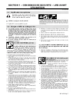
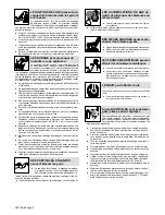
Page 11: ...tion est bien raccordé à la borne de terre du sectionneur ou que la fiche du cordon est raccordée à une prise correctement mise à la terre D En effectuant les raccordements d entrée fixer d abord le conducteur de mise à la terre approprié et contre vérifier les connexions D Vérifier fréquemment le cordon d alimentation pour voir s il n est pas endommagé ou dénudé remplacer le cordon immédiatement ...

Page 12: ...ct D Porter des vêtements de protection dépourvus d huile tels que des gants en cuir une chemise en matériau lourd des pantalons sans re vers des chaussures hautes et un couvre chef D Avant de souder retirer toute substance combustible de vos poches telles qu un allumeur au butane ou des allumettes DES PARTICULES VOLANTES peuvent blesser les yeux D Le soudage l écaillement le passage de la pièce à...

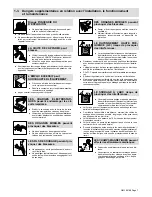
Page 13: ... dispositifs de protection LE RAYONNEMENT HAUTE FRÉ QUENCE H F risque de provoquer des interférences D Le rayonnement haute frequence peut provoquer des interférences avec les équipements de ra dio navigation et de communication les services de sécurité et les ordinateurs D Demander seulement à des personnes qualifiées familiarisées avec des équipements électroniques de faire fonctionner l install...

Page 14: ...nétiques basse fréquence Le courant de soudage pendant son passage dans les câbles de sou dage causera des champs électromagnétiques Il y a eu et il y a encore un certain souci à propos de tels champs Cependant après avoir ex aminé plus de 500 études qui ont été faites pendant une période de recherche de 17 ans un comité spécial ruban bleu du National Re search Council a conclu L accumulation de p...

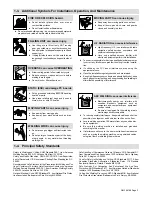
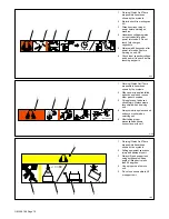
Page 15: ...2 Use forced ventilation or local exhaust to remove the fumes 2 3 Use ventilating fan to remove fumes 3 Welding sparks can cause explosion or fire 3 1 Keep flammables away from welding Do not weld near flammables 3 2 Welding sparks can cause fires Have a fire extinguisher nearby and have a watchperson ready to use it 3 3 Do not weld on drums or any closed containers 4 Arc rays can burn eyes and in...

Page 16: ...ng Watch Out There are possible hazards as shown by the symbols 2 When power is applied failed parts can explode or cause other parts to explode 3 Flying pieces of parts can cause injury Always wear a face shield when servicing unit 4 Always wear long sleeves and button your collar when servicing unit 5 After taking proper precautions as shown connect power to unit 4 96 1 2 3 4 5 S 179 309 A 60 1 ...

Page 17: ...tive On Off Inductance Protective Earth Ground Voltage Input 2 3 Manufacturer s Rating Label S 184 765 2 4 Harmonic Data HARMONIC DATA per IEC 61000 3 12 draft 2000 9 29 PRIMARY 400V 30 5A 60hz LOAD 450A 38Vdc 390IPM MAXIMUM OUTPUT GMAW R sce 227 28 THD PWHD 61 Amps 35 Amps Table 4 balanced three phase equipment ...

Page 18: ...andard 50 To 780 ipm 030 To 062 in 0 8 To 1 6 mm 95 31 21 6 19 4 Three Phase 100 Duty Cycle 565 A 43 Volts DC 60 Duty Cycle 10 38 50 To 780 ipm 1 3 To 19 8 mpm 030 To 062 in 0 8 To 1 6 mm 95 31 21 6 19 4 Phase 565 A 43 Volts DC 60 Duty Cycle 1 3 To 19 8 mpm 0 8 To 1 6 mm Wire feed speed ranges are for GMAW welding While pulse welding wire feed speed ranges may be more limited see Section 9 While i...

Page 19: ...Tipping 1 OR Y Special installation may be required where gasoline or volatile liquids are present see NEC Article 511 or CEC Section 20 801 915 B The proper interface kit must be installed in the interface unit to allow it to be connected to the robot 1 Robot Will Vary According To Application 2 Motor Drive Assembly 3 Gas Cylinder 4 Gas Hose 5 Robot Control 6 Robot Input Output Cable 7 Remote Pro...

Page 20: ...95 Ref 801 914 A 600 95 120 2 70 2 95 2 120 3 95 3 120 3 120 Weld cable size mm2 is based on either a 4 volts or less drop or a current density of at least 300 circular mils per ampere S 0007E 802 748 1 115 V 10 A AC Receptacle Power is shared between duplex receptacle and internal 14 socket receptacle 2 Circuit Breaker CB1 3 Circuit Breaker CB2 CB1 protects duplex receptacle and 115 volts ac port...

Page 21: ...Needed 5 16 in Input Filter Board L1 GND PE Y Always connect grounding conductor first Y Turn Off welding power source and check voltage on input capacitors ac cording to Section 5 3 before proceeding Check input voltage available at site Remove left side panel 1 Input And Grounding Conductors See Section 3 7 Install ring terminals of proper size onto input conductors for connection to input filte...

Page 22: ...r flow switch jog and n o relay contacts circuitry 5 Robot Control Receptacle Remote Program Select Connection To Robot Control To connect matching interconnect ing cord to one of the above receptacles align keyway insert plug and tighten threaded collar Connect remaining end of cord to matching receptacle on applicable equipment see Section 3 4 6 10 Socket Receptacle Wire Feed Shielding Gas Contr...

Page 23: ...ing coolant system is operational Signal F Circuit common Jog H Contact closure to circuit common advances welding wire at wire drive assembly 802 748 Jog J Contact closure to circuit common retracts welding wire at wire drive assembly K Contact closure to L energizes Touch Sensor circuitry Touch Sensor ON And Output Signal L Circuit common Touch Sensor ON And Output Signal M Part touched is selec...

Page 24: ...voltage sensing circuit closes and a 24 volts dc output signal is sent to the robot control indicating weldment detection Touch sensor dc voltage on the welding wire will vary from 60 to 150 volts dc depending on the welding power source As soon as touch sensor turns on DANGER SENSOR ON appears on the front panel display 3 12 Touch Sensor Board PC18 Switch S1 Settings 212 321 A 1 Touch Sensor Boar...

Page 25: ...ff welding power source and weld control 1 Welding Power Source 2 Interconnecting Cord 3 Setup Pendant To make connections align plug with receptacle insert plug and use thumb screws on receptacle to secure plug 1 2 3 Disconnect the setup pendant from the welding power source before welding ...

Page 26: ...ch include preflow run in weld crater burnback and postflow Setup Screen Terms Access Code NOTE The optional Data Card is required to activate this feature With code off access to the setup displays is not restricted With code on the operator must know and enter the access code to access or change any of the setup displays To use code press Parameter Select button to enter access code When the cor...

Page 27: ... shuts down if no arc voltage is sensed An error message is displayed When this feature is off wire feeds even when there is no arc voltage sensed Wire Feed Mode Allows the selection of inches per minute or meters per minute for wire feed speed This mode is also used to select motor type standard speed low speed or high speed 4 2 Lower Front Panel Controls 1 Power Switch The fan motor is thermosta...

Page 28: ... Reverse Push Button Retracts wire up into the gun 5 Gas Indicator LED LED lights when gas solenoid is energized 6 Purge Push Button Momentarily energizes gas solenoid to purge air from gun shielding gas line or to adjust shielding gas regulator 7 Contactor Indicator LED LED lights when welding power source contactor is energized 8 Main Display Shows system state active program error messages weld...

Page 29: ...rage or duty cycle before welding Y Exceeding duty cycle can damage unit and void war ranty Overheating 0 15 A V OR Reduce Duty Cycle Minutes duty1 4 95 181 560 Continuous Welding 100 Duty Cycle At 450 Amperes 60 Duty Cycle At 565 Amperes 6 Minutes Welding 4 Minutes Resting 4 6 Volt Ampere Curves va_curve1 4 95 181 562 Volt amperecurves show minimum and maximum voltage and amper age output capabil...

Page 30: ...th security feature on welding power source to allow decreasing weld parametervalues within the allowable range 3 Parameter Select Button Press button to move indicator in right window display and to make selections in setup screens 4 Mode Select Button Press button to move indicator in left window display 5 InterconnectingCable Receptacle 6 Parameter Display 7 Mode Display 8 Card Slot 802 815 2 1...

Page 31: ... Months Replace damagedor unreadable label Repair or replace cracked cables Replace cracked torch body Repair or replace cracked cables and cords 6 Months Clean and tighten weld terminals Blow out inside 5 2 Blowing Out Inside Of Unit Y Do not remove case when blowing out inside of unit To blow out unit direct airflow through front and back louvers as shown 801 914 ...

Page 32: ... 3 Voltmeter Measure the dc voltage across the screw terminals on PC2 as shown until voltage drops to near 0 zero volts Proceed with job inside unit Rein stall cover when finished Tools Needed 5 16 in Ref 801 914 Ref 801 917 Y Significant DC voltage can remain on capacitors af ter unit is Off Always check the voltage as shown to be sure the input capacitors have discharged be fore working on unit ...

Page 33: ...t has overheated The unit has shut down to allow the fan to cool it see Section 4 5 Operation will continue when the unit has cooled 6 Help 6 Display Indicates that the input voltage is too low and the unit has automaticallyshut down Operation will continue when the voltage is within 15 of the operating range If this display is shown have an electrician check the input voltage 7 Help 7 Display Ind...

Page 34: ...causing the interface unit to stop the weld cycle and wait for the robot to stop 8 Error Card Read Display The card reader is not working properly May be caused by a bad data card a bad data card reader a faulty microprocessor circuit board or a wiring problem 9 No Flow Detected No coolant is detected after preflow in the weld cycle Check coolant system and flow switch for proper operation 10 Grou...

Page 35: ...PC12 see illustration for board location Refer to Section 5 7 for information on diagnostic LED s Reinstall cover and left side panel after checking diagnostic LED s 191 842 1 5 6 Weld Interface Board PC12 Diagnostic LED s LED12 LED11 LED10 LED9 LED6 LED5 LED8 LED7 LED4 LED3 LED2 LED1 LED13 Top View ...

Page 36: ... source supply is present on weld interface board PC12 Off Indicates 15 volts dc power source supply is not present on weld interface board PC12 7 On Indicates 15 volts dc power source supply is present on weld interface board PC12 Off Indicates 15 volts dc power source supply is not present on weld interface board PC12 8 On Indicates 5 volts dc is present on weld interface board PC12 Off Indicate...

Page 37: ...r board location Refer to Section 5 9 for information on diagnostic LED s Reinstall top cover after checking diagnostic LED s 1 5 8 Customer Interface Board PC14 Diagnostic LED s LED1 LED6 LED3 LED2 LED4 LED5 Top View LED7 LED8 LED10 LED12 LED9 LED11 LED14 LED13 LED15 LED16 LED23 LED25 LED22 LED24 LED21 LED20 LED19 LED18 LED17 ...

Page 38: ... 10 Off Input signal Off for RPS C 11 On Input signal On for RPS B 11 Off Input signal Off for RPS B 12 On Indicates remote program A selected Off Indicates remote program A not selected 13 On Input signal On from peripheral for touch sensor Off Input signal Off from peripheral for no touch sensor 14 On Indicates automatic configuration Bit B is set 14 Off Indicates automatic configuration Bit B i...

Page 39: ...ripheral for shielding gas purge 25 Off Input signal Off from peripheral for no shielding gas purge 26 On Input signal On for touch sensor 26 Off Input signal Off for no touch sensor 1 Motor Board PC13 Diagnostic LED s are visible inside unit located on PC13 see illustration for board location Refer to Section 5 11 for information on diagnostic LED s Reinstall cover after checking diagnostic LED s...

Page 40: ...le fuses called PTCs protect encoder power supply If motor cable has a short circuit PTCs will go to high resistance to protect PC13 Do a pin to pin check for shorted conductors inside cable jacket and replace cable if necessary Check motor encoder and replace encoder if necessary 5 Blinks Motor was not operating at proper speed for over 2 seconds This fault results from monitoring amount of veloc...

Page 41: ...OM 196 188 Page 35 Notes ...

Page 42: ...OM 196 188 Page 36 SECTION 6 ELECTRICAL DIAGRAMS Figure 6 1 Circuit Diagram For Welding Power Source ...

Page 43: ...OM 196 188 Page 37 203 505 A ...

Page 44: ...OM 196 188 Page 38 Figure 6 2 Circuit Diagram For Control Board PC1 Part 1 of 3 ...

Page 45: ...OM 196 188 Page 39 203 311 1 of 3 ...

Page 46: ...OM 196 188 Page 40 Figure 6 3 Circuit Diagram For Control Board PC1 Part 2 of 3 ...

Page 47: ...OM 196 188 Page 41 203 311 2 of 3 ...

Page 48: ...OM 196 188 Page 42 Figure 6 4 Circuit Diagram For Control Board PC1 Part 3 of 3 ...

Page 49: ...OM 196 188 Page 43 203 311 3 of 3 ...

Page 50: ...OM 196 188 Page 44 Figure 6 5 Circuit Diagram For Function Meter Board PC3 ...

Page 51: ...OM 196 188 Page 45 190 696 ...

Page 52: ...OM 196 188 Page 46 184 183 Figure 6 6 Circuit Diagram For Interconnect Board PC2 188 015 Figure 6 7 Circuit Diagram For Gate Boards PC4 And PC5 ...

Page 53: ...OM 196 188 Page 47 Notes ...

Page 54: ...OM 196 188 Page 48 Figure 6 8 Circuit Diagram For Interface Module ...

Page 55: ...OM 196 188 Page 49 193 709 A ...

Page 56: ...OM 196 188 Page 50 Figure 6 9 Circuit Diagram For Microprocessor Board PC11 ...

Page 57: ...OM 196 188 Page 51 191 838 ...

Page 58: ...OM 196 188 Page 52 Figure 6 10 Circuit Diagram For Motor Board PC13 ...

Page 59: ...OM 196 188 Page 53 212 354 A ...

Page 60: ...OM 196 188 Page 54 Figure 6 11 Circuit Diagram For Switch Board PC15 182 996 ...

Page 61: ...OM 196 188 Page 55 200 739 Figure 6 12 Circuit Diagram For Junction Board PC16 ...

Page 62: ...OM 196 188 Page 56 Figure 6 13 Circuit Diagram For Interface Board PC12 Part 1 of 2 ...

Page 63: ...OM 196 188 Page 57 191 843 A Part 1 of 2 ...

Page 64: ...OM 196 188 Page 58 Figure 6 14 Circuit Diagram For Interface Board PC12 Part 2 of 2 ...

Page 65: ...OM 196 188 Page 59 191 843 A Part 2 of 2 ...

Page 66: ...OM 196 188 Page 60 Figure 6 15 Circuit Diagram For Customer Interface Board PC14 Part 1 of 3 ...

Page 67: ...OM 196 188 Page 61 Pensar 86147s03 Part 1 of 3 ...

Page 68: ...OM 196 188 Page 62 Figure 6 16 Circuit Diagram For Customer Interface Board PC14 Part 2 of 3 ...

Page 69: ...OM 196 188 Page 63 Pensar 86147s03 Part 2 of 3 ...

Page 70: ...OM 196 188 Page 64 Figure 6 17 Circuit Diagram For Customer Interface Board PC14 Part 3 of 3 ...

Page 71: ...OM 196 188 Page 65 Pensar 86147s03 Part 3 of 3 ...

Page 72: ...OM 196 188 Page 66 Figure 6 18 Circuit Diagram For Touch Sensor Board PC18 174 578 A ...

Page 73: ...OM 196 188 Page 67 200 739 A Figure 6 19 Circuit Diagram For Setup Pendant ...

Page 74: ...OM 196 188 Page 68 Figure 6 20 Circuit Diagram For Setup Pendant Centronix Junction Board PC3 200 739 ...

Page 75: ...OM 196 188 Page 69 191 531 Figure 6 21 Circuit Diagram For Power Distribution Board PC20 ...

Page 76: ...D 1 2 5 6 7 8 9 10 44 45 46 55 59 60 62 63 64 65 66 67 68 70 75 71 72 73 74 76 77 78 79 80 81 82 83 84 85 81 86 87 13 15 11 9 48 47 58 57 56 12 14 49 16 17 18 19 20 21 22 23 24 25 26 27 28 29 30 31 32 33 34 35 36 37 38 39 40 41 42 43 88 89 61 69 69 90 91 92 50 51 52 53 54 Figure 7 1 Complete Assembly ...

Page 77: ...lphanumeric 20 pin 1 21 PC15 182 998 CIRCUIT CARD ASSY switch board 1 22 193 716 PANEL center 1 23 PC20 191 533 CIRCUIT CARD ASSY power distribution 1 24 T11 193 706 TRANSFORMER control 1 25 PC16 201 387 CIRCUIT CARD ASSY junction board 1 26 PC12 191 841 CIRCUIT CARD ASSY interface board 1 27 097 132 STAND OFF No 6 32 x 375 28 28 PC11 202 005 CIRCUIT CARD ASSY micro board 1 29 PC14 203 665 CIRCUIT...

Page 78: ...TS 1 PLG12 115 093 HOUSING PLUG SOCKETS 1 63 176 844 CORE ferrite 2 64 180 103 COIL DI DT 2 65 182 654 GASKET DI DT rubber 1 66 180 271 BRACKET mtg choke 1 182 738 HOLDER DI DT coils 1 67 SR1 184 260 KIT diode power module 1 68 PM1 2 186 656 KIT transistor IGBT module 1 69 RT1 2 173 632 THERMISTOR NTC 30K ohm 2 70 179 930 HEAT SINK power module 1 71 204 165 HEAT SINK rect dual diode 1 72 R1 2 C9 1...

Page 79: ...om 1 186 529 WRAPPER 1 173 111 PANEL rear 1 185 963 NAMEPLATE 1 PC1 158 160 CIRCUIT CARD ASSY side display 1 PC2 156 623 CIRCUIT CARD ASSY data card 1 PC3 200 738 CIRCUIT CARD ASSY connector 1 186 530 CABLE ribbon 1 PB1 4 144 842 ACTUATOR switch 4 201 425 CABLE 6ft 1 604 804 SCREW 8 15 x 375 hexwhd pln stl pld sht met 9 072 785 SCREW 6 32 x 375 hexwhd slt stl pld slffmg 12 181 157 STAND OFF No 6 3...

Page 80: ...OM 196 188 Page 74 Notes ...

Page 81: ...Auto Invision II OM 196 188K July 2003 Programming Instructions for ...

Page 82: ...them for an application see Section 10 8 1 Pulse MIG Programs Program 1 2 3 4 5 6 Hardwire Selected 035 Steel Argon Oxy 045 Steel Argon Oxy 035 Steel Argon CO2 045 Steel Argon CO2 035 309 Argon CO2 045 Steel 309 Argon CO2 7 3 64 5356 Argon 8 035 SIB Argon Softwire Selected 045 Steel Argon Oxy 035 4043 Argon 045 Steel Argon CO2 1 16 4043 Argon Selecting hardwire or softwire is done during setup see...

Page 83: ...422 82 132 2 4 28 7 5 1 200 395 69 114 2 3 27 6 3 8 150 367 56 96 2 1 26 4 2 5 100 340 43 78 2 0 25 3 1 3 50 312 30 60 1 8 24 2 8 4 Program 2 1 0 mm Steel 040 80 20 Argon CO2 Wire Size Type 1 0 mm 040 Steel Gas Ar CO2 19 L min 40 CFH MPM IPM Apk Abk PPS PWms Vpk COMMENTS 17 9 705 471 90 206 2 3 38 4 17 8 700 470 90 205 2 3 38 4 16 5 650 460 87 196 2 3 38 2 15 2 600 450 85 188 2 3 38 0 14 0 550 440...

Page 84: ...74 120 2 4 34 1 5 1 200 420 64 100 2 3 33 4 3 8 150 405 53 80 2 1 32 6 2 5 100 390 43 60 1 9 31 8 1 3 50 375 32 40 1 7 31 0 8 6 Program 4 8 mm 316 030 98 2 Argon CO2 Wire Size Type 8 mm 030 316 Gas Ar CO2 19 L min 40 CFH MPM IPM Apk Abk PPS PWms Vpk COMMENTS 15 6 615 301 66 117 2 0 33 1 15 2 600 300 65 115 2 0 33 1 14 0 550 295 61 109 1 9 33 0 12 7 500 290 58 103 1 9 33 0 11 4 450 285 54 96 1 8 32...

Page 85: ... 5 7 225 320 48 89 1 8 30 1 4 7 185 310 41 78 1 7 29 0 3 8 150 300 35 67 1 7 28 0 2 8 110 290 29 56 1 6 27 0 8 8 Program 6 1 2 mm 316 045 98 2 Argon CO2 Wire Size Type 1 2 mm 045 316 Gas Ar CO2 19 L min 40 CFH MPM IPM Apk Abk PPS PWms Vpk COMMENTS 18 6 735 491 180 215 3 3 35 2 17 1 675 480 175 205 3 2 34 4 15 7 620 469 164 195 3 1 33 6 14 3 565 458 153 185 3 1 32 8 12 9 510 446 141 175 3 0 32 0 11...

Page 86: ...0 5 7 225 320 48 90 1 8 28 6 4 7 185 310 41 80 1 7 28 1 3 8 150 300 35 70 1 7 27 7 2 8 110 290 29 60 1 6 27 2 8 10 Program 8 1 2 mm 308L 045 98 2 Argon CO2 Wire Size Type 1 2 mm 045 308L Gas Ar CO2 19 L min 40 CFH MPM IPM Apk Abk PPS PWms Vpk COMMENTS 18 6 735 491 186 274 3 5 36 0 17 1 675 480 175 210 3 4 34 8 15 7 620 464 164 196 3 3 33 6 14 3 565 458 153 183 3 2 32 5 12 9 510 446 141 169 3 1 31 ...

Page 87: ...5 90 149 2 5 30 5 6 4 250 381 81 138 2 2 28 8 5 1 200 338 72 127 2 0 27 2 3 8 150 294 62 116 1 7 25 5 2 5 100 250 53 105 1 5 23 9 1 3 50 206 44 94 1 2 22 2 8 12 Program 2 1 4 mm Metal Core 052 95 5 Argon CO2 Wire Size Type 1 4 mm 052 Metal Core Gas Ar CO2 19 L min 40 CFH MPM IPM Apk Abk PPS PWms Vpk COMMENTS 18 1 715 562 194 206 3 8 34 0 17 8 700 560 190 206 3 7 33 9 16 5 650 551 175 208 3 5 33 7 ...

Page 88: ...9 91 135 2 0 25 5 5 1 200 258 68 115 1 8 24 9 3 8 150 256 44 95 1 5 24 2 2 5 100 255 20 74 1 3 23 6 8 14 Program 4 1 0 mm ER 4043 040 Argon Wire Size Type 1 0 mm 040 ER 4043 Gas Ar 19 L min 40 CFH MPM IPM Apk Abk PPS PWms Vpk COMMENTS 19 4 760 476 136 176 1 8 33 2 18 5 725 470 130 170 1 7 32 5 17 7 695 464 124 164 1 6 31 8 16 9 665 459 118 158 1 6 31 2 16 1 630 453 111 152 1 5 30 5 15 2 595 448 10...

Page 89: ...70 288 38 72 1 1 25 3 5 5 215 294 31 50 1 0 25 2 4 1 160 300 25 28 1 0 25 1 4 0 155 300 25 27 1 0 25 1 8 16 Program 6 1 2 mm ER 5356 045 Argon Wire Size Type 1 2 mm 045 ER 5356 Gas Ar 19 L min 40 CFH MPM IPM Apk Abk PPS PWms Vpk COMMENTS 19 4 760 378 149 254 2 8 25 3 18 5 725 374 144 245 2 7 25 3 17 7 695 370 139 236 2 6 25 3 16 9 665 366 135 278 2 5 25 3 16 1 630 362 130 219 2 4 25 3 15 2 595 358...

Page 90: ...8 150 298 28 51 1 3 28 9 3 2 125 289 26 44 1 2 28 2 2 5 100 280 25 37 1 1 27 6 1 9 75 271 24 30 1 0 26 9 8 18 Program 8 1 0 mm Steel 040 98 2 Argon Oxy Wire Size Type 1 0 mm 040 Steel Gas Ar Oxy 19 L min 40 CFH MPM IPM Apk Abk PPS PWms Vpk COMMENTS 17 9 705 451 90 201 2 4 33 7 17 8 700 450 90 200 2 4 33 6 16 5 650 440 90 192 2 4 32 8 15 2 600 430 90 185 2 4 32 0 14 0 550 420 90 177 2 3 31 1 12 7 5...

Page 91: ...Select Button 1 Mode Display 2 Mode Select Button Press Mode Select button to move indicator in left window display Go to Section 8 20 Ref 154 109 Process Sequence SharpArc Card Process Sequence SharpArc Card 1 2 Prg 1 Pulse 035 Steel Argon Oxy ...

Page 92: ...anged 3 Pulse Panel Parameter Select Button Press pulse panel parameter select button to move indicator in right win dow display 1 Process Sequence SharpArc Card Prg 1 Pulse 035 Steel Argon Oxy 2 3 Prg 1 Pulse 035 Steel Argon Oxy Pulse 035 Steel Argon Oxy Teach Off 8 20 Setup Pendant Parameter Select Button ...

Page 93: ...ase Button Press button to increase value that is underlined by the moving line 2 Decrease Button Press button to decrease value that is underlined by the moving line 1 2 Prg 1 Pulse 035 Steel Argon Oxy Prg 2 Pulse 045 Steel Argon Oxy Prg 3 Pulse 052 Steel Argon Oxy Prg 2 Pulse 045 Steel Argon Oxy 8 21 Setup Pendant Parameter Increase And Decrease Buttons Increase Decrease Increase ...

Page 94: ...etting Preflow Sequence Display 1 Mode Select Button When unit is turned On Process is the default mode at other times use mode select button to select Sequence 2 Parameter Select Button Use parameter select button to select parameters 3 Preflow Parameters Display Preflow can be adjusted from 0 9 9 seconds If value set is zero 0 there is no Preflow sequence Go to Section 9 3 3 Prflw 0 0 Sec Prflw ...

Page 95: ...ection 9 4 Setting Crater Sequence Display 1 Crater Parameters Display Parameter ranges are as follows Seconds 0 2 50 Sec If value set is zero 0 there is no Crater sequence Trim Arc Length 0 99 Wire Feed Speed 50 780 Inches Per Minute IPM Go to Section 9 5 1 Cratr 0 00 Sec 50 Trim 200 IPM Cratr 0 20 Sec 50 Trim 200 IPM Cratr 0 20 Sec 60 Trim 150 IPM Cratr 0 00 Sec 50 Trim 200 IPM Cratr 0 20 Sec 60...

Page 96: ...ng wire and forms a droplet The droplet is forced into the weld puddle 2 Abk Background Current Of 10 255 Amperes Abk is the low weld current Background current preheats welding wire and maintains the arc When background current is too low the arc is unstable and hard to maintain 3 PPS Pulses Per Second Of 20 400 PPS pulse rate and frequency Hz are used interchangeably A PPS or pulse rate of 60 Hz...

Page 97: ... are established an arc must be struck and main tained for at least 5 seconds in teach mode This allows the wire feeder to learn the arc voltage length associated with the taught pulse parameters To ensure a proper arc length reading electrode stick out must be carefully maintained An alternate method is to adjust the Vpk value then turn off Teach Mode and weld If welding is performed with Teach M...

Page 98: ...rease decrease buttons to select On 3 IPM Teach Point The parameters associated with this wire feed speed teach point can be modified The wire feed speed value itself cannot be changed from the set point To set or adjust teach point parame ters go to Section 10 4 3 1 Process Sequence SharpArc Card Prg 1 Pulse 035 Steel Argon Oxy Pulse 035 Steel Teach Off Teach On 400 IPM 28 1 Vpk 340 Apk Teach On ...

Page 99: ...customized programs Customized programs can be reverted back to factory set values through memory reset see Section 14 12 Process Sequence SharpArc Card 1 Prg 1 C Pulse 035 Steel Argon Oxy 3 Teach On 450 IPM 31 2 Vpk 343 Apk Teach On 450 IPM 28 1 Vpk 340 Apk Teach On 450 IPM 28 1 Vpk 340 Apk 2 4 6 10 4 Setting Teach Point Parameters For Pulse Welding Program Parameter Select Increase Decrease Or P...

Page 100: ... 94 Make copies of this chart for future use NOTE Program Wire Size Type Gas Program Name Card Gun Model Flowrate CFH IPM Apk Abk PPS PWms Vpk COMMENTS Preflow Sec Run In Trim IPM Sec Crater Trim IPM Sec Postflow Sec ...

Page 101: ... button to select Process 1 Process Sequence SharpArc Card Prg 1 MIG 035 Steel Argon Oxy Process Sequence SharpArc Card Prg 1 MIG 035 Steel Argon Oxy 10 5 Changing To Adaptive Pulse Welding Parameter Select Increase Decrease Mode Select SECTION 11 TEACHING A MIG WELDING PROGRAM Ref S 0271 11 1 Weld Cycle For Mig Welding Wire Speed Weld Start Start Power Start Speed Preflow Time Arc Strike Weld Spe...

Page 102: ...Oxy 1 Setup Pendant Display When unit is turned On Process is the default mode Use mode select button to select Sequence 2 Parameter Select Button Use parameter select button to select parameters 3 Preflow Parameters Display Preflow can be adjusted from 0 9 9 seconds If value set is zero 0 there is no Preflow sequence Go to Section 11 4 3 Preflow 0 0 Sec Preflow 1 2 Sec 2 Process Sequence SharpArc...

Page 103: ...Set Desired Voltage Set Desired Wire Feed Speed Increase Proceed to next Section Start 18 0 Volt 200 IPM 0 2 Sec Start 18 0 Volt 200 IPM 0 5 Sec 1 Weld Parameters Display Parameter ranges are as follows Inductance 0 99 Volts 10 0 38 0 Volts Wire Feed Speed 50 780 Inches Per Minute IPM Go to Section 11 6 Weld Induct 30 20 0 Volt 200 IPM Weld Induct 30 20 0 Volt 420 IPM 1 Weld Induct 20 18 0 Volt 20...

Page 104: ...ncrease Decrease Increase Proceed to next Section Parameter Select Parameter Select Set Desired Voltage Increase Decrease Parameter Select Set Desired Wire Feed Speed Increase Decrease 1 Retract Parameter Display Parameter range is as follows Seconds 0 1 00 seconds If value set is zero 0 there is no Burnback sequence IPM 50 780 1 3 19 8 mpm Speed is program dependent Go to Section 11 8 1 Rtrct 150...

Page 105: ...run in program level 1 Run in Parameters Display Runin can be turned On or Off Runin is a function of wire feed speed only This is the speed at which wire feeds until an arc is established IPM 25 780 0 6 19 8 mpm The voltage setting will be the same as Start sequence if time is set in that sequence otherwise this sequence will use the welding power source voltage setting 1 Runin ON 100 IPM Runin O...

Page 106: ...ay Control to adjust Arc setting SharpArc setting range is from 0 to 20 The factory default is set at zero 0 When Arc value is increased toward 20 the arc cone narrows and the weld puddle becomes less fluid Process Sequence SharpArc Card Prg 1 Pulse 035 Steel Argon Oxy 1 SharpArc 0 SharpArc 10 Process Sequence SharpArc Card SharpArc 0 Mode Select Increase Decrease Set Desired Value Parameter Selec...

Page 107: ...ard on the label Write the name of the piece of equipmentthe card is used with on the label 2 Data Card 3 Card Slot Insert card into slot To format card turn On power to the unit Select Card from menu Data card formats when unit enters Card mode Exit Card mode and turn Off power Ref 802 816 Ref 155 823 1 2 3 THIS SIDE UP 1 2 3 4 5 6 7 8 9 10 11 12 13 14 60 M Data Card 13 1 Installing Data Card ...

Page 108: ...t available program number is automaticallyassigned 3 Read Used to transfer program data from card to unit 4 Delete Used to delete program data from card 5 Done Used to exit card display 6 Moving Line Moving line is under value that can be changed Process Sequence SharpArc Card Press Below 1 Pulse 035 Steel Argon Oxy Press 1 6 Write Read Delete Done 2 3 4 5 13 2 Using The Data Card Parameter Selec...

Page 109: ...ocess Sequence SharpArc Card Press Below Write Read Delete Done 1 Pulse 035 Steel Argon Oxy Press Name No 035 Steel Argon Oxy Press Name Yes 5007992 Frame Press Write Done Prg 1 to Card Prg 1 Press 1 Pulse 035 Steel Argon Oxy Press Name Yes 035 Steel Argon Oxy Press Name Yes 035 Steel Argon Oxy Press Name Yes 5007992 Frame Press Write Done Prg1 to Card Prg1 Press 1 Pulse 5007992 Frame Press 1 2 3 ...

Page 110: ...se increase or decrease button to select feeder program number where the card pro gram goes Process Sequence SharpArc Card Press Below 1 Pulse 035 Steel Argon Oxy Press 1 2 3 Read Card to Feeder Prg 1 Press WARNING Prg1 Will Be Lost Lose Yes Press Prg1 Will Be Lost Lose No Press Read Done Card Prg1 to Prg 1 Press 1 Pulse 035 Steel Argon Oxy Press 1 Pulse 035 Steel Argon Oxy Press Write Read Delete...

Page 111: ...elect button to select Card 1 Card Display 2 Moving Line Moving line is under value that can be changed 3 Delete Display Select program number to be deleted from card Process Sequence SharpArc Card Press Below WARNING Delete Card Prg2 Lose Yes Press Delete Card Prg2 Lose No Press Card Prg2 Deleted Press 2 MIG Press 3 MIG Press 1 2 3 2 MIG Press Write Read Delete Done 13 6 Deleting Programs From Ca...

Page 112: ...am number 1 through 8 to be locked 3 Program Lock Display When lock is off a program the operator can change all weld parameters of that program without restriction With lock on a program the operator cannot change parameters of that program Prog 2 Lock Off Prog 1 Lock Off Prog 2 Lock Off Prog 2 Lock On 1 2 3 Prog 2 Lock On Prog 3 Lock Off Press Mode Select Increase Parameter Select Increase Acces...

Page 113: ...o Reset Reset 1 Display Selections 2 Features 3 Settings To set up features that customize operation use the setup displays Features that can be customized are as follows Access Mig Type Aux Out Voltage Volt Min 10 0 Volt 1 Display Features Settings Default Section Selection Name Card Off On On 14 14 Programs Wire Feed Display IPM MPM IPM 14 9 Motor Type Standard Standard Low Speed High Speed Pres...

Page 114: ...ollow this procedure any time access is required Once in the set up displays use the Mode Select button to select a particular display To save any or all of the changes made while in the setup displays and or to exit the setup displays turn power to the unit Off and back On 14 2 Using Setup Displays 1 2 Access Mig Type Aux Out Voltage Volt Min 10 0 Volt 3 S e t u p 4 Mode Select Parameter Select F...

Page 115: ...he pulse panel Mode and Parameter Select buttons Press Parameter Select button to enter access code When the correct letter is entered the indicator automatically moves to the next character When the final access code letter is entered the display automatically changes to the initial setup display 1 Access Mig Type Aux Out Voltage Code Off Code On AAA Code On AAA Press Code On ZWX Press Enter Acce...

Page 116: ...eder is op erating On during the welding arc until arc goes out On during the entire weld cycle Off or never On 1 Access Mig Type Aux Out Voltage Aux Turn On w Feeder 14 5 Selecting Auxiliary Output Access Setup Display Press Mode Select Increase Increase Aux Turn On w Arc Aux Turn On w Weld Cyc Increase Aux Turn On Never 1 Voltage Feedback Display The Internal setting allows the unit to obtain vo...

Page 117: ...the Soft Start mode for 035 in 9 mm or smaller wire Low wire feed speeds may also require the Soft Start mode Arc start is at 75 of maximum amperage for pulse welding and once an arc is established welding is performed at set parameter values 1 Aux Output Voltage ArcStart Arc Time Pulse ArcStart Standard ArcStart Type SoftStart Press Mode Select Increase Access Setup Display 2 3 1 Arc Time Display...

Page 118: ...r High Speed ArcStart Arc Time Wirefeed Wiretype Display IPM Motor Type Standard Display MPM Motor Type Standard 1 Display IPM Motor Type Standard Display IPM Motor Type Low Spd Display IPM Motor Type High Spd 14 9 Selecting Units For Wire Feed Speed And Motor Type Press Mode Select Parameter Select Increase Access Setup Display Increase Decrease Increase ...

Page 119: ...Now 1 Arc Time Wire feed Wiretype Display Wire Type Softwire System Reset Now Press Mode Select Increase Access Setup Display After using system reset to store wire type selection into memory all other setup parameters return to factory default settings See Section 14 2 for procedure to return to setup displays and reset parameters 1 Display Select Display The display can show amps actual reading ...

Page 120: ...d setup including System and Arc Time If setup card is in card slot program will be loaded from card 5 Reset Default Displays Wiretype Display Memory Shutdown No Reset Program 1 Reset Press Process Sequence SharpArc Card Prg 1 Pulse 035 Steel Argon Oxy 1 2 5 System Reset Press 3 14 12 Resetting Memory Press Mode Select Parameter Select Increase Decrease Parameter Select Increase Decrease Access Se...

Page 121: ...on 14 16 When Off program selection must be done from Setup Pendant Shutdown Name Program Jog IPM Remote Select Off Remote Select On 1 Press Mode Select Increase Access Setup Display 14 16 Remote Program Setting When Remote Program Select is On program selection will be determined by remote input once a weld is intiated In Standby mode program selection can be done in a normal manner from the Setu...

Page 122: ...ow Robot Jog Remote Local Jog 200 ipm 1 14 17 Jog Wire Feed Speed Selection Press Mode Select Increase Access Setup Display Robot Jog local Local Jog 200 ipm Parameter Select Robot Jog local Local Jog 200 ipm Increase Decrease Robot Jog local Local Jog 425 ipm Parameter Select 1 Flow Display Provides a means to enable disable the flow switch input When this feature is off no monitoringis done for ...

Page 123: ...ions outside of the defined range for a period of time exceed ing the defined acceptable time pe riod cause either the error relay to energize or the unit to shut down depending on the Arc Start Volt Sense shutdown error setting Jog IPM Flow Monitor Stick Arc Volts On 2 0 Volts 1 0 Sec Arc Volts Off 1 When a system reset is done Monitor is set to Off 14 19 Arc Voltage Error Selection Press Mode Se...

Page 124: ...f 1 2 3 Prog 2 Start On Crater Off Prog 2 Start On Crater On Press Mode Select Increase Parameter Select Increase Access Setup Display Parameter Select Increase Monitor Stick Ramps Exit 4 1 Example Version Number Display When talking with service personnel this number may be required Check actual unit display for number The factory keeps this number on file with the serial num ber of the unit 1 St...

Page 125: ...ntrol setting 2 Setup Pendant Increase And Decrease Buttons 3 Power Switch On Front Panel Press and hold down both buttons while turning On unit Release buttons when Control appears on the front panel display 4 Setup Pendant Control Display Follow this procedure any time access is required To save any changes made while in the control display and or to exit the control display cycle power off and ...

Page 126: ...play Increase Decrease Process Sequence SharpArc Card Prg 1 Pulse 035 Steel Argon Oxy Rise Time Adaptive AutoConfig Retract A ms 800 Mode Select Go To Section 15 4 Or Power Switch A ms 680 15 3 Setting Adaptive Parameters 1 Adaptive Parameter Display Settings allow user to choose be tween two adaptive programs A or B Use Increase or Decrease button to change setting Press Mode Select button to go ...

Page 127: ... Select button to go to next parameter or cycle power off and back on at power switch to sav e setting and exit Control menu 1 Off Arc On No Analog Inputs Access Control Display Increase Decrease Process Sequence SharpArc Card Prg 1 Pulse 035 Steel Argon Oxy Rise Time Adaptive AutoConfig Retract On None Mode Select Go To Section 15 5 Or Power Switch Off Arc On Analog Inputs Increase Decrease Off P...

Page 128: ... Oxy Adaptive AutoConfig Retract ShrpStrt Retract On Mode Select Or Retract Off Go To Section 15 6 Power Switch Press Mode Select 15 6 Setting Sharp Start On Off 1 Sharp Start Display Settings allow user to turn the sharp start feature On or Off Sharp start should normally be left On The ability to turn sharp start Off is provided in case the user experiences problems with weld ends using flux cor...

Page 129: ... Page 123 1 Exit Control Menu Display Allows the user to leave the control menu 1 AutoConfig Retract ShrpStrt Exit Exit Cntrl Menu Now Press 15 7 Exiting The Control Menu Access Control Display Press Mode Select ...

Page 130: ......

Page 131: ...e Controls Accessory Kits Replacement Parts No labor Spoolmate Spoolguns Canvas Covers Miller s True Blue Limited Warranty shall not apply to 1 Consumable components such as contact tips cutting nozzles contactors brushes slip rings relays or parts that fail due to normal wear Exception brushes slip rings and relays are covered on Bobcat Trailblazer and Legend models 2 Items furnished by Miller bu...

Page 132: ... complete and retain with your personal records Always provide Model Name and Serial Style Number Call 1 800 4 A Miller or see our website at www MillerWelds com to locate a DISTRIBUTOR or SERVICE AGENCY near you Welding Supplies and Consumables Options and Accessories Personal Safety Equipment Service and Repair Replacement Parts Training Schools Videos Books Technical Manuals Servicing Informati...

Reviews: