background image


ZS3 Diagnostic Ultrasound System 
Service Manual 


Summary of Contents for Zonare ZS3

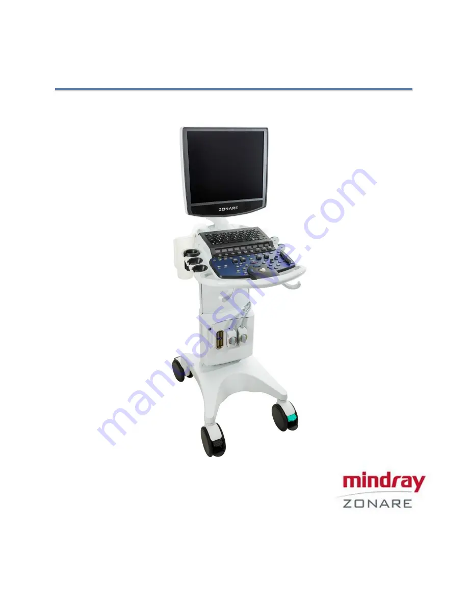
Page 1: ...ZS3 Diagnostic Ultrasound System Service Manual ...

Page 2: ...owing patents 6 251 073 6 569 102 6 618 206 6 663 567 6 685 645 6 733 455 6 773 399 6 866 631 6 866 632 6 896 658 6 936 008 6 980 419 6 997 876 7 022 075 7 087 020 7 226 416 7 238 157 7 352 570 7 361 145 7 510 529 7 627 386 7 382 309 7 699 781 8 002 705 8 226 561 D461 814 D462 446 D467 002 D469 539 D469 877 SHENZHEN MINDRAY BIO MEDICAL ELECTRONICS CO LTD Mindray Building Keji 12th Road South High ...

Page 3: ...isplay 26 Battery Pack Specifications 27 Standards and Compliance 32 4 System Overview 34 Major System Assemblies 34 User Interface Overview 35 Keyboard Functions 38 On Screen Dashboard System Status ICONs 41 Accessory Components 43 Rear I O Panel 44 5 System Uncrating Installation Procedures 45 Product Shipment 45 Electrical Requirements 45 Environmental and Space Requirements 45 Uncrating 45 Mec...

Page 4: ...ege Management 62 LDAP Privilege Management 68 User Field Name 70 Enable Barcode Login 70 Enable Encryption 71 8 Patient Information Management 72 Patient Information 72 New Patient Information 73 Retrieve Patient Information 78 9 DICOM HL7 84 DICOM Preset 85 Service Preset 87 DICOM Verifying 101 DICOM Services 102 DICOM Media Storage 108 10 Peripheral 110 Print Service 110 Barcode Reader Configur...

Page 5: ...Backup Operations 151 Restore Operations 152 Software Upgrade Installation 155 Installing System Software 156 Clean Software Install Procedure 159 Mindray Zonare FTP Site 160 Diagnostic Panel Operations 161 16 Care and Maintenance 170 Overview 170 Basic System Care 171 Transducer Maintenance 174 Check 174 17 Preventative Maintenance Forms 185 18 System Troubleshooting 189 Diagnostics 190 Troublesh...

Page 6: ...5 Power Module Removal Replacement 239 User Interface Removal Replacement 244 OLED Assembly UI Assy Removal Replacement 250 Dock Module Removal Replacement 255 Gas Spring Removal Replacement 259 20 Parts Catalog 263 System 264 Display 264 Accessories 266 User Interface 269 Module Cart Electronics 270 Internal Cabling 271 Power Module 272 Miscellaneous Cart Items 273 Peripherals 273 Options and Upg...

Page 7: ...ina E mail Address service mindray com Web site www mindray com Tel 86 755 81888998 Fax 86 755 26582680 United States and Canada Toll free live voice support 1 877 913 9663 Live technical support not toll free 1 650 316 3199 Technical support by email techsupport mindray com Sales support live voice 1 877 966 2731 ext 3 Sales support by email salessupport mindray com Web site www mindraynorthameri...

Page 8: ...tains the software driven imaging electronics and user interfaces keyboard monitor handles etc It houses the microprocessor memory amplifiers and power supplies for the microprocessor It sends electrical currents to and receives electrical pulses from the compatible transducers The Cart performs the calculations involved in processing the data to produce the displayed ultrasound images The ZS3 Car...

Page 9: ...it LCD Liquid Crystal Display LED Light Emitting Diode M M Mode Motion Mode Tissue NTSC National Television Standards Committee video standard PAL Phase Alternation by Line video standard PRF Pulse Repetition Frequency PW Pulsed Wave Mode Doppler Retrospective Post processing performed on frozen images from memory DGC Depth Gain Compensation USB Universal Serial Bus ...

Page 10: ...tient applied part C cardiac F floating applied part Alternating current AC Direct current DC Date of manufacture Manufacturer Caution ESD sensitive Recyclable material V Voltage Hz Cycles per second Waste Electrical Electronic Equipment Standard Applies to EU Member States only this system should not be treated as household waste Mindray meets the WEEE Standard For more information on returning o...

Page 11: ...ry Shipping Storage Temperature limits Shipping Storage This side UP Shipping Storage Do not stack above this container Shipping Storage Humidity limits Shipping Storage Pressure limits Federal law restricts this device to sale by or on the order of a licensed healthcare practitioner USA Protected against water immersion Immersion for 30 minutes at a depth of 1 meter ...

Page 12: ...for the system Before installation the users should Acquire the needed material Prepare for the delivery of the system Pay costs incurred for the modifications that are excluded from the sales list Note This equipment must be operated by skilled trained clinical professionals Before delivering the system ensure that the operating site is clean Do not put the system on a carpet that might attract d...

Page 13: ...see applicability of each of these noted WARNINGs during the course of the servicing process be prepared to avoid harm to persons and equipment by proper adherence It is not possible to anticipate every condition and situation in which ultrasound system will be used The following warnings and cautions represent typical situations that require special attention User knowledge and experience with a ...

Page 14: ...wer outlet or power cord integrity do not proceed Obtain qualified assistance To maintain proper grounding reliability use only Mindray Zonare recommended peripherals and accessories Use of non specified peripherals and accessories could result in risk of electrical shock or injury The ultrasound systems represent a potential explosion hazard if used in the presence of flammable anesthetics The sy...

Page 15: ...cer become cross contaminated The transducer must be removed from patient contact before application of a high voltage defibrillation The system is not intended for use in conjunction with high frequency HF surgical equipment tissue ablation devices Do not use transducers connected to the ultrasound system on patients while HF surgical devices are in use If using relevant standards compliant equip...

Page 16: ...t examination to prevent the possibility of a hazardous current path Warnings Ocular Imaging To avoid injury to the patient use only the Ocular Preset when imaging through the eye The FDA has established lower acoustic energy limits for ophthalmic use The system will not exceed these limits only if the Ocular Preset is selected Warnings Battery To avoid electrical shock do not touch the battery co...

Page 17: ...ection Be sure to check pins before connecting transducer to the Mindray Zonare ultrasound system If pins are bent broken or missing do not use the transducer and call Mindray Zonare Technical Support Immediately replace a transducer that exhibits any damage symptoms Before introducing the probe do not rub or spray the tip of the probe with an anesthetic agent Avoid forceful manipulations and exce...

Page 18: ...r message Be aware of the potential hazards associated with the environment where the ultrasound systems will be used The systems and or the external equipment can be damaged if signal levels are not appropriate If peripheral equipment not specifically authorized by Mindray Zonare is to be connected to the system it must meet all applicable electrical safety standards that apply to the system in o...

Page 19: ...ctrostatic discharge ESD or static shock is a naturally occurring phenomenon ESD is common in low humidity which can be caused by heating or air conditioning ESD shock occurs when electrical energy is discharged from one body to a differently charged body To lessen the occurrence of ESD use antistatic spray on carpets and flooring and antistatic mats To minimize potential ESD damage and electrical...

Page 20: ...mponent in a comprehensive diagnostic plan Never leave a probe in the disinfection solution for more than the specific time by the disinfection manufacturer Please refer to the instructions for use that came with the disinfectant for minimal required exposure times Do not forget to rinse the probe directly after disinfection Only use water soluble acoustic coupling gel Other coupling gels can caus...

Page 21: ...the case for transportation TEE transducer is a delicate medical instrument handle with care The multiplane TEE probe is a precision instrument which must be handled with care It may be damaged when dropped or abused In particular do not allow the ultrasonic window in the tip to come into contact with a sharp object Do not touch this window unnecessarily Never exert force onto the acoustic window ...

Page 22: ...tant for a high quality panoramic image Precautions 3D 4D Imaging 3D Measurements out of plane are potentially less accurate due to movement of tissue A good B Mode 2D image is important for a high quality 3D 4D image Precautions WIRELESS WIRELESS The Mindray Zonare Wireless option device is an RF Receiver and Transmitter operating using industry standard 802 11 b g protocols Use of the wireless o...

Page 23: ...ng Mindray Zonare ultrasound systems for human exams of any kind should thoroughly understand the implications of such use The American Institute of Ultrasound in Medicine AIUM has published a document titled Medical Ultrasound Safety AIUM 1994 ALARA is an abbreviation for the principle of prudent use of diagnostic ultrasound by obtaining the diagnostic information at a power output that is as low...

Page 24: ...ting Cooling requirements See power consumption above Air temperature 0 35 C 32 95F Humidity 15 80 noncondensing Pressure 700 1060 hPa Environmental storage Air temperature 20 60 C 4 140 F Humidity 15 90 noncondensing Pressure 500 1060 hPa Physical weight ZS3 system 91 5 kg without probes Power cord 0 6 kg 1 4 lbs USB printer bracket 3 4 kg 7 6 lbs Battery bracket 4 1 kg 9 1 lbs Operating weight s...

Page 25: ...M Modulation Technology DSSS CCK OFDM Modulation Type DBPSK DQPSK CCK BPSK QPSK 16QAM 64QAM Network Access Modes Infrastructure Ad Hoc Channels USA Canada 11 channels Europe 13 channels France 4 channels Japan 14 channels 13 channels for 802 11g Wireless Data Rate 802 11b 11 5 5 2 1 Mbps 802 11g 54 48 36 24 18 12 9 6 Mbps MAC CSMA CA with ACK RTS CTS Network Protocols TCP IP ARP ICMP DHCP DHS HTTP...

Page 26: ...ABDN ER DP551U Client Bridge ABDN ER DP551U NAT 3 Router Regulatory Approvals Worldwide Certificate Support FCC Part 15 Class B Sub C Modular Approval IOC CE ETSI EN300 328 ETSI 60950 1 ROHS and WEEE Compliant Display Parameter Value Display size 19 Resolution 1280 x 1024 Pixel pitch 0 41 mm Minimum contrast 10 1 Connectors Mini HDMI video mini DIN power Rotation Left Right 90 5 degree Advanced se...

Page 27: ...ications Type Parameter Value Electrical Power rating 15 6V 15Ah 234 Wh Chemistry NiMh Physical weight 4kg 10 lb Operational Operating time duration fully charged Up to 1 5 hours Physical dimensions Height 75 mm 3 in Width 260 mm 10 in Depth 355 mm 14 in ...

Page 28: ...d of View 67 degrees Radius of Curvature 33 mm Ultrasound Bandwidth 9 3 MHz 3 C9 3sp Penetration Depth 18 CM Number of Elements 128 Field of View 67 degrees Radius of Curvature 33 mm Ultrasound Bandwidth 9 3 MHz 4 C6 2 Penetration Depth 24 CM Number of Elements 128 Field of View 65 degrees Radius of Curvature 50 mm Ultrasound Bandwidth 6 2 MHz 5 C4 1 Penetration Depth 30 40 CM Number of Elements 6...

Page 29: ...192 Field of View 55 mm Ultrasound Bandwidth 14 5 MHz 8 L10 5 Penetration Depth 10 CM Number of Elements 128 Field of View 38 mm Ultrasound Bandwidth 10 5 MHz 9 L8 3 Penetration Depth 10 CM Number of Elements 128 Field of View 38 mm Ultrasound Bandwidth 8 3 MHz 10 E9 4 Penetration Depth 14 CM Number of Elements 128 Field of View 135 degrees Radius of Curvature 12 mm Ultrasound Bandwidth 9 4 MHz ...

Page 30: ...2 Ultrasound Frequency 5 0MHz Ultrasound Bandwidth n a 14 C8 3 3D Penetration Depth 24 CM Number of Elements 128 Field of View 79 77 degrees Ultrasound Bandwidth 8 3 MHz 15 E9 3 3D Penetration Depth 14 CM Number of Elements 128 Field of View 135 degrees Ultrasound Bandwidth 9 3 MHz 16 P8 3TEE Penetration Depth 18 CM Number of Elements 64 Ultrasound Bandwidth 8 3 MHz 17 L20 5 Penetration Depth 5 CM...

Page 31: ...CM Number of Elements 192 Field of View 54 degrees Radius of Curvature 41 mm Ultrasound Bandwidth 18 5 MHz 20 C6 1 Penetration Depth 27 CM Number of Elements 128 Field of View 70 degrees Radius of Curvature 62 mm Ultrasound Bandwidth 6 1 MHz 21 E9 3 Penetration Depth 14 CM Number of Elements 128 Field of View 138 degrees Radius of Curvature 12 mm Ultrasound Bandwidth 9 3 MHz ...

Page 32: ... monitoring equipment IEC 60601 1 2 2014 Certification Specification Compliance CISPR 11 RF emissions Group 1 Class A The ZS3 system is suitable for use in all establishments other than domestic and those directly connected to the public low voltage power supply network that supplies buildings used for domestic purposes IEC 61000 3 2 harmonic emissions Class A IEC 61000 3 3 voltage fluctuations fl...

Page 33: ...Immunity Compliance level 0 15MHz 80 MHz 3Vrms 2Hz IEC 61000 4 8 power frequency 50 60 Hz magnetic field immunity Compliance level 3A m 50 60Hz Electromagnetic environment guidance Power frequency magnetic fields should be at levels characteristic of a typical commercial or hospital environment IEC 61000 4 11 voltage dips short interruptions and voltage variations on power supply input lines Elect...

Page 34: ...ZS3 Service Manual Page 34 of 295 4 System Overview Major System Assemblies Figure 4 1 ZS3 System ...

Page 35: ...ZS3 Service Manual Page 35 of 295 User Interface Overview Figure 4 2 ZS3 Full Featured User Interface is shown above Figure 4 3 ZS3 Special Procedures User Interface is shown above ...

Page 36: ...e Press to enter Doppler mode Rotate to adjust gain 5 ZOOM Initiates the variable image magnification process 6 C mode Press to enter Color Doppler mode Rotate to adjust gain 7 B mode Press to enter B mode 2 D Rotate to adjust gain 8 Exam Type Brings up Exam Type Presets configuration menu and six user Preset setting to OLED display windows 9 Transduce r MTP Used to bring the available transducers...

Page 37: ...nd or AutoOpt DGC 17 Caliper Multi function key 1 Brings up dynamic caliper live or Calc menu frozen 2 Toggles on off the Auto Dop Trace function in PW Doppler mode 18 Calc Brings up the Calculations menu page 19 Pointer Brings up an arrow pointer which is used to 1 Operate the menu 2 Click on thumbnails 3 Click on soft mode switch control 4 Click on OLEDs to page 5 Click on System ICONS 20 Undo R...

Page 38: ...ts Changes gain of image at discrete depths 8 Sliders 25 Print Prints an image to a printer or stores an image or clip to media depending on configuration 26 Dual Mode Activates deactivates DUAL imaging mode 27 Annotation Press to display the Annotation softkeys for the selected exam preset and transducer 28 Protocol Used to enable controls for Stress Echo or Automatically Tutorial Workflow protoc...

Page 39: ...page of images in a multi image display format 6 DELETE This key only works when in in progress exam review or archived exam review When an image has been selected pressing the Delete key will tag the image for deletion by drawing a red X through it If the selected image already has been tagged for deletion red X pressing the Delete key will remove the red X untagging the image 7 FORMAT This key o...

Page 40: ...sition as the new Home position 17 ALT GR Alternate Graphics Used in conjunction with the QWERTY keyboard to enable access to international characters 18 TEXT Pressing Text will display the text annotation cursor Pressing Text again will remove the text annotation cursor 19 ARROW This is a toggle key It works when the image is live or frozen Pressing the key displays an arrow graphic in the middle...

Page 41: ...process approx 12 hours Battery Status Battery status is currently unknown Battery Status System running on Battery source power more than 25 remaining charge Battery Status System running on Battery source power 10 25 remaining charge Battery Status System running on Battery source power less than 10 remaining charge Removable Media USB Removable storage media USB is being initialized USB Local P...

Page 42: ...etwork disconnected Wireless Network Wireless Network transfer has an error Re Queuing of job etc preventing transfer Wireless Network Wireless signal strength 1 33 Wireless Network Wireless Network Wireless signal strength 34 66 Wireless Network Wireless Network Wireless signal strength 67 100 ...

Page 43: ...B memory stick into any available USB port 2 Make sure the stick is correctly oriented for the port When a USB memory stick is plugged in to a USB port a status icon is displayed on the bottom left of the imaging screen To Remove USB Memory Stick 1 Make sure the ZS3 system has fully completed downloading upgrades importing exporting or collecting log data to the USB memory stick before removing it...

Page 44: ...Rear I O Panel Figure 4 6 ZS3 Rear I O Panel FUNCTIONS I O CONNECTORS Function Direction 1 Ethernet 10 100BaseT Network Input Output 2 Serial Port eSATAp Input Output 3 USB Port Input Output 4 HDMI Connector video and audio Input Output ...

Page 45: ...systems configured for these power requirements are required for the ZS3 ultrasound system Environmental and Space Requirements The ZS3 ultrasound system may be located anywhere within the facility as long as there is appropriate power outlets and remote network connectivity at facilities utilizing a DICOM print storage device hook up Uncrating 1 Prior to opening any packaging inspect the shock wa...

Page 46: ...tion of the main cardboard shipping container and set aside Figure 5 2 ZS3 6 Remove the small boxes containing the transducers a maximum number of 4 and the small box containing accessories from the inner storage box area resting atop the ZS3 System Figure 5 3 ZS3 Banding strap ...

Page 47: ...box upwards exposing the ZS3 system Continue lifting until the cardboard box can be completely removed and set aside Figure 5 4 ZS3 9 Remove the protective foam in the back of the display and pull forward the upper foam of the display Figure 5 5 ZS3 10 Use Velcro to stick the wooden ramp and the front support board and put one side of the wooden ramp downward to the ground ...

Page 48: ...oard Figure 5 7 ZS3 12 Remove the puller strap around the front support board according to the puller strap indicator label and remove the front support board Figure 5 8 ZS3 13 Inspect the entire ZS3 system for damage paying close attention to the LCD display on the Cart 14 Move the ZS3 system to the installation area Accessory box Velcro Puller strap ...

Page 49: ...K circuit breaker in the Off position If it is not in the Off position push the plunger in before connecting to AC Figure 5 9 ZS3 System Installation 1 Check to ensure all peripherals software level and serial numbers correspond with sales order Make note of any missing items or discrepancies and immediately report to Mindray Zonare WARNING To prevent possible damage to the electronics of the syst...

Page 50: ...ZS3 Service Manual Page 50 of 295 operation the unit should be allowed to stand for a period of no less than 30 minutes prior to powering on ...

Page 51: ...stall the front cosmetic cover NOTE the system can t be powered on without the module and module cover in place Figure 5 10 ZS3 Module Docking in Cart WARNING To maintain the integrity of the electronic equipment within the ZS3 ultrasound system it is critically important that a specific sequence be followed at all times for turning ON or OFF system power The sequences listed below should always b...

Page 52: ...Circuit Breaker on the ZS3 System is in the 1 ON pushed in on the LEFT position see illustration below Figure 5 12 ZS3 LED Status 1 LED 1 should illuminate indicating AC power is present 2 LED 2 will flash if the cart battery is installed and charging 3 LED 5 will illuminate indicating the main 24VDC supply is On NOTE The ZS3 ultrasound system has the ability to be powered by AC or battery IF the ...

Page 53: ...the System is functioning correctly by performing a basic test This test is comprised of the following Attach a transducer if not already connected Verify LCD display is functioning correctly by watching the boot and verifying that normal imaging is displayed after fully booted Verify Audio from the Display assembly Enter PW turn up the PW Gain and increase volume Verify that the User Interface ke...

Page 54: ...re saved Select Cancel in the Setup menu or press ESC to close the Setup menu When you change the system language and click OK in the Setup menu the system automatically shuts down to make the modification effective Basic operations The commonly used setting types are Text box position the cursor over the corresponding field box Enter the desired value using the keyboard or soft keyboard on the so...

Page 55: ...Configure Locations by pointing to or clicking on the onscreen Location Management System ICON and following the onscreen prompts Customize User Account access Security add delete users control passwords edit privileges LDAP configuration Enable Disable and set passwords for Exam Data Encryption Preset Mgmt Page Description of Control Enable Disable Select transducer category and preset combinatio...

Page 56: ...aging annotation and smart override mode Define Lists Define the name contents and order of pre defined annotation lists that will be available for assignment to softkeys OLED Body Pattern Page Description of Control Define Create body pattern libraries and contents Assign default libraries available by category and preset Protocols Page Description of Control Protocols Link protocols to exam type...

Page 57: ... refers to the medical information exchange protocol on the seventh layer application layer of the Model of the Open System Interconnection published by ISO It is established by Health Level Seven International in 1987 HL7 is mainly used for standardizing the communication between HIS RIS system and the other devices reducing the information interconnection costs among hospitals and improving the ...

Page 58: ...e 2 and Print Keys Reports and transfer type exam in progress or end exam Store Configure compression level quality for image storage Select clip configuration assignment All Presets or Preset Specific Peripherals Peripherals Description of Control Print Service Setup a local printer Barcode Reader Configuration Configure a barcode reader including fields to match worklist options and barcode read...

Page 59: ...y one administrator is configured by default The administrator can add or delete operators Operator The operator can only access the function modules with assigned privileges for details about privilege assignment please refer to Local Privilege Management and LDAP Privilege Management The operator can only view exam information saved in the system and operated by him or herself such as patient in...

Page 60: ...by merely changing Locations in the menu The parameters that are saved as a unique Location using this feature are as listed below Setup System DICOM page settings DICOM settings Setup System Network page settings FTP service Setup System Print page settings Print service Setup System Region page settings Institution language and time Setup System Keys page settings Programmable key Setup System N...

Page 61: ...and you cannot configure password policy and LDAP and change password 3 If is selected the administrator can edit privileges for emergency users If unselected the administrator cannot edit privileges for emergency users System Login If access control has been set by the system administrator you can access data in the system only after logging onto the system You must log in again after system rest...

Page 62: ...een to bring up the dialog box 2 Select Lock Machine and the system is locked You must log on before using the system Local Privilege Management The system administrator can add and delete users and assign privileges while the operator cannot The privileges can be assigned through the local system or LDAP server Adding a User assigning privilege Turn on the access control function and log in to th...

Page 63: ...ring up the dialog box 3 Enter the user name and password confirm password and select or deselect the check box from the privilege list Users can only access the function module with assigned privilege 4 Click OK to confirm the setting and exit the dialog box The new user and the privilege will appear in the User List ...

Page 64: ...Privilege to enter the Edit user privilege dialog box and select or deselect the check box from the privilege list 3 Click OK to confirm the editing and exit the dialog box The edited privileges will appear in the User List Modify Passwords The system administrator can modify all user passwords The administrator password is empty by factory default You can set this password An operator can only mo...

Page 65: ... the Manage Session dialog box where you can see the current user s information 2 If you want to modify the current password click Change Password to bring up the Change Password dialog box 3 Enter both the current and new passwords and confirm the new password in the dialog box 4 Click OK to exit Configure password policy Turn on the access control function and log in to the system as Administrat...

Page 66: ...tion is set to 60 and the Lockout period is set to 60 That is a user inputs the wrong password for 5 times within 60 minutes the account is locked and the user can log in to the system only after 60 minutes Other users with unlocked accounts can still log in to the system normally Login duration Set the duration allowed for a user to continuously input the wrong password Lockout period Set the dur...

Page 67: ...the strong password is enabled the system prompts a warning message to inform you whether your password conforms to the password policy The administrator can change password for administrator or operator via Setup System Security If the strong password is enabled and you add a new user account the system prompt an error message to inform you that the password is too weak Please modify the password...

Page 68: ...he server address in the field box after accessing the network 3 Click Test LDAP server to test whether the LDAP server is accessible If the LDAP is accessible the system prompts the following message Server test succeeded Parameter Description Root DN It is automatically displayed after the server is successfully tested Default Domain The default domain is the DC name in the Root DN For example i...

Page 69: ... 3 Click Add and the new members and privileges will appear in the Member of filter list Deleting a user 1 Enter Setup System Security LDAP Config 2 Select a member to be deleted and click Delete Modifying the member name or privileges 1 Enter Setup System Security LDAP Config 2 Select a member to be modified modify the member name and select or deselect privileges from the drop down list of Privi...

Page 70: ...s Privilege User field name archive 20 1 exam store 21 2 export 22 4 network 23 8 restore 24 16 security 25 32 system 26 64 ultrasound 27 128 worklist 28 256 All 20 21 22 23 24 25 26 27 28 511 Note the privilege items can be combined randomly For example if user A is assigned with all the above 9 privileges the user field name for user A is 1 2 4 8 16 32 64 128 256 511 Enable Barcode Login This fu...

Page 71: ... is displayed System needs to be restarted after enabling encryption Are you sure you want to proceed If there are exam data in the Archive menu the following message is displayed Please delete all patient exams to enable encryption Click OK to return to the Security screen Clear the exam data in the Archive menu and repeat steps 1 3 again If there are exam data in the recycle bin the following me...

Page 72: ...ging mode Start the exam The system supports image scanning and measurement without patient information Patient Information To start a new patient exam it is better to type the detailed patient information The system will set up a unique information database for each patient based on the patient information entered so that the information of one patient will not be confused with that of another pa...

Page 73: ...argeted box The field box is highlighted and a flashing cursor appears Information can be entered or selected from the options You can also change the cursor position by the key on the keyboard Information includes You can select a desired probe exam and preset types from the drop down list 1 General information ID ID is generated automatically by the system after starting a new patient and can be...

Page 74: ...am Application Type You can select among ABD Abdomen OB Obstetrics GYN Gynecology CARD Cardiac VAS Vascular URO Urology SMP Small Part PED Pediatrics and BREAST Breast Select the exam type tab to enter the exam specific information General information Study description to enter description for each exam Primary indications to enter the primary indications reason to perform the exam Secondary indic...

Page 75: ... enter LMP the system will calculate and display GA and EDD DOC After you enter DOC the system will calculate the GA and EDD IVF After you enter IVF the system will calculate GA and EDD PRV input the date and GA of the last exam the system will calculate a new GA and EDD BBT input BBT the system will calculate the GA and EDD EDD after you enter EDD the system will calculate and display GA and LMP ...

Page 76: ...uterine pregnancy Abort times of abortion Ectopic IVF information Essential female hormone and ovulation Cardiology Height Weight BSA body surface area After the height and weight are inputted the system will automatically calculate the BSA based on the formula BP blood pressure HR RA Press Right Atrium Pressure VAS Vascular Height Weight BP L blood pressure Input left blood pressure ...

Page 77: ...o the ultrasound operation Tip if the name has been entered before then it can be memorized by the system you can select it in the drop down list 4 Functional key Pause Exam to pause the current exam due to some special causes or system power off Cancel Exam to cancel the current exam NOTE The cancelled exam can t be restored New Patient click to clear the current patient information in the patien...

Page 78: ...re delete or export patient data in Archive 1 To enter Archive screen the screen is shown as follows Press Archive on the control panel Click Archive in the Patient Info screen Click Archive in the Review screen 2 Select the data source Select the data source in the drop down list of Data Source 3 Input the searching condition Item including Name ID DOB Exam Date Exam Type Study Description Gender...

Page 79: ...t Information Click to enter the Patient Info screen Review Report Enter diagnostic report screen Delete Exam Delete the selected record Backup Exam Click to back up the selected patient record to media supported Restore Exam Click to import the patient data from an external media Send Exam Click to send the selected patient data to external device DICOM storage server FTP or printer Restart an Ex...

Page 80: ...evices a PC format transfer JPG AVI BMP AVI TIFF AVI Where a single frame image is exported as JPG TIFF or BMP and the cine file exported as AVI b DCM format transfer DCM including single frame DCM and multi frame DCM If the file is transferred in DCM format the user can set the compression mode and the compression ratio c Select whether to send image d Select whether to export reports and select ...

Page 81: ...e field box and then click Backup A Patient 7z compressed package is backed up to the USB device and you need to input the password to open the package NOTE 1 If the password is forgotten you cannot open the backup package 2 The password cannot be multi language or Chinese characters 4 Select whether to hide patient info 5 Select whether to include TRI data Other buttons Restart Exam Delete Send E...

Page 82: ...ver has been set click Worklist in the Patient Info screen to query or import the patient data For details about Worklist server setting please refer to the DICOM chapter The system supports DICOM and HL7 Basic Operations 1 Press New Patient on the keyboard to enter the patient information page 2 Click WorkList to enter the WorkList page 3 Guarantee the data source after select the service type se...

Page 83: ...sult in real time Or select the keyword type enter the keywords and then click Query to search To reset the criteria click Clear button Click Clear Cache to clear the Worklist cached data 5 Select the desired patient from the list a Click Start Exam the patient information is imported into the system and then an exam is started b Click Edit Pt Information the patient information is imported into t...

Page 84: ...ity DICOM Storage DICOM Print DICOM WorkList MPPS Modality Performed Procedure Step Storage Commitment Query Retrieve Structured Report DICOM Medium Storage DICOMDIR Review DICOM Task Management Workflows of DICOM Preset and Applications are briefly described as follows a DICOM preset network property DICOM local preset server and service preset b Verify connectivity c Services application d DICOM...

Page 85: ...Title Port and PDU according to the actual situation then click Save to exit the screen Setting items are described in the following table Name Description DICOM Local Modality Select a modality from the drop down list Station Name DICOM station name which is set to ZS3 by default Log Level Select the log level Off not to export logs Summary export only cached logs Detail export all logs ...

Page 86: ...g it Device List Displays the added device Set DICOM Service Provides server settings of DICOM service for details please refer to the following chapters Add Click to add server s to the Device List Delete Click to delete the selected server s in the device list Server setting procedure a Enter the server device name and IP address click Ping to check the connection b Click Add to add the server t...

Page 87: ...Query When the system is configured with DICOM basic function module and installed with DICOM WorkList MPPS DICOM structured report and DICOM query retrieve modules the corresponding preset can be found in DICOM Service screen STORAGE SERVICE PRESET 1 On the DICOM Service screen click the Storage page tab to enter the Storage page 2 Select a device from the Device drop down list and enter the corr...

Page 88: ...LS Transport Layer Security Select whether to encrypt the data during network transportation Allow Multiframe If SCP supports this function select it Compression Mode Select the compression mode RLE the image is not compressed JPEG lossy compression for the image Compression Ratio Select the JPEG compression ratio lossless low medium and high The compression ratio is inversely proportional to the ...

Page 89: ...er of selected attributes for removal Add Add the DICOM service to the service list Cancel Click to cancel parameter setting Update Select an item in the service list change the parameters in the above area and click Update to update the item in the service list Service List Delete Click to delete the selected service in the service list Default Set the default server for the storage service Selec...

Page 90: ...ce from the drop down list and enter the corresponding AE Title port etc 3 Click Add to add the service to the Service List DICOM print preset items are described as follows Name Description Configure New Service Device After you set the server s in DICOM Preset screen the name s will appear in the drop down list select the name of the print server Service Name Default is xxx Print user changeable...

Page 91: ...r each page Medium Type Specify print medium Paper Clear Film Blue Film select Blue Film or Clear Film for black and white printing select Paper for color printing Trim Specify whether you want a trim box to be printed around each image on the film Yes or No Configuration Info Enter configuration information in the field Min Density Enter the minimum density of the film Max Density Enter the maxim...

Page 92: ...services already set in the system enter the information about AE Title and the port Click Add to add the service to the Service list Select an item in the service list change the parameters in the above area and click Update to update the item in the service list click Cancel to cancel changing Select an item in the service list and click Delete to delete the service Select an item in the service...

Page 93: ...o time after which the system will stop trying to establish a connection to the service Value 5 60s in increments of 5 and 15 by default TLS Transport Layer Security Select whether to encrypt the data during network transportation Scheduled Start Date Select the query start day from the drop down list Date Type Select a date type Currently only Sched Proc Start Date can be selected Scheduled Modal...

Page 94: ...e service list Default server Set the Worklist server as the default Select an item in the service list click Default and you can see Y in the Default column Verify Click to verify if the two DICOM application entities are normally connected Exit Click to exit the screen MPPS PRESET 1 Select Setup DICOM DICOM Service Setting MPPS to enter the MPPS page 2 Select the device name and type the informa...

Page 95: ...itle Here it should be consistent with that of the MPPS server Port DICOM communication port 104 by default Here the port should be consistent with that of the MPPS server Maximum Retries It starts retrying if it fails to send DICOM task to the server The retry entry times should be this value Interval Time Sec Reserved feature Timeout Sec Value 5 60s in increments of 5 and 15 by default The conne...

Page 96: ...ist server as the default Select an item in the service list click Default and you can see Y in the Default column Verify Click to verify if the two DICOM application entities are normally connected Exit Click to exit the screen NOTE Set the MPPS service as the default when using the MPPS STORAGE COMMITMENT SETTING 1 Select Setup DICOM DICOM Service Setting Storage to enter the storage page 2 Sele...

Page 97: ...f 5 and 15 by default After image storage commitment is sent the system will close the connection with the server Associated Storage Service The associated storage server is preset before storage commitment only after the exam is sent out can storage commitment be created Add Add the DICOM service to the service list Cancel Click to cancel the parameter setting Update Select an item in the service...

Page 98: ...ist click Cancel to cancel changing Select an item in the service list and click Delete to delete the service Select an item in the service list and click Default to set the server to be the default service 3 Select an item in the service list and click Verify to verify the connection DICOM query retrieve setting items are described as follows Name Description Configure new service Device Select t...

Page 99: ...ault Select an item in the service list click Default and you can see Y in the Default column Exit Click to exit the setup screen HL7 QUERY SERVICE PRESET HL7 refers to the medical information exchange protocol on the seventh layer application layer of the Model of the Open System Interconnection published by ISO It is established by Health Level Seven International in 1987 HL7 is mainly used for ...

Page 100: ...ervice Device After you set the server s in DICOM Server Setting screen the name s will appear in the drop down list select the name of the Worklist server Service Name Default is server HL7Query and it can be modified AE Title Application Entity title Here it should be consistent with that of the HL7 server Port DICOM communication port 104 by default Here the port should be consistent with that ...

Page 101: ...ick Update to update the item in the service list Service list Delete Click to delete the selected service in the service list Default Select an item in the service list click Default and you can see Y in the Default column OTHERS You can configure different type of DICOM services in different scenarios DICOM Verifying To verify connectivity not essential click the Verify button on the Storage Pri...

Page 102: ...s on Archive Review main screens Thumbnail area 1 Select images Press Archive to enter the Archive page Click on a patient or an exam record in the list to select it Thumbnails are displayed in the thumbnail area in the lower part of the screen and then click to select a thumbnail or the cine Or select an exam or exams from the patient list there should be images for this exam Press Current Exam t...

Page 103: ...preset the default storage server 3 Start the ultrasound exam scan Click End Exam to send the image or the cine to DICOM storage automatically To send images to storage when the exam is in progress 4 Enter Setup Keys Image Store Print Buttons and then Set the Image Transfer Mode to Exam In Progress 5 Enter DICOM preset page Click Storage to preset the default storage server 6 Start the ultrasound ...

Page 104: ... server list select a server in the Storage Server list 8 Click OK the status of sending task can be viewed in DICOM task management After successful storage of both image and structured report you can see the storage commitment mark in the list below in the Archive screen Encapsulate PDF Encapsulate PDF refers to the PDF file is encapsulated in DICOM IOD Encapsulated PDF is sent by following the ...

Page 105: ...ort the image in DCM format See the figure below 3 Click OK to send DCM format file to the external media DICOM PRINT DICOM Print is used to send images to the DICOM print server for printing Perform the following procedures after configuring DICOM print Print images on Archive Review main screens Thumbnail area 1 Select the image the cine and the exam and send them Operations are the same as for ...

Page 106: ... ultrasound exam scan Click the user defined key for capturing an image or cine to send the image or the cine to the default DICOM print server for printing DICOM WORKLIST HL7 QUERY For details refer to WorkList HL7 Enquiry MPPS MPPS is used to send exam state information to the configured server This facilitates the other systems in obtaining the exam progress in time After you preset the Worklis...

Page 107: ...e function in the Archive screen a Open the Archive screen press Archive on the control panel b Click Query Retrieve to open the screen c Select the server in the Server and Service area both the source and the destination d Enter the query information such as Patient ID Patient Name Accession Exam Date or key words Click Clear to empty the entered query information e Click Query The system perfor...

Page 108: ...e accessed in the ultrasound system DICOM media storage and DICOMDUR review should meet the following conditions There is a DVD disk in the ultrasound device and it works well File system format of CD DVD optical file should be ISO9660 and the optical disk should not be damaged File system format of DVD optical file should be UDF and the optical disk should not be damaged Normally read write data ...

Page 109: ...up cannot proceed Ensure there is enough storage space or the backup may fail due to shortage of space Media review 1 Connect the external media with DCM files to the system 2 Select the data source in Archive screen and the visible data will be shown If there are several types of data on the media the system will ask you to select the format Then click DICOMDIR Data Restore After the DICOM format...

Page 110: ...nd print driver Print Service Setting Add Service click to begin adding print services only digital image print can be added Remove Service click to delete the selected print service only digital image print can be deleted Rename Service click to rename the selected print service Default print service click to set the selected print service as the default one Property to preset print service prope...

Page 111: ...Keys Image Store Print Buttons and then select an appropriate printer service from the drop down list of the Network USB Printer for the Store1 Store2 and Print buttons Barcode Reader Configuration Enter Setup Peripheral Barcode Reader Configuration ...

Page 112: ...ent Gender under the Pos column Field Matching item in the Patient Information page Default For 2D barcode if the default field is set to Multiple the system will analyze a barcode according to the matching filter setting regular expression or separator in the multiple item For 1D barcode if the default field is set to any item from Patient ID to Attending Physician The system will analyze a barco...

Page 113: ...new exam according to the analyzed barcode Worklist Cache if available create a new exam according to the analyzed barcode that is matched with the exam in the Worklist cache Worklist Server if available create a new exam according to the analyzed barcode that is matched with the exam in the Worklist server Default 1 Select a default item for searching the Worklist server For example users select ...

Page 114: ...the system is running off AC wall power The two configurable Power Save behaviors offered are Title Function Sleep when idle for Screen display is Blanked after configured time period has elapsed range 1 60 minutes Shutdown when idle for System performs a complete sequenced Power Down operation after configured time period has elapsed range 1 120 minutes For each of the power configurations select...

Page 115: ...IP network configuration values settings in the appropriate fields as specified in the information previously provided in the Pre Installation Site Survey Form by the medical facility s IT System Administrator Move the cursor using the trackball to highlight SAVE and press one of the SET keys to save the Network configuration setup and exit Wireless Network Equipment Setup Mindray Zonare supports ...

Page 116: ...d in order to be able to display the additional wireless status When power is applied to a correctly configured Quatech AirborneDirect device that is connected to the Ethernet port on the Mindray Zonare system it will require 30 to 60 seconds to detect and then associate with the user s wireless network Once a wireless network connection is established the Mindray Zonare system will reflect the co...

Page 117: ...168 2 10 exclude 192 168 2 100 192 168 2 1 in the Gateway IP Address and 255 255 255 0 in the Subnet Mask As shown in the above figure 4 Click Save to save the configuration 5 Enter Setup Network TCP IP again 6 Click Logon to enter the Wireless Login Configuration page ...

Page 118: ...d 192 168 2 1 for Router 8 Click OK and the system prompt the following page 9 Wait for a few minutes until the Configure Wireless and Reset Password buttons are highlighted 10 Click Configure Wireless to enter the Wireless Login Configuration page 11 Enter dpac to the field of both the User Name and Password again and click OK to enter the Wireless Configuration page as shown in the following fig...

Page 119: ... department 13 Click OK to save the parameter configuration 14 In the TCP IP page select Obtain Automatically use DHCP and click Save to exit the preset page 15 After successful connection a wireless network icon is displayed at the bottom left corner of the screen Indicator illustration ...

Page 120: ...ZS3 Service Manual Page 120 of 295 FTP Setup Enters Setup Network FTP ...

Page 121: ...l successful ping the message Connection succeeded is displayed 5 Click Update to update modified configuration values and click Delete to delete the selected FTP Service 6 Click Save to exit QPath QView You can use the ultrasound system to check data on browser directly After you have ordered storage service of a network website service you can check data using the website authorized account and ...

Page 122: ...he left Exam Mode column 5 Select a worksheet in the right Worksheets column 6 Click Save to exit and the system will shut down Parameter Description Advanced Sets the sub URLs of QView full and QView lite The sub URL is set by default Users can modify the sub URL and click Save to exit the QView sub URL setting window Initial connecting time out secs Sets to 30 by default Accelerated Trackball Mo...

Page 123: ... box and click OK Users can query the corresponding worksheet by searching the worksheet password in the Q Path server Password On End Exam Sets whether to input the worksheet password after ending an exam Password Visible Sets whether the password is visible Import Imports a user defined worksheet template from the USB storage downloaded from the Q Path server Backup Backs up worksheets to the US...

Page 124: ...ZS3 Service Manual Page 124 of 295 ...

Page 125: ...prompts the following message Successfully passed VPN server IP test and the LogOn button is highlighted 3 Select a group from the drop down list of Select Group enter the user name and password and click LogOn After successful connection the system prompt the following message Successfully connected VPN server and the VPN Status becomes Connected ...

Page 126: ...le user controls User programmable keys Integrated stereo speakers located in display External I O device connectivity o Ethernet 10 100Base T o eSata USB Connector o USB port o HDMI Connector Internal solid state drive image archive On board Z Pack Battery Module Option Major FRUs MODULE P N 115 058353 00 ZS3 Module Kit ARFI Without ECG 9 x P N 115 058354 00 ZS3 Module Kit ARFI Aux ECG 9 x Figure...

Page 127: ...otal locking castor 115 031572 00 150mm direction locking castor Figure 12 3 ZS3 POWER MODULE ASSY ZS3 P N 115 052756 00 VCart power for module 12V VDock Monitor UI Printer 12V Z PAK battery charging circuitry Z PAK battery fuel gauge PIC Power Supply Controller logic External system status LEDs 7 Figure 12 4 ZS3 ...

Page 128: ... INTERFACE ASSY ZS3 P N 115 052849 00 QWERTY keyboard OLED soft function displays Trackball assembly DGC controls Discrete functional controls Figure 12 5 ZS3 DISPLAY ZS3 P N 115 035481 00 System display Speakers Internal MIC Figure 12 6 ZS3 ...

Page 129: ...upport arm Figure 12 7 ZS3 BATTERY KIT P N 88050 00 Figure 12 8 ZS3 BRAKE MECHANISM CASTER The system has a number of 4 casters in 2 different types 3 total locking casters the left black one as shown in the following figure and 1 direction locking caster the right green one as shown in the following figure ...

Page 130: ... and the system cannot be moved When you use your foot to push down the upper black pedal the total locking caster is released from brake and the system can be moved HEIGHT ADJUSTMENT MECHANISM The system utilizes a gas spring mechanism that enables the user to optimize the vertical position height of the user interface panel and LCD Display for optimum comfort and viewing during operation To rais...

Page 131: ...ZS3 Service Manual Page 131 of 295 13 System Diagrams ...

Page 132: ...ZS3 Service Manual Page 132 of 295 Power Block Diagram Figure 13 1 ZS3 Power Block Diagram ...

Page 133: ...ZS3 Service Manual Page 133 of 295 Cabling Diagram Figure 13 2 ZS3 Cabling Diagram ...

Page 134: ...ZS3 Service Manual Page 134 of 295 System Block Diagram Figure 13 3 ZS3 Overall System Block Diagram ...

Page 135: ...unting installation ensure the system is powered down Backlight for On Off button will be dark UNPACKING AND MOUNTING INSTRUCTIONS 1 Remove the printer and all installation hardware from their packaging 2 Drop telescoping cover to find preinstalled printer power and USB cables Cut cable tie to release their free ends and route them forward and use the cable ties to fix the ultrasound gel warmer to...

Page 136: ... The printer comes out of the box with M3 Phillips head screws installed in its threaded mounting holes as placeholders or thread protectors These screws need to be removed before sliding the printer into the bracket Place printer into bracket and slide back toward cart column to expose power and USB connections on right side Connect USB cable to printer Connect power cable to printer Figure 14 3 ...

Page 137: ... printer in centers of round pads Figure 14 4 ZS3 6 Using a Philips screwdriver install the four 4 33215 00 flat head screws provided in the kit through the holes in the mounting bracket and into the four threaded holes in the printer as shown below Figure 14 5 ZS3 7 Dress printer cables up inside the printer bracket and secure with the cable tie 30133 as shown below ...

Page 138: ...ZS3 Service Manual Page 138 of 295 Figure 14 6 ZS3 ...

Page 139: ... printing 3 Feed Button Hold down to feed paper The paper will only advance while the button is pressed 4 Paper Lamp Lights when tray is empty or paper not aligned correctly 5 Alarm Lamp Lights when door is open or problem with printer 6 Open Button Press to open door or press and hold to open all the way 7 CUT cuts paper after image is printed ...

Page 140: ...to the back of the printer 2 Connect the DC power cable in to the back of the printer 3 Secure the cables to the printer bracket with the zip tie PN 30133 as shown Figure 14 8 ZS3 4 Power On the system 5 Turn the printer on by pressing the button 6 Press and hold the Open button to extend the paper tray ...

Page 141: ... Manual Page 141 of 295 7 Place the paper roll into the tray and make sure the paper extends out through the opening 8 Make sure the paper is set straight High gloss paper is recommended for optimum quality print ...

Page 142: ...TALLATION NOTES SPECIAL NOTE The Sony UP D25MD Color Printer is oversize and is therefore not a peripheral that can be mounted on ZS3 system A separate external location rolling cart tabletop etc must be made available for storage of this printer The system software on the ZS3 system contains the necessary drivers to support operation and printing to the Sony UP D23MD and UP D25MD Color Printers T...

Page 143: ...d of the printer configuration page 8 Enter in the desired printer settings from those offered in the on screen menu and then select Save to save 9 Under the ARCHIVE STORE PRINT page configure the Print button for triggering a print to the Sony UP 25MD printer 3 Connect a transducer to the system Wait for startup to complete and image to be shown 4 Press the FREEZE key to capture an ultrasound ima...

Page 144: ... control are as follows o Print o Freeze The footswitch connects to the system using a USB port on the rear of the Cart and is a plug n play device that does not require any menu configuration on the system to operate Ultrasound Gel Warmer For newly installed gel warmer Tools screw driver 1 Drop telescoping cover to paste 70 80mm length of PVC electric insulation tape on the edge of the Stem weldm...

Page 145: ...interface base and connect 4 pin connector side into the rightmost port of the power distribution strip Figure 14 11 ZS3 Figure 14 12 ZS3 4 Wind a circle and Tie the tail of the Gel Warmer cable and printer USB cable If printer with no options Pan head screw M4X12 Gel warmer cable Disassemble the eight 8 screws and the UI 1 Gel warmer cable connect port ...

Page 146: ...power and USB cables Cut cable tie to release their free ends and route them forward Figure 14 14 ZS3 2 Paste 70 80mm length of PVC electric insulation tape on the edge of the Stem weldment Figure 14 15 ZS3 3 Use a screwdriver to install the 1 Pan head screw M4X12 that attach the Gel warmer cable to the Stem weldment Wind a circle and Tie the tail of the Gel Warmer cable and printer USB cable If p...

Page 147: ...wind a circle and Tie the tail of the Gel Warmer cable and printer USB cable If printer with no options Figure 14 18 ZS3 For newly installed gel warmer holder Pan head screw M4X12 Gel Warmer cable Printer power cable Gel Warmer cable Wind a circle and Tie the tail of the Gel Warmer cable and printer USB cable If printer with no options Push back into the inside of UI ...

Page 148: ...t side of the user interface base Figure 14 19 ZS3 2 Aligning with the rib of the upper bracket assemble the bracket cushion onto the upper bracket Figure 14 20 ZS3 3 Screw the lower bracket into the upper bracket till the marks aligned Fig 5C 5D Upper bracket of Gel warmer Bracket cushion Align with the rib ...

Page 149: ... Figure 14 21 ZS3 Figure 14 22 ZS3 4 Thread the Gel warmer cable through the punch hole of the lower bracket buckle the Gel warmer downward Fig 5E 5F Figure 14 23 ZS3 Punch hole of Gel warmer cable Lower bracket Marks aligned Gel warmer ...

Page 150: ...ptional tie printer power cable and printer USB cable Replace telescoping cover Figure 14 25 ZS3 2 Thread Gel warmer cable through UI hole and connect it to Gel warmer Use cable tie to fix the Gel warmer cable to cable hanger Notes cable tie needs to thread through the mounting hole in connector of Gel warmer cable Figure 14 26 ZS3 Cut cable tie Cut cable tie Gel warmer cable Cable tie needs to th...

Page 151: ...configuration 1 If there are customized imaging presets and system configuration that are desired to be backed up insert a target USB stick for backup into the USB port on the front or rear of the system 2 Enter Setup Back Restore to perform Imaging presets and System Configuration backup operation Imaging Presets ...

Page 152: ...tion setup parameters Location Manager preset information including DICOM FTP Print etc Network DICOM Network Storage Print Worklist MPPS Storage Commitment Query Retrieve HL7Query Other System Settings Region General Audio Video Security Print Service etc Custom Worksheets Linkages QPath QView After selecting the desired items click System Configuration Select items to backup to backup the select...

Page 153: ...pe presets are linked directly to specific annotation and custom worksheets report or not as part of the Preset RESTORE process Checking of the box associated with each category will result in Preset Linking configuration being actively restored Annotation Body Patterns User Annotation and customer Body Markers linked Custom Worksheets Reports QPath custom worksheets and reports linked Quick Prese...

Page 154: ...omatic reboot 3 Restore according to single preset Select Single Preset in the Restore Imaging Presets region to enter the Load Data screen select the data to be restored and then the system enters the following page Select a desired transducer exam type and preset items you can select 1 or more user defined preset items under only 1 exam type and then click Restore to begin the restoration This o...

Page 155: ...ctory default preset Click FACTORY System Configuration to restore the system configuration to the factory default preset Note Patient data converted to DCM file is compatible with 9 0 system only for review not measurement Software Upgrade Installation Mindray Zonare periodically releases new software for your system The upgrade pro cedure is easy and you can do it yourself Total installation tim...

Page 156: ...vailable Software to check the latest software version in the server 4 Select Upgrade Now to bring up the confirmation page and then select Yes to download the system software to the USB disk 5 After successful downloading the system prompts the following message Do you wish to install new software and then select Yes if you directly use the USB disk with downloaded software skip 1 4 steps 6 The s...

Page 157: ...ZS3 Service Manual Page 157 of 295 8 The system performs the second automatic reboot and enters the following page ...

Page 158: ...etion of a successful software installation verification process a dialogue box with the following message should appear and click OK 11 Remove the USB disk from the system 12 The system performs an automatic reboot powering back up in a fully operational condition ...

Page 159: ...t into the special BOOT APP option screen 7 Press the OPTIMIZE key to enable the CLEAN INSTALL option to appear in the menu 8 Press the F1 key to begin the Clean software install process 9 At each of the two 2 alert press the ENTER key on cart to continue through the install operation to completion NOTE If it is determined that the software revision of the USB Memory Stick is not the desired versi...

Page 160: ... new System Software The site is also provides space for uploading files to Mindray Zonare Tech Support i e image files for review To ensure security a User Name and Password are required Access to Mindray Zonare FTP Site 1 Go to the START box at the bottom of the screen of your PC and start up Windows Explorer 2 Enter the following URL information into the ADDRESS box of Windows Explorer o Addres...

Page 161: ...ce support processes To access the User Diagnostic Panel 1 While viewing an imaging display press the Service key on the QWERTY keyboard A single short press activates the User Diagnostics Panel An extended press 3 sec will initiate an immediate manual capture of the system error logs store the current logs the system beeps as logs are stored 2 Press Service again to return to imaging ...

Page 162: ...onnection to the Mindray Zonare FTP site Check over the internet for availability of software and firmware cart updates from the Mindray Zonare FTP site Enable transducer tracking Enable teaching exam NOTE The majority of the functions in the User Diagnostics Panel involves the use of an internet connection between the ZS3 system and Mindray Zonare s network server for uploading or downloading fil...

Page 163: ...t system software revision and system serial number appear here Click the Details button for PC board revision information License info display the currently configured features and transducers License Update update a new license through the USB disk containing a license file ...

Page 164: ...re Image Store the image to local disk Clear Logs Clear all logs or clear logs by date Export Logs Export all logs or export logs by date this button is active only after an USB disk is inserted to the ultrasound system Send System Logs Send logs to the remote server Start Capturing Network Packets To capture the DICOM logs Access Transducer Patient Tracking Check the transducer operation logs in ...

Page 165: ...ostic Panel 2 Select the desired settings and click OK Parameter Description Software Upgrade Options FTP Address 12 40 200 87 user name ZS3 and password support are supplied by Mindray Zonare Click Ping button to test connectivity to software folder on FTP site Select the Auto notify of software updates to check FTP server for the latest software revisions and then select the number of days until...

Page 166: ...t Auto Logging to have system automatically send logs You can select daily every xx weeks on yy day of the week Select Auto Logging Time to have logs automatically sent at a certain time of day Select Error Logging to have logs automatically sent when error occurs Idle Timeout Minutes Idle interval for phantom exam Phantom Last Name Regex a pattern in Last Name field to be identified as phantom ex...

Page 167: ... Select the desired features and click OK Parameter Description Cart Power Board Select Upgrade Firmware CartFirmware to update power supply firmware Select Recondition Battery to start recondition cycle on cart battery May take 13 hours to complete Select Battery Status to view cart battery values ...

Page 168: ...DITION_INIT 9 Norminal Capacity LMD 12960mAH 162 Battery Charge 12960 nominal Below this range would be considered a bad needing replacement battery Above this range should be considered an invalid value Enable Debug Console Allows if checked or disables if unchecked access to the System Console window ALT GR Shift Z keys for entering low level commands for service Lock out offered due to same key...

Page 169: ... channels elements Pressing the SET key will toggle between the two testing segment screens element 1 64 65 128 to cover all elements in the transducer under test 1 1 2 Monitor Setup Set the monitor parameters 1 1 3 Service Reboot Reboot and enter the software installation screen 1 1 4 Vender ID To set the bitmap displayed in powering on the system ...

Page 170: ...The enclosures contain no operator serviceable components other than the scanner module To avoid electrical shock do not remove covers other than the scanner module cover For servicing contact Mindray Zonare Technical Support only Failure to do so may void your warranty or service contract coverage To safely use and maintain the system To avoid electrical shock always disconnect the AC power befor...

Page 171: ...d directly to the glass panel or cabinet as excess liquid can cause damage to internal electronics Apply the liquid to the cleaning cloth WARNING Do NOT use any of the following Lye or cleaning solutions containing lye Acid Detergents with fluoride Detergents with ammonia Detergents with abrasives Steel wool Sponge with abrasives Cloth with thread made of steel Other coarse tools Do not autoclave ...

Page 172: ...opropyl 50 alcohol and follow the disinfectant label instructions for use 3 Repeat with water moistened soft cloth only 4 Wipe dry with a clean dry soft cloth WARNING Do not expose the external case of the LCD display to any of the following agents Cidex Betadine WARNING Do not use disinfectants such as gluteraldahyde or hydrogen peroxide or acetone to clean any surfaces on the ZS3 system or its a...

Page 173: ...located centrally on the front of the frame and pull Clean the module filter using soft brush to remove lint and dust If particulate is still visible use a can of compressed air to blow it out To reinstall the filter hold it with one hand on each end Position the filter with a slight downward tilt to engage the clip under the handle Slowly push the filter until fully inserted Use a plastic card to...

Page 174: ...roken or missing pins on the transducer connector can cause poor image quality including possible mirror image artifact Be sure to check pins before connecting a transducer to the ZS3 system If pins are bent broken or missing do not use the transducer and call Mindray Zonare Technical Support Figure 16 1 ZS3 Check General Check ...

Page 175: ... dirt to the probe s connector 2 Power supply cable and socket a Visual estimation check whether there are creases cracks or aging to the power supply cable b Manual operation check whether the plug of the power supply is fixed well No loose or crack occurs 3 The circuit breaker Manual operation check whether the breaker works well System Performance Check It is an effective method to perform chec...

Page 176: ...oftware and hardware assembly which affect M mode operation 5 Measurement General measurement optional application measurement for 2D M Doppler Scan the gray scale on body mark mode Use controls to measure the accuracy of the distance and the area Verify the measurement accuracy by employing the performance test 6 Keyboard test Test the keyboard to verify the keys on the keyboard 7 LCD Please refe...

Page 177: ...M server via the shortcut key is normal 7 ECG module Check user s basic operation Verify the implementation of ECG module Mechanical Safety Inspection Mechanical safety inspection is mainly used to check mechanical strength and mechanical function of the key assembly of ultrasonic system The mode of test evaluation mainly is Perform the evaluation by means of visual check and operating check if th...

Page 178: ...e 6 Fixing and rotating mechanism of the monitor 1 Visually check to confirm if any inclination happened to the monitor none 2 Manually operate the monitor to make sure the monitor can move normally when it is turned left right lifted lowered and no abnormal sound exists none 3 Manually turn the monitor supporting arm the monitor can move up or down When rotate the arm to the position the monitor ...

Page 179: ...ntom images here are for reference only 2 Refer to Appendix A Phantom Usage Illustration Phantom KS107BD is low frequency phantom and used when Probe focus frequency is less than 4MHZ Phantom KS107BG is high frequency phantom and used when Probe focus frequency is more than 5MHZ 3 Other quality phantom such as Gammex 403 GS LE Precision Multi Purpose Phantom can also be used Refer to the phantom u...

Page 180: ...igure below Axial resolution Test Steps 1 Cover the scan surface of the phantom with water or ultrasound gel Gently contact the probe lens with the scan surface 2 Scan the phantom to the longitudinal resolution testing targets 3 Adjust parameters like gain dynamic range and TGC to minimize the background noise and display the target image clearly 4 Record the minimal distance of two longitudinal r...

Page 181: ...urface 2 Set the system display depth according to the expected maximum depth of the probe in clinical use Scan the phantom to display the longitudinal targets in the middle of the image clearly 3 Adjust acoustic power at the maximum value 4 Set gain contrast and TGC at a greater value But no halation or defocus is allowed 5 Record the depth of the furthest target the target can be seen clearly NO...

Page 182: ...ater or ultrasound gel Gently contact the probe lense with the scan surface Scan the phantom to the longitudinal testing targets 3 Adjust parameters like gain dynamic range and TGC to minimize the background noise and display the target image clearly 4 Measure the distance marks on the longitudinal target line by using the measurement caliper 5 Calculate the accuracy using the formula below ...

Page 183: ...e lense with the scan surface Scan the phantom and position the focus point to the transverse testing 3 Adjust parameters like gain dynamic range and TGC to minimize the background noise and display the target image clearly Measure the distance marks on the transverse target line by using the measurement caliper 4 Calculate the accuracy by using the formula below 5 The acceptable accuracy toleranc...

Page 184: ...crease the value of parameters like acoustic power and gain until the background noise just can be seen 4 Record the lowest depth of the target that can be seen clearly as the blackout area value NOTE 1 When using a linear probe completely contact the probe with the scan surface No side clearance is allowed 2 For convex probe the targets in the blackout area should be positioned in the midline of ...

Page 185: ...ZS3 Service Manual Page 185 of 295 17 Preventative Maintenance Forms ...

Page 186: ...has uA FUNCTIONAL PHYSICAL MECHANICAL CHECK Self diagnosis Pass Fail N A Power cord adapter breaker Pass Fail N A Casters brakes Pass Fail N A Air filter Pass Fail N A Control panel Pass Fail N A Battery Pass Fail N A Trackball Pass Fail N A CD DVD drive Pass Fail N A Handle latch door etc Pass Fail N A ECG Pass Fail N A Monitor touch screen Pass Fail N A Network USB ports Pass Fail N A Monitor ar...

Page 187: ...s Fail N A Control panel Pass Fail N A Battery Pass Fail N A Trackball Pass Fail N A CD DVD drive Pass Fail N A Handle latch door etc Pass Fail N A ECG Pass Fail N A Monitor touch screen Pass Fail N A Network USB ports Pass Fail N A Monitor arm Pass Fail N A Peripheral devices Pass Fail N A Display performance Pass Fail N A TRANSDUCER 1 Probe Model Probe SN Physical Mechanical Check Pass Fail Dept...

Page 188: ...k Pass Fail Depth of Penetration cm Uniformity brightness Pass Fail Uniformity element dropout Pass Fail Geometric Accuracy axial Pass Fail Geometric Accuracy lateral Pass Fail TRANSDUCER 5 Probe Model Probe SN Physical Mechanical Check Pass Fail Depth of Penetration cm Uniformity brightness Pass Fail Uniformity element dropout Pass Fail Geometric Accuracy axial Pass Fail Geometric Accuracy latera...

Page 189: ...orm the following troubleshooting procedures on the affected component s The troubleshooting information in this section is intended to assist in diagnosing potential causes of a variety of system problems It should be noted that as a result of the advanced level of integration in the electronic circuitry of the ultrasound system the amount of service repair that can be performed in the field is l...

Page 190: ...ntrol panel The following information is necessary in order to properly analyze data or images being reported as a malfunction or being returned to the manufacturer System Serial number also visible on label on the rear of the system System Software version Additional information e g Details Module Revision etc ...

Page 191: ...ZS3 Service Manual Page 191 of 295 CHECK POINTS VOLTAGES When the system is connected to AC Figure 18 1 ZS3 When the system is fully booted up 1 SOLID ON 3 SLOW BLINKING ...

Page 192: ...nd hold the Service key on the keyboard until a beep is heard and a dialogue box appears on the screen Enter brief problem description and click OK to save 2 Insert a USB stick into the system 3 Press Service key on the keyboard click Export Logs select Export all The logs will automatically get exported to the USB stick 4 Zip the LOGS folder on your PC and send to us 1 SOLID ON 4 7 SOLID ON AFTER...

Page 193: ...Logs the logs will be exported in a folder on your USB stick 4 Zip the LOGS folder on your PC and send to us Figure 18 3 ZS3 Troubleshooting TRANSDUCER PROBLEMS Caution Bent broken or missing pins on the transducer connector may cause poor image quality including possible mirror image artifact Be sure to check pins before connecting transducer to the Mindray Zonare ultrasound system If pins are be...

Page 194: ...ear or damage to the housing cable etc Cracks in case or transducer face Cuts or gouges on any part of the transducer including transducer face case cable and connector Buckling or bulging of the lens material on the transducer face Damage to the transducer connector including bent broken deformed or missing pins 2 Immediately replace a transducer that exhibits any of the above damage symptoms ...

Page 195: ...all outlet 2 Ensure the AC power cord is fully seated in the socket on the rear of the cart 3 Ensure that the circuit breaker located in the lower left of the rear panel is pressed down in the 1 On position 4 With active AC power applied verify that the LEDs located at bottom rear of ZS3 system are in the following condition ...

Page 196: ... Press power button check 5 6 7 LED solid Disconnect the AC cable wait 30s reconnect the AC cable and restart the system The monitor works normally Press the power button and hold for 5s until the system shuts down and restart System can normally boot up Press the power button and hold for 5s until the system shuts down and restart The system works normally Y Y Y Y Y N N N N N If you still cannot ...

Page 197: ... or reconditioning in process Solid Battery is fully charged 3 Controller Status Slow Blinking When power button is pressed Fast Blinking Scan module is on and is waiting for application software Solid System is on and ready for use 4 Interlocks Solid Module docked and cover on 5 Vwall Solid AC DC 24VDC output is active OFF No AC or circuit breaker tripped 6 Vcart Solid 12V for cart peripherals OF...

Page 198: ...power button LED status is solid amber When the cover is correctly seated and the cart is not turned on LED is off Figure 18 5 ZS3 Power button LED blinks when the power button is pressed When the system has booted to imaging it turns solid green When the on off button was pressed Figure 18 6 ZS3 ...

Page 199: ... to power on after these steps contact Mindray Zonare Tech Support Sony B W printer fails to print Check that the printer has paper available Verify power button on the printer is on Ensure that the USB cable is properly connected on the peripheral device and connected internally to the USB Hub under the user interface and consult following table Lamp Status Cause remedies green On Printer powered...

Page 200: ...e image Switch to a different transducer or probe port to see if the problem is with a particular transducer or system port Ensure that there is an adequate supply of acoustic coupling gel and good patient transducer contact In the on screen menu under the Preset tab select one of the factory default settings General etc to determine possible maladjustment of user presets Adjust the various Dopple...

Page 201: ... good patient transducer contact Switch to a different transducer or probe port to see if the problem is with a particular transducer or system port GENERAL OPERATION PROBLEMS Function F1 F8 key s do not operate Using the on screen menu go to Setup Keys to access the menu and make sure the keys are correctly programmed Unable to modify existing User Preset grayed out Make sure the desired user pre...

Page 202: ... Service Storage verify DICOM AE Title and port number are correct Select the Service list and hit Verify If it fails check with IT to confirm information entered is correct Under Setup DICOM DICOM Service Print verify AE Title and port number are correct Select the Service list and hit Verify If it fails check with IT to confirm information entered is correct Using another device PC etc on same d...

Page 203: ...Panel System Status Lamps The seven 7 system status indicator lamps located on rear of the system panel just above the main AC circuit breaker can be used to assist in troubleshooting problems with the system The definition of the each lamp is as shown in the table below Figure 18 7 ZS3 ...

Page 204: ...ocked and cover on 5 Vwall Solid AC DC 24VDC output is active OFF No AC or circuit breaker tripped 6 Vcart Solid 12V for cart peripherals OFF No power to cart assemblies 7 Vdock Solid 12V for Scan Module OFF No power to Scan Module System Error Message Codes Error Code Subsystem Message for Error log User Error Message Action on Action 0xa00d0401 EUSCONTROL ostr str NOTE Various messages from func...

Page 205: ...V over warning Temperature Limit System Overheat Warning Finish exam and shutdown Continue 0xaf050432 THERMALSER VICES PWR_TSUPR over warning Temperature Limit System Overheat Warning Finish exam and shutdown Continue 0xaf050433 THERMALSER VICES DIG_HYDRA over warning Temperature Limit System Overheat Warning Finish exam and shutdown Continue 0xaf050434 THERMALSER VICES DIG_VSUPR over warning Temp...

Page 206: ...Restart 0xe0004005 UNKNOWN Fatal Error due to NVASSERT See above NVASSERT log statement for details Internal System Error has occurred Restart 0xe00a0401 IMAGING PIC is Invalid No HV support Internal System Error has occurred Restart 0xe00a0403 IMAGING HV s not the same when attempting dynamic update of limits Internal System Error has occurred Restart 0xe00a0404 IMAGING Failed to reset the PIC HV...

Page 207: ...iled to send Set HV message Internal System Error has occurred Restart 0xe00a0422 IMAGING HV1N Not in limits Internal System Error has occurred Restart 0xe00a0423 IMAGING HV1P Not in limits Internal System Error has occurred Restart 0xe00a0424 IMAGING HV2N Not in limits Internal System Error has occurred Restart 0xe00a0425 IMAGING HV2P Not in limits Internal System Error has occurred Restart 0xe00...

Page 208: ...rred Restart 0xe00a0436 IMAGING Received PFE Fault Internal System Error has occurred Restart 0xe00a0437 IMAGING Check HVInput invalid Input parameters see log statement above Internal System Error has occurred Restart 0xe00a0439 IMAGING Timeout out waiting for In Regulation message after setting HV s Internal System Error has occurred Restart 0xe00a043a IMAGING PowerMicro timed out waiting for HV...

Page 209: ...0429 THERMALSER VICES RCV_CW over Temperature System Temperature Limit exceeded Shutdown 0xef05042a THERMALSER VICES RCV_LV over Temperature System Temperature Limit exceeded Shutdown 0xef05042b THERMALSER VICES RCV_VSUPR2 over Temperature System Temperature Limit exceeded Shutdown 0xef05042c THERMALSER VICES Multiple Sensors over Temperature System Temperature Limit exceeded Shutdown 0xef05043d T...

Page 210: ...erature Sensor Error System Temperature Sensor Failure Shutdown 0xef05045a THERMALSER VICES RCV_LV Temperature Sensor Error System Temperature Sensor Failure Shutdown 0xef05045b THERMALSER VICES RCV_VSUPR2 Temperature Sensor Error System Temperature Sensor Failure Shutdown 0xef050460 THERMALSER VICES PWR_HV sensor communication error System Temperature Sensor Communication Error Shutdown 0xef05046...

Page 211: ...or Failure Shutdown 0xef05046d THERMALSER VICES Temp Sensor Alert received with unknown error System Temperature Sensor Failure Shutdown 0xef050470 THERMALSER VICES Failed read alert status Temperature Limit Failure Shutdown 0xef050480 THERMALSER VICES Fan is stuck System fan Error Shutting down Shutdown 0xef070401 DISPLAY DVI configuration failed Monitor Configuration Error Please shutdown system...

Page 212: ...09 UCM Play Cine Frame Loop Internal System Error has occurred Restart 0xef10040a UCM Store Cine Loop Internal System Error has occurred Restart 0xef10040b UCM Get Image Internal System Error has occurred Restart 0xef100410 UCM Software install failed Please Re install the system software Software install failed Please Re install the system software Restart 0xef100412 UCM Software license expired ...

Page 213: ...gnificantly impacted by the temperature of the battery pack at the time of the start of the charging cycle The intelligent PIC device that manages the charging process will disable or reduce the rate of charge as dictated by the battery pack s current temperature The total time that will be required for a battery to reach a full state of charge is impacted by a number of variables These include 1 ...

Page 214: ...ss Tools None Implementation 1 Obtaining the MAC address from system logs Export Log Files 2 Find and open the PMLogHistory txt file in the Log folder 3 The system MAC Address can be found a few lines underneath the Postmortem section of the logs see image below I Obtaining the MAC address from the ultrasound system MAC address is displayed on the Network page Activate the Cursor and go to Setup i...

Page 215: ...ing the MAC address for Wireless Bridge 1 Connect Wireless Bridge to laptop or desktop open web browser and navigate to 192 168 2 1 Log in by using username dpac password dpac 2 MAC address of bridge is located in the Status menu see image below ...

Page 216: ...5 III Obtaining the wireless bridge MAC address from product label The wireless bridge product lists an ETH and WIFI mac address see image below The WIFI MAC address is the one used when configuring the bridge on the customer s network ...

Page 217: ...ZS3 Service Manual Page 217 of 295 Figure 18 8 ZS3 ...

Page 218: ...t 1 Power supply module Screwdriver Phillips med tip std length 2 6 shaft 1 General Assembly Screwdriver or Allen Wrench 4mm 6 shaft 1 Power supply module Dock ZPAK Pliers Diagonal Cutters small Small jaws 1 General cutting of tie wraps etc Nut Driver Set U S Multi sizes 1 set Display Socket Wrench Set 10mm 13mm Multi sizes 1 set Gas spring 13mm Allen Wrench Set Metric 2 5mm 5mm 4mm 1 Gas spring D...

Page 219: ...ment Identify the process for replacing the ZS3 Module Overview of Procedure Remove Cosmetic Cover Remove ZS3 Module Replace ZS3 Module Reassemble Cosmetic Cover Verification of System Parts Required 88001 00 ZS3 Module Equipment Tools Required No Tools Required ...

Page 220: ...Disconnect the main AC power cord from the rear of the cart or unplug from the wall source Ensure all USB and RJ45 connections removed from back of cart 4 Ensure the cart wheels are in the locked position 5 Wrap fingers under both bottom corners of plastic covering and pull until the covering is removed Figure 19 2 ZS3 Remove ZS3 Module 1 Flip open metal flaps on either side of the chassis ...

Page 221: ...ZS3 Module so that narrow end is on the bottom and top surface is below the convex plastic tab 2 Push ZS3 Module into place 3 Insert the clasps into the slots and tighten by turning the flaps clockwise 4 Fold the flaps so that they are parallel to the sides of the ZS3 Module and the blue sides of the flaps are facing outward Figure 19 4 ZS3 Reassemble Cosmetics 1 Align plastic covering so that tra...

Page 222: ...is functioning correctly by performing a basic test This test is comprised of the following 7 Verify LCD display is functioning correctly by watching the boot and verifying that normal imaging is displayed after unit has fully booted 8 Verify audio from the Display Assy Enter PW turn up the PW Gain and increase Volume 9 Verify that the User Interface keys are functioning correctly 10 Test USB port...

Page 223: ...n AC power cord from the rear of the system 4 Fold the LCD display screen down to a horizontal position for protection from moving during tilting of Cart 5 Lock the brake mechanism front wheels to keep the Cart from rolling 6 While supporting the display display arm from swinging to the side on a soft surface carpet etc tilt the Cart forward until it is horizontal resting on the two front push han...

Page 224: ...caster removal and replacement 8 Once installation is complete Tilt the Cart back up onto its wheels and release the brake mechanism 9 Verify smooth operation and pivoting of the Cart through all movements 10 Verify that the brake functions correctly and that each caster locks and the brake functions when it is set 19 Display Removal Replacement Required Parts 88015 00 Display Assy ZS3 34518 00 Ov...

Page 225: ...ure 1 Ensure the system is powered OFF 2 Place AC circuit breaker located at the rear of the system in the 0 OFF position Figure 19 9 ZS3 System Circuit Breaker 3 Disconnect the main AC power cord from the rear of the system or unplug from the wall source 4 Remove the four 4 Phillips head screws that are retaining the plastic display hinge back cover and remove back cover and center insert sleeve ...

Page 226: ... the cover 7 Disconnect the two cables on the upper right hand side as shown below Figure 19 12 ZS3 8 Remove the four 4 9 32 Nuts with captive washers that attach the display to the metal hinge assembly Support the Display Assembly while loosening the last bolt 9 Tilt the top of the display towards the rear of the cart to support the LCD Display while removing the last screw ...

Page 227: ...nsert the smaller display hinge plastic cover Insert the bottom piece first aligning the screw holes and secure the cable Slide the top cover down 7 Tighten the four 4 Phillips head screws that are retaining the plastic display hinge back cover System Verification 1 Reconnect the main AC power cord from the rear of the system or plug into the wall source 2 Place AC circuit breaker located at the r...

Page 228: ... excess noise this will generate white noise for the speakers 8 Turn the Volume up Clockwise and verify that the white noise is audible from both speakers 9 If possible scanning with actual Doppler flow is ideal but not required 10 Once verification is complete return system to normal operation ...

Page 229: ...val of the Display ARM Installation of Display ARM Verification of LCD Display Speakers and Microphone Required Tools Equipment Long handled flat blade screwdriver 3mm width blade 12 shaft thin blade 2 Phillips Screwdriver Stubby 1 Phillips Screwdriver 9 32 Nut Driver or wrench 7 64 Allen Wrench Wire Cutters Procedure Opening Chassis Cosmetics 1 Ensure the system is powered OFF Figure 19 14 ZS3 ...

Page 230: ...ention cable tie of the display cable within the upper area of the main column of the system in order to reproduce this layout during re assembly Display Removal 1 Remove the four 4 Phillips head screws that are retaining the plastic display hinge back cover and remove cover and insert Figure 19 15 ZS3 2 Remove the 6 Phillips head screws that are retaining the plastic display hinge back cover and ...

Page 231: ... 17 ZS3 6 Tilt the top of the display towards the rear of the cart to support the LCD Display while removing the last screw 7 Slowly lift the Display off the metal hinge assy while supporting it gently remove the display cable from the display this may need to be gently pried away with a screwdriver 8 Once the cable is free set the display aside and prepare for installation Display Arm Removal 1 R...

Page 232: ...1 Route the display cables and ground cable down into the chassis of the system allowing adequate slack in the required areas 2 Secure the cables with tie wraps as per locations removed previously during the disassembly process 3 Reinstall the four 4 6mm Allen Head screws to secure the display arm to the chassis Display Cables Reconnection Figure 19 19 ZS3 ...

Page 233: ...ape to the chassis to ensure it does not come lose 4 Secure cables in center column as shown below Figure 19 20 ZS3 5 Reassemble the Scanner Deck area by reversing the removal procedure 6 Slide the chassis cosmetic sleeve and insert panel back into place on their respective spring clips Verification of Display Speakers and Microphone 1 Reconnect the main AC power cord from the rear of the system o...

Page 234: ...r fully booted 6 Attach a transducer if not already connected and enable PW mode 7 Turn PW Gain up to obtain a filled in spectral trace with excess noise this will generate white noise for the speakers 8 Turn the Volume up Clockwise and verify that the white noise is audible from both speakers 9 If possible scanning with actual Doppler flow is ideal but not required 10 Verification is complete ret...

Page 235: ...e OFF position Figure 19 22 ZS3 2 Disconnect the main AC power cord from the rear of the system 3 Put the User Interface in the highest position 4 Set the front caster brakes to prevent system from rolling 5 The Battery Pack is located under the system Ensure that the display is in horizontal position For the easiest access tilt the entire system forward until is in horizontal position resting on ...

Page 236: ...s on the left side of the battery pack while supporting the weight of the battery pack with your hand 9 While still supporting the weight of the battery pack slide it to the right to enable the slotted holes in the cover to come free from the last two mounting screws Figure 19 23 ZS3 10 Lower the battery pack slightly to enable access to the connector at the end of the battery pack power cable and...

Page 237: ... side of the power supply module on the system Figure 19 25 ZS3 Warning Be very careful to have the proper connector to socket orientation note the rounded humps on one side as shown below when installing this cable DO NOT FORCE connection as this will damage connector and internal electronics 4 While still supporting the weight of the battery pack slide the slotted holes in the left side of the c...

Page 238: ...rner of the display of the system shows a current status 3 Once verification is complete return system to normal operation Z PAK RECONDITION NOTE After installing a new battery pack the calibration between the Z PAK and the fuel gauge in the power supply module should be closely matched and the time consuming Reconditioning process should not need to be performed to achieve normal battery operated...

Page 239: ... 3 Disconnect the main AC power cord from the rear of the system or unplug from the wall source 4 Put the User Interface in the highest position 5 Set the front caster brakes to prevent system from rolling 6 Cut any plastic tie wraps that retain the AC power cable to the chassis and free it from its mounting for later removal with the Power Supply Module 7 The Power Supply Module is located under ...

Page 240: ...S3 8 Partially remove the lower two 2 mounting screws retaining the power module to the bottom of the system and allow them to help support supply while the cables are being disconnected Figure 19 28 ZS3 9 Gradually tilt the Power Supply Module approximately 3 to provide access for disconnecting the cabling ...

Page 241: ...t the five 5 cable connections Note where each cable connects for reassembly see figure for assistance Figure 19 30 ZS3 Figure 19 31 ZS3 NOTE The cables marked above have a locking connector You need to grasp the hood and slide towards you before pulling connector to disconnect ...

Page 242: ...ply Module for installation 3 Reinstall the eight 8 screws Ensure that the Power Supply Module is securely connected 4 Reattach the AC power cord to the socket at the rear of the Power Supply Module 5 Install battery per instructions if one exists 6 Before powering on the cart please engage the two circuit breakers as follows a Push in the circuit breaker on the rear of the ZPAK b Connect AC Cord ...

Page 243: ...and verifying that normal imaging is displayed after fully booted 4 Attach a transducer if not already connected and enable PW mode 5 Turn PW Gain up to obtain a filled in spectral trace with excess noise this will generate white noise for the speakers 6 Turn the Volume up Clockwise and verify that the white noise is audible from both speakers 7 If possible scanning with actual Doppler flow is ide...

Page 244: ...t of User Interface Assy 7 System verification Required Tools Equipment 8 1 Phillips Screwdriver Procedure UI Removal Replacement 1 Ensure the system is powered OFF 2 Place AC circuit breaker located at the rear of the system in the 0 OFF position Figure 19 34 ZS3 3 Disconnect the main AC power cord from the rear of the system or unplug from the wall source 4 Remove the eight 8 Phillips screws tha...

Page 245: ...ce Manual Page 245 of 295 Figure 19 35 ZS3 M3X14 cross panhead screws 8 5 While lifting the front of the User Interface up and exposing the underside of the UI disconnect the USB and power cable from the UI assy ...

Page 246: ...t of the QWERTY keyboard is required proceed to QWERTY Replacement steps prior to re installing the User Interface Refer to section below Trackball Removal Replacement if changed separately 1 Ensure the User Interface is removed per steps 1 thru 5 of User Interface Removal Procedure above 2 Push the 4 hooks inward in the square hole of the metal plate pick up the trackball unscrew the screws used ...

Page 247: ...te push down the trackball until it clasps into the square holes of the metal plate and use screws to fix the grounding cable to the metal plate Figure 19 38 ZS3 4 Reinstall the User Interface assembly in reverse order of the removal steps listed above and proceed to System Verification Two hooks Two hooks Screw for fixing the grounding cables Align Lead the grounding cable through the bottom gap ...

Page 248: ...om the QWERTY Keyboard unscrew the 2 screws remove the backplane and back light and then remove the QWERTY Keyboard Figure 19 39 ZS3 4 Reinstall in the QWERTY in reverse order 5 Reinstall the User Interface Assy in reverse order of the removal steps listed above and proceed to System Verification System Verification 1 Reconnect the main AC power cord from the rear of the system or plug into the wa...

Page 249: ...c test This test is comprised of the following Verify that the User Interface keys are functioning correctly by testing each of the keys Verify that the Softkey OLED displays are correct and functioning correctly based on the selected mode Verify the trackball functions correctly testing both the horizontal and vertical axis 6 Once verification is complete return system to normal operation ...

Page 250: ...ation Required Tools Equipment 12 1 Phillips Screwdriver Procedure UI Removal 1 Ensure the system is powered OFF 2 Place AC circuit breaker located at the rear of the system in the 0 OFF position Figure 19 41 ZS3 3 Disconnect the main AC power cord from the rear of the system or unplug from the wall source 4 Remove the eight 8 Phillips screws that secure the UI to the cast UI base This will need t...

Page 251: ...ce Manual Page 251 of 295 Figure 19 42 ZS3 M3X14 cross panhead screws 8 5 While lifting the front of the User Interface up and exposing the underside of the UI disconnect the USB and power cable from the UI assy ...

Page 252: ...ZS3 Service Manual Page 252 of 295 Figure 19 43 ZS3 Power Cable USB Cable ...

Page 253: ...mbly location 2 shown below 5 Remove the six 6 Phillips screws that retain the OLED assembly Figure 19 44 ZS3 6 Slide the OLED Display Board Assembly out to the left it is NOT necessary to disconnect the two flex cables going to the QWERTY keyboard as the OLED assembly can be slid underneath for removal 7 Reinstall OLED Display Board Assembly in the reverse order Make sure to connect both cables 8...

Page 254: ...tioning correctly by performing a basic test This test is comprised of the following a Verify that the User Interface keys are functioning correctly by testing each of the keys b Verify that the Softkey OLED displays are correct and functioning correctly based on the selected mode c Verify the trackball functions correctly testing both the horizontal and vertical axis 6 Once verification is comple...

Page 255: ...is powered OFF 2 Place AC circuit breaker located at the rear of the system in the 0 OFF position Figure 19 46 ZS3 3 Disconnect the main AC power cord from the rear of the system or unplug from the wall source 4 The plastic covering and ZS3 Module should already be removed Note If the plastic covering and ZS3 Module are not yet removed see ZS3 Module Removal Replacement to do so 5 Firmly pushing t...

Page 256: ... of 295 Figure 19 47 ZS3 6 Locate the two screws on each bottom corner of the Dock Board Unscrew the higher one on each side 7 Unscrew each of the screws in the top corners of the Dock Board The Dock Board is now free Hook Screws ...

Page 257: ... may now be removed completely from the cart 10 Repeat all steps in reverse order to reassemble Dock Board Reconnect all five wires as they were See figure above Replace ZS3 Module and plastic covering System Verification 1 Reconnect the main AC power cord from the rear of the system or plug into the wall source 2 Place AC circuit breaker located at the rear of the system in the 1 ON position Figu...

Page 258: ...he following Verify LCD display is functioning correctly by watching the boot and verifying that normal imaging is displayed after fully booted Verify Audio from the Display Assy Enter PW turn up the PW Gain and increase Volume Verify that the User Interface keys are functioning correctly Test USB ports on Main Board panel Test and Verify Network Connectivity if applicable Test and Verify USB Peri...

Page 259: ...ocedure 19 Removal of gas spring 20 Re installation of above items 21 Verification of system operation Main Power Supply Removal 22 Perform Main Power Supply Module Removal NOTE Refer to Main Power Supply Replacement Procedure in this manual Gas Spring Removal 1 Using the side of the hand firmly knock the side of the plastic cosmetic sleeve loose There are 3 spring clips that retain it at the top ...

Page 260: ...the bottom panel insert 3 Screw upward the stud bolt and screws skip down the fixed column from the gas spring remove the two retainer rings from the upper bolt and remove the upper bolt In this case all the upper fixing parts of the gas spring are removed Figure 19 52 ZS3 Spring Clips Stud bolt and screws Fixed column Stud bolt Upper bolt ...

Page 261: ...spring in the reverse steps as shown above During installation adjust down the stud bolt of the gas spring and tighten the screws to realize that the gas spring handle can normally control the up and down function of the system Figure 19 54 ZS3 Gas spring Power Supply Module Re Installation 1 Reverse all of the previous steps for installing the replacement gas spring and re installing the power su...

Page 262: ... AC circuit breaker located at the rear of the system in the 1 ON position 3 Operate the lift mechanism through its full range to ensure proper gas spring operation 4 Power on the system and perform a series of basic user operations to verify normal system functionality 5 Once verification is complete return system to normal operation ...

Page 263: ...ZS3 Service Manual Page 263 of 295 20 Parts Catalog Display Transducers Module Cart Electronics Cart Misc Power System User Interface Accessories Internal Cabling UI keyboard cover 1 ...

Page 264: ...tem Number Part Number Description 1 88000 00 ZS3 Ultrasound System Display Figure 20 1 ZS3 Number Part Number Description 2 115 035481 00 Display 19 w Overlay ZS3 3 009 005932 00 Cable HDMI Mini to HDMI Mini Latching with magnet ring 2 3 4 ...

Page 265: ...ZS3 Service Manual Page 265 of 295 4 009 005933 00 Cable Power Circular Shielded Latching Cart G3 L 1 3m with magnet ring ...

Page 266: ...38 00 Tray 6 043 008466 00 Saddle Bags each 7 043 008258 00 ZS3 Saddlebag Left large 8 043 008259 00 ZS3 Saddlebag Right large 9 043 005873 00 Left transducer holder 10 043 005874 00 Right transducer holder 11 043 005875 00 Left gel bottle holder 12 043 005876 00 Right gel bottle holder 11 12 9 10 5 6 7 8 ...

Page 267: ...Endo Vaginal 14 84003 30 L10 5 Linear Array 15 84004 30 P4 1c Phased Array 16 84007 30 L8 3 17 84008 30 L14 5sp 18 84009 30 C6 2 19 85222 30 C9 3 20 86333 30 C4 1 21 85333 30 L14 5W 22 86888 30 C10 3 23 85666 30 E9 3 3D Imaging 24 85999 30 C8 3 3D Imaging 25 85888 30 P8 3 TEE TransEsophageal ...

Page 268: ... Manual Page 268 of 295 Number Part number Description Picture 26 86000 00 A2CW CW Doppler 27 86111 00 A5CW CW Doppler 28 87222 00 L20 5 29 87333 00 C9 3sp 30 87666 00 P8 3m TEE 31 87777 00 C6 1 32 87555 00 C18 5 ...

Page 269: ...mber Description 33 115 052849 00 Assy User Interface ZS3 Full Featured 9 X 34 115 031741 00 Assy User Interface ZS3 Special Procedures 35 115 031747 00 Assy Trackball Only ZS3 36 115 029536 00 Assy Power Distribution under UI 37 115 025081 00 USB HUB USB Hub ZS3 under UI 3 3 37 36 ...

Page 270: ...G 9 x 39 115 058354 00 ZS3 Module Kit ARFI Aux ECG 9 x 40 115 029534 00 Assy Dock Board ZS3 41 115 029537 00 Assy On Off Board ZS3 42 115 029544 00 ON OFF Button Board FRU 43 34307 00 Assy Adaptor SATA ZS3 44 115 045637 00 Module Cover Assembly FRU Without ECG 45 115 045638 00 Module Cover Assembly FRU With ECG 46 115 025083 00 Cover Column ZS3 38 44 46 ...

Page 271: ...9 004187 00 Cable Pwr Module to On Off Comm ZS3 50 009 004184 00 Cable Pwr Module to Pwr Dist Bd PDB Pwr ZS3 2 51 009 004182 00 Cable Dock Bd to Display Video ZS3 52 009 004179 00 Cable Dock Bd to UI Comm ZS3 53 009 006119 01 Cable UI to Printer Video ZS3 54 009 005933 00 Cable Pwr Dist Bd PDB to Display Pwr ZS3 55 009 004188 00 Cable Pwr Dist Bd PDB to UI Pwr ZS3 55 54 51 52 47 49 48 50 53 56 ...

Page 272: ...ZS3 Service Manual Page 272 of 295 Power Module Figure 20 5 ZS3 Number Part number Description 56 115 052756 00 Assy Power Supply Module ZS3 57 ...

Page 273: ...mber Description 57 115 031572 00 Straight Line Castor Assembly ZS3 58 115 031746 00 ZS3 Total Locking Castor FRU 59 033 000543 00 Gas Spring Peripherals Number Part number Description Pictures 60 Z417 00 SONY UP 711MD B W Printer 61 Z373 00 Bar Code Reader 62 Z336 00 USB Foot pedal 58 59 60 ...

Page 274: ...ZS3 Service Manual Page 274 of 295 Options and Upgrading Package Number Part number Description Pictures 63 115 061341 00 Echocardiography Option 9 x 64 115 061340 00 Field upgrade to Shared Service 8 x ...

Page 275: ...istances between the horizontal branch and the acoustic window are 30 50 70 120 and 160mm the center horizontal distances between two adjacent lines of A1 and A2 groups are 1 5 4 3 2mm A3 A5 groups are 5 4 3 2mm The center longitudinal distances between two adjacent lines of the longitudinal branches are 4 3 2 1mm 2 B Blind area target group Center horizontal distance of adjacent lines is 10mm dis...

Page 276: ... resolution target group The upmost lines in each target locate at the depth of 10 30 50 70mm the center longitudinal distances of each group from the top down are 3 2 1 0 5mm and the horizontal distance is 1mm 2 B1 B4 Lateral resolution target group Locate at a depth of 10 30 50 70mm with a center horizontal distance of 4 3 2 1mm in each group 3 C Longitudinal target group 12 target lines with a ...

Page 277: ...nalyzer test equipment These procedures assume the use of a 601PROXL International Safety Analyzer or equivalent safety analyzer Other popular testers complying with IEC 60601 1 used in Europe such as Fluke Metron or Gerb may require modifications to the procedure Follow the instructions of the analyzer manufacturer The consistent use of a safety analyzer as a routine step in closing a repair or u...

Page 278: ...damage to the plug body The Strain Relief No physical damage to the strain relief No plug warmth for device in use The Power Plug No loose connections The Power Cord The Power Cord No physical damage to the cord No deterioration to the cord For devices with detachable power cords inspect the connection at the device For devices with non detachable power cords inspect the strain relief at the devic...

Page 279: ...ers switches connectors etc No residue of fluid spillage e g water coffee chemicals etc No physical damage to probe head e g crack No loose or missing parts e g knobs dials terminals etc Contextual Inspection The Enclosure and Accessories No unusual noises e g a rattle inside the case No unusual smells e g burning or smoky smells particularly from ventilation holes No taped notes that may suggest ...

Page 280: ...L SAFETY INSPECTION 3 Device Labeling TEST PROCEDURE Check the labels provided by the manufacturer or the healthcare facility is present and legible Main Unit Label Integrated Warning Labels Slope and High Voltage Caution Label Don t Stress Label ...

Page 281: ... AMPERES SOFT KEY 3 2 Connect the test lead s between the RED input jack and the GREEN input jack 3 Press CAL LEADS The 601PRO will measure the lead resistance and if less than 0 150 Ohms it will store the reading and subtract it from all earth resistance readings taken at the calibrated current 4 If the calibration fails the previously stored readings will be used until a passing calibration has ...

Page 282: ...ds 6 Press the print data key at any time to generate a printout of the latest measurement s NOTE When Over is displayed for Ohms this signifies that a valid measurement was not obtained because either an open connection was detected or that the measurement was not within range Readings greater than 9 999 Ohms will be displayed as Over Failure Once it reaches the limitation stop using equipment Ch...

Page 283: ...ts the measuring device internally TEST PROCEDURE Perform the Test 1 From the MAIN MENU or with the outlet unpowered plug the DUT into the 601PRO front panel outlet and turn on the device 2 Attach the device s applied parts to the 601PRO applied part terminals if applicable 3 Press shortcut key 4 The Earth Leakage test appears on the display and the test begins immediately SOFT KEY 1 toggles the D...

Page 284: ...er or owner to correct any deviations As a work around check the other outlets to see if they could be used instead Change another probe to confirm if the fail is caused by console Inspect mains wiring for bad crimps poor connections or damage If the leakage current measurement tests fail on a new unit and if situation cannot be corrected submit a Safety Failure Report to document the system probl...

Page 285: ...f all of the applied parts correspond to the instrument type the applied parts will be tied together and one reading will be taken If any of the applied parts differ from the instrument type all applied parts will be tested individually based on the type of applied part This applies to Auto and Step modes only Perform the Test 1 From the MAIN MENU or with the outlet unpowered plug the DUT into the...

Page 286: ...d Replace any defective one Check any broken of the Power Unit Replace a new one if any portion defective Inspect wiring for bad crimps poor connections or damage Test the wall outlet verify it is grounded and is free of other wiring abnormalities Notify the user or owner to correct any deviations As a work around check the other outlets to see if they could be used instead Change another probe to...

Page 287: ...ZS3 Service Manual Page 287 of 295 ELECTRICAL SAFETY INSPECTION 6 Patient Leakage Current 100μA Normal Condition 500μA Single Fault Condition ...

Page 288: ...m the Mains on Applied Part test press CAL SOFT KEY 2 1 Disconnect ALL patient leads test leads and DUT outlet connections 2 Press CAL to begin calibration as shown If the calibration fails the previously stored readings will be used until a passing calibration has occurred Also the esc stop key has no effect during calibration 3 When the calibration is finished the Mains on Applied Part test will...

Page 289: ...ied parts will be tied together and one reading will be taken If any of the applied parts differ from the instrument type all applied parts will be tested individually based on the type of applied part This applies to Auto and Step modes only Failure Check any broken of the Applied part Replace any defective one Check any broken of the ECG PCG module if used Replace any defective one Check any bro...

Page 290: ...damage If the leakage current measurement tests fail on a new unit and if situation cannot be corrected submit a Safety Failure Report to document the system problem Remove unit from operation If all else fails stop using and inform the Customer Service Engineer for analysis and disposal LIMITS All countries For BF ECG input and transducer 5000μA ...

Page 291: ...patient leads to the 601PRO ECG jacks 3 Define the Lead Types from the View Settings Option 4 Press shortcut key 8 The Patient Auxiliary Current test is displayed and the test begins immediately Display values are continuously updated until another test is selected 5 Press SOFT KEYS 1 4 to select leakage tests 6 Press APPLIED PART SOFT KEY 4 at any time to select the desired applied part leakage c...

Page 292: ...the wall outlet verify it is grounded and is free of other wiring abnormalities Notify the user or owner to correct any deviations As a work around check the other outlets to see if they could be used instead Change another probe to confirm if the fail is caused by console Inspect wiring for bad crimps poor connections or damage If the leakage current measurement tests fail on a new unit and if si...

Page 293: ...ce Enclosure and Accessories 3 Device Labeling 4 Protective Earth Resistance Ω Max 0 2 Ω 5 Earth Leakage Normal condition NC ____μA Max NC 300μA refer to UL60601 1 NC 500μA refer to IEC60601 1 SFC 1000μA Single Fault condition SFC ____μA 6 Patient Leakage Current Normal condition NC BF___μA Max BF applied part NC 100μA SFC 500μA Single Fault condition SFC BF___μA 7 Mains on Applied Part Leakage BF...

Page 294: ...sion History Document Title ZS3 Service Manual Revision Description of Change Revision History Author s Revision Date 1 0 Initial Release Jiang Yunjun 2019 01 08 2 0 Adding Echocardiography Option FRU Jiang Yunjun Document Owner Manual Team ...

Page 295: ...P N 046 014026 00 2 0 ...

Reviews: