background image

CONCEPT II

BY

U.S. Patents: D478,654; D478,974; D478,980; 7,008,192

INSTRUCTION MANUAL WARRANTY CERTIFICATE

Summary of Contents for CONCEPT II F518

Page 1: ...CONCEPT II BY U S Patents D478 654 D478 974 D478 980 7 008 192 INSTRUCTION MANUAL WARRANTY CERTIFICATE ...

Page 2: ...United States Federal and or State Law including Patent Trademark and or Copyright laws Manual design and all elements of manual design are protected by U S Federal and or State Law including Patent Trademark and or Copyright laws ...

Page 3: ...a Aire ceiling fan excluding wall controls and electrical components to the original purchaser or user The warranty is voided with the use of any non Minka Aire electrical devices E g wall controls or electrical dimmer switches etc The warranty is void once the original purchaser or user ceases to own the fan or the fan is moved from its original point of installation The warranty is void with the...

Page 4: ...imacy of the warranty claim Replacement is subject to availability of the same model If the model is unavailable it will be replaced by one of equal value This is a limited warranty the original purchaser or user is responsible for the cost of removal and reinstallation of repaired or replacement product To obtain the name of the Minka Aire authorized dealer nearest you call the Minka Aire custome...

Page 5: ...FAN TROUBLESHOOTING SPECIFICATIONS 1 2 3 4 5 6 7 8 9 10 11 UL LISTED E75795 R 1151 W Bradford Court Corona CA 92882 For Customer Assistance Call 1 800 307 3267 SAFETY RULES PACKAGE CONTENTS INSTALLING THE MOUNTING BRACKET ELECTRICAL CONNECTIONS FINISHING THE INSTALLATION BLADE INSTALLATION ...

Page 6: ...ll 5 If you are mounting the fan to a ceiling fan outlet box use a U L Listed metal octagonal outlet box marked Acceptable for Fan Support Secure the box directly to the building structure The outlet box and its support must be able to support the moving weight of the fan at least 50 pounds Do not use a plastic box 6 Caution To reduce the risk of injury use only the screws provided with the outlet...

Page 7: ...ERSONAL INJURY DO NOT BEND THE BLADE HOLDERS WHILE INSTALLING BALANCING THE BLADES OR CLEANING THE FAN DO NOT INSERT FOREIGN OBJECTS BETWEEN ROTATING FAN BLADES TO REDUCE THE RISK OF FIRE OR ELECTRONIC SHOCK THIS FAN ONLY CAN USE CFR 3T SOLID STATE SPEED CONTROL WITH TR111A WALL CONTROL ONLY NOTE The important safeguards and instructions appearing in this manual are not meant to cover all possible...

Page 8: ...nuts 7 Hand held remote with 2 Screws 8 Balancing kit 9 100w Mini Can halogen bulb A Mounting hardware 8 x 3 4 Machine screws 2 10 x 1 5 Wood screws 4 Flat washers 6 Lock washers 4 Wire nuts 3 Washers 2 B Blade removal tool PACKAGE CONTENTS 1 2 3 4 5 6 7 8 9 Unpack your fan and check the contents You should have the following items A B ...

Page 9: ...w ceiling fan The use of other parts hardware or components not supplied by Minka Aire with the fan will void the Minka Aire Warranty REMEMBER To turn off the power Follow the steps below to hang your fan properly Step 1 Attach the mounting bracket to the outlet box with two screws and washers provided Make sure the bracket is tight and secured Fig 1 Step 2 Lift fan into position by hanging the mo...

Page 10: ...se see the frequency interference troubleshooting section of this instruction manual to learn how to change the frequency Note The receiver has been attached the motor housing and Note The receiver has been attached the motor housing and wired for ease of installation Fig 3 wired for ease of installation Fig 3 NOTE If your ceiling fan features an UP Light Connect the ORANGE wire from the fan to th...

Page 11: ...K wire marked AC in L from the receiver Secure all wire connections with the plastic wire nuts provided Fig 4 Step 2 Connect the fans ground wire green located on the mounting bracket to the household ground wire Secure wire connection with the plastic wire nut provided Fig 4 After all splices are made check to make sure there are no loose strands As an additional precaution we suggest to secure t...

Page 12: ...AC IN N WHITE TO MOTOR N GROUND GREEN CONNECT TO GROUND WIRE ON HANGER BRACKET IF NO HOUSE GROUND WIRE EXISTS OUTLET BOX BLACK HOT BLACK AC IN L BLACK TO MOTOR L RECEIVER BLUE FOR LIGHT BLUE FOR LIGHT ORANGE FOR UPPER LIGHT BLACK MOTOR ORANGE FOR UPPER LIGHT Fig 4 ...

Page 13: ...ews from the mounting bracket and remove the other two Step 2 Remove the motor assembly from the mounting bracket hook and engage the key holes to the two screws previously loosened Step 3 Install the two screws previously removed and tighten all four screws Fig 5 ...

Page 14: ... to the motor by holding the blade from the tip and gently pulling it outwards The blades should be snug to the motor housing without any up down or sideways play All blade sets are grouped by weight Because plastic injection varies in density the fan may wobble even though the blades are weight matched BLADE REMOVAL In the event that the blades need to be removed use the blade removal tool includ...

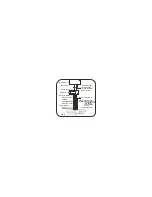
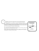
Page 15: ...Fig 7 ...

Page 16: ...ith the fan s specification DO NOT EXCEED THE MAXIMUM WATTAGE RATING Step 1 Install 1x100W halogen bulb included into bulb socket Fig 8 Step 2 Raise glass shade up against bottom of fan housing and secure it to the fan by turning the glass shade clockwise until snug DO NOT OVERTIGHTEN Fig 8 NOTE The metal light cover included with your fan is an option to replace the glass for the light in the eve...

Page 17: ...er clockwise When installing the glass onto the light plate you ll notice there are 3 pressure clips around the surface of the plate These are meant to help ease the removing of the glass in the future for any maintenance that maybe be needed to the fan Fig 9 PRESSURE CLIPS ...

Page 18: ...l cycle between bright and dim settings as long as the button is pressed The light key has an automatic auto resume feature that allows the light to remain at the same brightness as the last time it was turned off D OFF ON Slide Button Wall Control Fans Only This button turns the power Off and On to the Fan and Light s E Button Full Function Remote Control Units Only This button is used to change ...

Page 19: ...m Weather forward A DOWNWARD airflow creates a cooling effect as shown in Figure 10 This allows you to set your air conditioner on a warmer setting without affecting your comfort Cool Weather Reverse An UPWARD airflow moves warmer air off the ceiling area as shown in Figure 11 This allows you to set your heating unit on a cooler setting without affecting your comfort SUMMER OPERATION WINTER OPERAT...

Page 20: ...acquer to minimize discoloration or tarnishing Do not use water when cleaning this could damage the motor wood blades or possibly cause an electrical shock 3 Use a lint free lightly damp cloth or duster to remove dust from the blades 4 There is no need to oil your fan The motor has permanently lubricated bearings 5 If your fan is provided with glass shades clean with lukewarm soapy water and a sof...

Page 21: ... the wall switch is turned on Check circuit fuses or breakers Caution Make sure the power is turned off before performing the following steps Remove canopy and check wire connections Check wall control transmitter connections if applicable Note Fan must be installed at a maximum distance of 40 feet from the transmitting unit for proper signal transmission between the transmitting unit and the fan ...

Page 22: ...n s AC power ON Press the transmitter s Stop button and hold the Stop button for 10 seconds Once the receiver has detected the set frequency the down light of your fan if applicable will blink twice there is no indication if your fan is not equipped with a light The receiver has now learn the frequency which has been selected on the transmitter After completing the steps above you should be able t...

Page 23: ... 3450 6300 120 120 Fan Size Speed Volts Amps Watts Low Medium High SPECIFICATIONS These are typical readings Your actual fan may vary They do not include amps and wattage used by the light s For any additional information about your Minka Aire Ceiling fan please write to R 1151 W Bradford Court Corona CA 92882 For Customer Assistance Call 1 800 307 3267 12 14 kgs 14 03 kgs 2 55 10 9 kgs 12 44 kgs ...

Reviews: