Mission 77 Series Loudspeakers
User Instructions
1
Welcome to Mission!
The 77 Series is the latest in a long line of distinguished Mission
loudspeakers. These technologically advanced loudspeakers will
compliment the finest electronics and décor.
Patented Aerogel membrane bass drivers and advanced neodymium
tweeters are used throughout the range. A critically tuned suspension
ring mechanically de-couples the tweeter housing from the rest of the
cabinet. High-purity nickel-plated binding posts feature on all models.
Your Mission 77 Series loudspeaker system will bring you great listening
pleasure for many years.
General Information
Please read these instructions carefully before installing your
loudspeakers. A few minutes studying this manual will ensure superb
performance from your loudspeakers for many years.
Unpacking Your Loudspeakers
•
Remove all the staples and sealing tape from the carton.
•
Carefully unpack each loudspeaker.
•
Retain all the packing materials so that your loudspeaker can be
repacked and shipped without damage.
Fitting Spikes – Models 773 - 775
Refer to Fig.1 and 2 on the fold out page.
•
Invert the loudspeaker and place the top on a soft surface.
•
Screw a nut on each spike and place a washer over the nut.
•
Screw the spikes into the bushes fitted in the base of the cabinet.
•
Carefully return the loudspeaker to its normal position.
•
Adjust the height by screwing in or out one or more of the spikes
until the loudspeaker is stable and level.
An outrider is provided for additional stability.
To fit this unit:
•
Place the outrider over the rear of the cabinet base.
•
With the screws supplied, attach the outrider securely to the rear
mounting bushes in the cabinet. Now attach the rear spikes to the
bushes on the outrider.
•
Install the front spikes and complete the installation as above.
Connecting Your Loudspeakers
Conventional Loudspeaker Connections
Loudspeaker cable is polarity coded along one edge. Split the cable to a
depth of about 25mm and strip 8mm of insulation from each wire. If the
cable is stranded, twist the strands together.
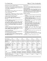
Bi-Wiring & Bi-Amping
Mission models 772 – 775 can be bi-wired for improved performance.
Remove both pairs of shorting links and connect a cable to each pair of
terminals, running them to a common connection at the amplifier output
terminals. In the figure below, the terminal panel on the left is bi-wired; the
panel on the right is conventionally wired. Note the shorting links.
Positioning Your Loudspeakers
Refer to Fig 3. on the fold-out page.
Mission 773, 774 and 775 loudspeakers should be placed on the floor
(ideally on spikes).
Mission 771 and 772 should be mounted on rigid stands, such as Mission
‘Stance’, ideally spike coupled to the floor. Height is important: A stand
should place a loudspeaker’s tweeters at ear level to a seated listener.
Shelf or bracket mounting is second best.
The distance from the rear wall can profoundly affect loudspeakers’ sonic
performance. If your speakers are too close to the wall the bass will boom
and sound coloured. Moving them into the room may increase clarity but
tends to reduce bass output. When positioned correctly, the high
frequency response is smooth with well-defined, powerful bass.
Start with the speakers about 20cm from the wall and 1.8 metres apart.
The distance from each loudspeaker to the side wall should be at least
0.5 metres. Vary the distance between the two loudspeakers and the
distance from the wall until you get a perfect stereo stage.
A few minutes optimising you’re listening position will be rewarded with a
soundstage limited only by the quality of your equipment.
Phase
To check that your loudspeakers are in phase, check the polarity of your
speaker wire at the terminal post on the loudspeakers and at the
loudspeaker connector on your amplifier. The marked conductor should
always be connected to the positive terminals.
If your loudspeakers are wired correctly, the sound should be full with
clean treble and a deep, rich bass.
Ancillary Equipment
Your loudspeaker cables have a noticeable effect on sound quality. After
extensive research, Mission has developed
Duet
and
Quartet,
cables for
standard and bi-wiring applications. Additionally, MISSION
and
CYRUS
amplification provides outstanding fidelity with wide system dynamics and
will optimise the performance of your loudspeakers.
HF
LF
By using separate amplifiers for LF
and HF drive units you can further
improve performance. This is
known as bi-amping.
The illustration opposite shows one
channel of a bi-amped system.
Note that the amplifier inputs are
linked.
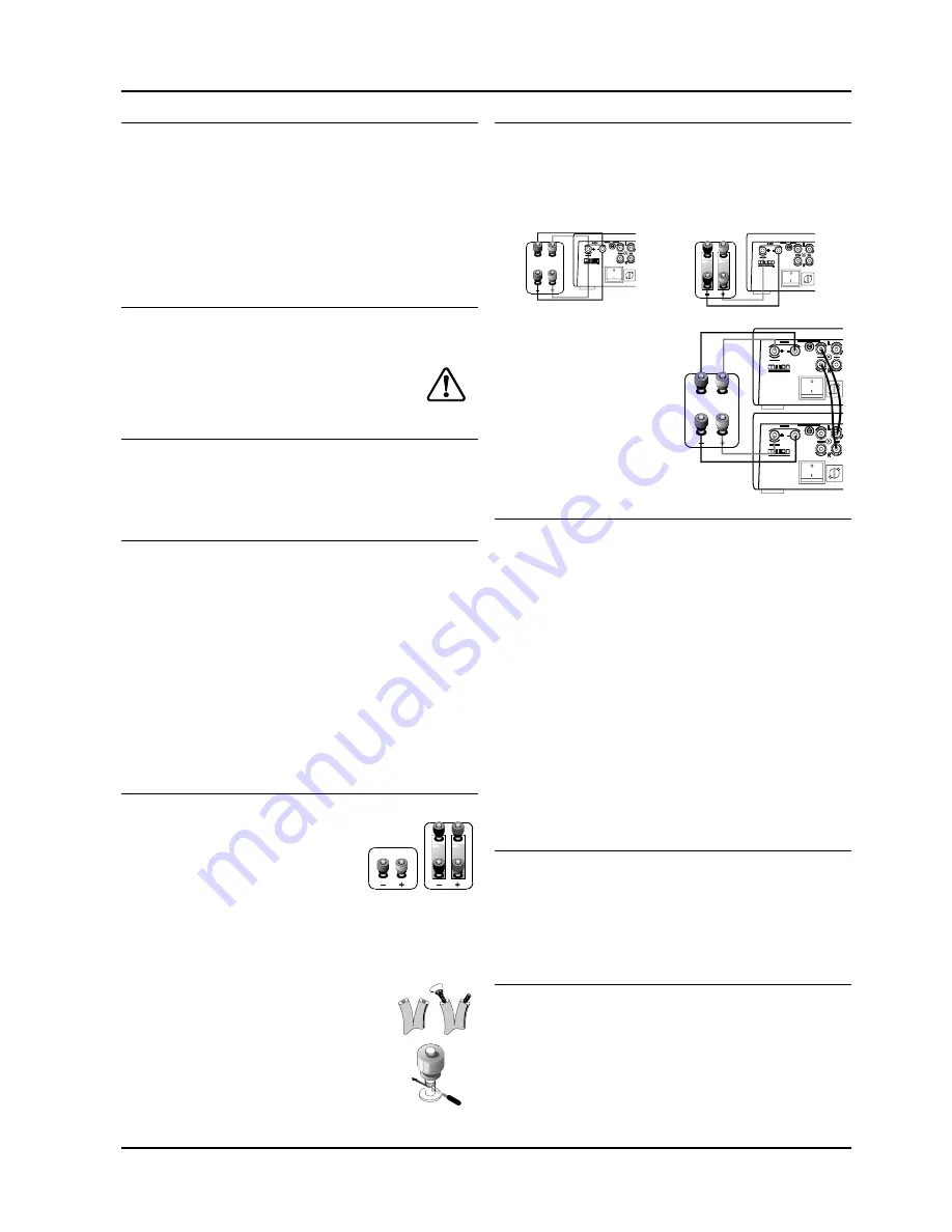
Unscrew each terminal. Thread the bare end of the
cable through the cross-hole ensuring there are no
loose strands. Tighten securely.
Connect the red, positive (+) terminal of the Left
loudspeaker to the corresponding red, positive (+)
amplifier terminal. Connect the black, negative (-)
terminals similarly. Repeat for the Right Channel
.
Terminal Panels
Your loudspeakers use two or four terminals.
When connecting a four-terminal panel
conventionally, ensure that the shorting links
are installed as shown.
Please pay attention to all cautions printed on the
pages marked with this symbol ..........................................
771
77C
772 - 775
HF
LF
HF
LF
HF
LF