background image

A180E388P03

INSTRUCTION MANUAL

SINGLE-NEEDLE LOCKSTITCH UPPER AND LOWER FEED
AUTOMATIC UNDERTRIMMER
INDUSTRIAL SEWING MACHINE

LY2-3310-B1T

MODEL

Summary of Contents for LY2-3310-B1T

Page 1: ...A180E388P03 INSTRUCTION MANUAL SINGLE NEEDLE LOCKSTITCH UPPER AND LOWER FEED AUTOMATIC UNDERTRIMMER INDUSTRIAL SEWING MACHINE LY2 3310 B1T MODEL ...

Page 2: ...ion 1 If the machine s oil pan has an oil sump never operate the machine without filling oil in it 2 If the machine is lubricated by a drop oiler never operate the machine without lubricating 3 When a new sewing machine is operated verify the rotational direction of the pulley with the power on The pulley should rotate counterclockwise when viewed from the pulley 4 Verify voltage and single or thr...

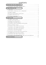
Page 3: ...5 2 Winding of the bobbin thread 5 3 Threading of the needle thread 6 4 Adjustment of feed stitch length and backstitch 6 5 Balance of threads tension 6 6 Adjustment of the needle thread tension 6 7 Adjustment of the bobbin thread tension 7 8 Adjustment of the presser foot pressure 7 9 Adjustment of the feed dog height 7 Adjustment of the feed foot and the presser foot 8 A To handle thread at the ...

Page 4: ...sition When the pedal is Neutral the machine stops at Down position If marks deviate large than 2 mm adjust as follows 1 Disconnect the plug 12pins of cable from the machine head 2 Run the machine and stop at Down position 3 While holding the pulley insert the Adjusting tool in the hole Ⓑ then turn the tool 3 Confirm the stop operation then set the plug 12pins coming from the machine head into the...

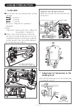
Page 5: ...ne left out of use for considerably long time is used again replenish a suitable amount of oil to the portions indicated by arrows in the below figure 2 Adjustment of lubrication to the rotating hook Adjust the lubrication amount of the rotating hook by turning the screw Ⓐ USAGE PRECAUTION At and please lubricate the oil braid under the rubber plug Ⓐ Screw Ⓐ Decrease Increase Line Hole for supply ...

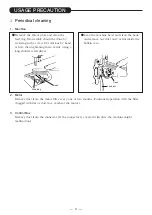
Page 6: ... the connector If the connector is covered with dust the machine might malfunction USAGE PRECAUTION Hook Feed dog Hook Feed bar Remove the throat plate and clean the feed dog Reassembly should be done by screwing in the screw 2 3 rotations by hand at first then tightening them evenly using a long shafted screwdriver Lean the machine head and clean the hook and remove any dust and or lint inside th...

Page 7: ...d the normal operation is resumed by turning off the power once then turning on again The same operation occurs for the detector malfunction or the line breakage 5 Installation of the belt cover 1 Install the belt cover on the machine side for safety Refer to the provided instruction document contained in the same package 2 Install the belt cover on the motor side for safety 6 Precaution on operat...

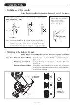
Page 8: ...pacity Winding amount adjustment screw Thread guide HOW TO USE 1 Installation of the needle Note Before installing the needles be sure to turn off the power Insert the needle upto the bottom of needle clamp and tighten the screw keeping the long groove side facing to the left Insufficient insertion Needle distorted Gap Long groove left side Timing mark for DB 1 Timing mark for DP 17 Needle bar Not...

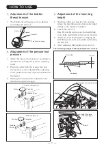
Page 9: ...ent of feed stitch length Adjust feed length by turning the feed length setting dial while pushing PUSH lever Backstitch Direction of stitching can be reversed by depressing the reverse sewing lever or pushing the touch back switch Touch back switch In the case that the switch is turned to the arrow direction by 180 no backward stitching occurs even when the switch is pushed Use this function to a...

Page 10: ...the pulley and stop it at the position where the feed lifting rock shaft crank right swings to the innermost position 2 Loosen the screw Ⓐ Note Be careful not to move the feed lifting rock shaft crank right in the lateral direction 3 Adjust the feed dog height by swinging the feed lifting rock shaft crank left and moving the feed bar 4 After adjusting fully tighten the screw Ⓐ The feed dog height ...

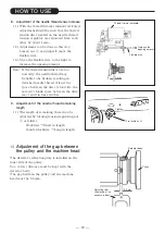
Page 11: ...ment height of the presser foot and feed foot Note When sewing a thin fabric the up and down movement should be adjusted at minimum To adjust loosen the screw and shift the position of crank rod boss Upward The up and down movement will increase Max 5 mm Downward The up and down movement will decrease Min 2 mm 3 A gap between the feed foot and the presser foot Note At the condition the stitch leng...

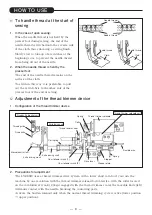
Page 12: ...r devise 2 Precautions for adjustment The LY2 3310 uses a thread trimmer drive system with a lower shaft cam So if you turn the machine by one revolution with the thread trimmer solenoid activated i e with the roller located on the cam follower crank 2 kept engaged with the thread trimmer cam the movable knife left will make contact with the needle breaking the contacting parts Activate the built ...

Page 13: ... driving shaft 4 The stopper must be set to the flat on the knife driving shaft in such a way that the knife driving shaft is snug and smoothly turns in the shaft direction 5 Installing the thread trimmer solenoid unit 1 Operation stroke of the thread trimmer solenoid Standard operation stroke is 6 mm This stroke can be adjusted by using nut Ⓐ 2 Installing the unit The unit can be mounted by using...

Page 14: ... engaging amount of knives is 1 5 to 2 0 mm The engaging amount can be adjusted by properly mounting the driving crank 3 Adjustment of knives engaging pressure See the illustration In such a situation the movable knife left and the fixed knife should first make contact with each other This situation is standard If a thread is poorly cut particularly when it is thick slightly increase the engaging ...

Page 15: ...ws Clockwise Short in length Counterclockwise Long in length C Adjustment of the gap between the pulley and the machine head The detector s reflection plate is installed on the inner side of the pulley So a correct distance must be kept with the detector body The gap between the pulley and the machine head must be 6 5 mm Note If the thread tension discs are too narrowly the needle thread may be li...

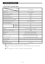
Page 16: ...tating hook Large Bobbin case With racing prevention spring Bobbin Made of steel for thread trimmer Lubrication system Manual lubrication The hook is supplied with oil automatically from the tank Thread trimmer Rotary trimming by left movable knife and right fixed knife Touch back Bed dimensions mm 475 178 Note The bobbin should be of high quality free from deformation Some materials and or sewing...

Page 17: ......

Page 18: ......

Page 19: ......

Page 20: ...Printed in Japan ...

Reviews: