background image

• Design specifications are subject to change without notice.

MITSUBISHI DIGITAL ELECTRONICS AMERICA, INC.

9351 Jeronimo Road, Irvine, CA  92618-1904

Copyright  ©  2009  Mitsubishi Digital Electronics America, Inc.

All Rights Reserved

CAUTION:

Before servicing this chassis, it is important that the service person read the "SAFETY PRECAUTIONS" and

"PRODUCT SAFETY NOTICE" contained in this manual.

Ser

Ser

Ser

Ser

Service

vice

vice

vice

vice

Manual

Manual

Manual

Manual

Manual

2009

2009

2009

2009

2009

MITSUBISHI ELECTRIC

LCD FLAT PANEL TELEVISION

VLP41 / VLP41+ / VLP41++ CHASSIS

•  Analog Output

: AUDIO / SUBWOOFER OUT JACK

   Level

(RCA Type)

-4.7dBm 4.7k

Ω 

unbalanced

•  Analog Input

:  VIDEO IN JACK (RCA Type)


Level

   Y - 1.0Vp-p, Cr, Cb - 700mVp-p

75

 unbalanced

• Digital

: HDMI

TM

 1.3 Inputs


Inputs/Outputs

480i, 480p, 720p, 1080i (60Hz)

1080p(24Hz, 30Hz, 60Hz)

: Digital Audio Input (AC-3,


PCM)

: Digital Audio Output (AC-3, PCM)
: USB Input

: Direct IR Input/NetCommand Ouput

(V41+, V41++)

: RS-232c (V41++)

: Ethernet Wired Internet Connector

(V41++)

• HDMI

TM

 Digital PC Compatibilty

: 640 x 480, 898 x 480, 800 x 600,

1064 x 600, 1024 x768, 1280 x 720,

1365 x 768, 1280 x 1034 @ 60Hz,

1920 x 1080 @ 24Hz, 30Hz, 60Hz

VLP41 Chassis

LT-40151
LT-46151
LT-52151

Pb Solder

VLP41++ Chassis

LT-46249
LT-52249

SPECIFICATIONS

• Power Input

: AC 120V, 60Hz

Power Usage

: See table on page 5

• Dimensions

: See table on page 5

& Weight

• LCD Panel

: Resolution - 1920 x 1080

: Refresh Rate - 120 Hz

• Tuning

: Digital/Analog Tuner

  (NTSC/ATSC/QAM)

• Tuning Range

: Analog Cable - 1~125

  Digital Cable - 1~135

Antenna Input

: 1 RF 75 Ohms unbalanced

• Speakers

: 2W x 16 (V41/V41+)

: 2W x 16 & 20W x 2 (V41++)

VLP41+ Chassis

LT-40153
LT-46153
LT-52153

Lead-Free solder PWBs

LT-52249

Summary of Contents for Unisen LT-40151

Page 1: ...unbalanced Digital HDMITM 1 3 Inputs Inputs Outputs 480i 480p 720p 1080i 60Hz 1080p 24Hz 30Hz 60Hz Digital Audio Input AC 3 PCM Digital Audio Output AC 3 PCM USB Input Direct IR Input NetCommand Ouput V41 V41 RS 232c V41 Ethernet Wired Internet Connector V41 HDMITM Digital PC Compatibilty 640 x 480 898 x 480 800 x 600 1064 x 600 1024 x768 1280 x 720 1365 x 768 1280 x 1034 60Hz 1920 x 1080 24Hz 30H...

Page 2: ... HDMI is a trademark of HDMI Licensing LLC Dolby and Dolby Digital are registered trademarks of Dolby Laboratories ...

Page 3: ... 12 PowerAssembly Removal 12 PWB POWER Replacment 12 Main Assembly Removal 13 PWB MAIN Replacment 13 Top Bottom Side Brackets Removal 14 Top Stay Removal 14 LCD Panel Replacement Final Steps Wiring and Wiring Clamps 15 INITIALIZATION INITIAL SETTINGS TROUBLESHOOTING 19 Remote Control 19 Option Menu 20 Reset and Initialization 20 Initial Settings 21 A V Reset 22 Backup Restore ISF Settings 23 LED I...

Page 4: ...T 46249 LT 52249 CIRCUITRY BLOCK DIAGRAMS 37 Power Supply Overview 37 5VSL Source 38 5VSL Distribution 39 340V Source 40 PWB ML POWER 41 OVINV 12VS PANEL VCC Sources 42 12VS Distribution 1 2 43 12VS Distribution 2 2 44 Signal Path 45 System Control 46 SCHEMATIC DIAGRAMS ...

Page 5: ...eristics are identified in this service manual Electrical components having such features are identified by shading on the schematic diagram and parts list of this service manual Therefore the replacement for any safety part should be identical in value and characteris tics Pb Solder The PWBs used in thischassis are constructed using Lead Free solder When servicing use only recommended Lead Free s...

Page 6: ...nd safety related notes located inside the receiver cabinet and on the receiver chassis WARNING 1 Operation of this receiver outside the cabinet or with the cover removed presents a shock hazard from the receiver s power supplies Work on the receiver should not be attempted by anyone who is not thoroughly familiar with the precautions necessary when working on high voltage equipment 2 Do not insta...

Page 7: ...DISASSEMBLY Stand Removal NOTE The Stand can be removed either before or after Back Cover removal 1 Lay the TV face down on a soft flat surface 2 Remove screws C and lift out NOTE Unless noted instructions are for all models Illustrations may differ slightly depending upon the actual model being serviced LCD Panel Replacement 1 Remove the parts noted with 2 Reverse the procedure to install a repla...

Page 8: ...een Size Screw Quantity 52 10 46 8 40 6 Speaker Cabinet Disassembly LT 40151 LT 46151 LT 52151 LT 46153 LT 52153 1 GRILL REAR Remove screws B 2 PreampAssembly Remove screw C 3 LED Assembly Remove screw D 4 PLATE LED Remove screws E DISASSEMBLY PARTS REPLACEMENT CONTINUED B ORNAMENT B E NET SP GRILL REAR PWB PREAMP PLATE IR C LENS IR PLATE LED D PWB LED COVER LED GRILL SP SPEAKER 2W PAD SP SPEAKER ...

Page 9: ...ENS IR PLATE IR B C D SPEAKER GRILL SP GRILL REAR NET SP SPEAKER 2W PAD SP LENS LED PWB SBL PLATE LED PWB LED E HOLDER SP BEZEL FRONT Removal 1 Remove the Speaker Cabinet 2 Release the clips arond the sides and top of the Bezel and lift away from the front of the LCD Panel BEZEL FRONT Replacement LT 40153 LT 46153 LT 52153 LT46249 LT 52249 1 Apply double faced adhesive tape along the inside top bo...

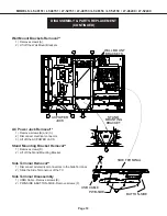
Page 10: ...ARTS REPLACEMENT CONTINUED AC Power Jack Removal 1 Remove screws B and C 2 Disconnect electrical connector 3 Lift off the AC POWER JACK Side Terminal Removal 1 Disconnect all electrical connectors to the Side Terminal 2 Slide the Side Terminal out of the TV Side Terminal Disassembly 1 HDMI Cable Remove screws E 2 PWB SIDE BUTTON SIDE Remove screws F A A WALL MOUNT BRACKETS A STAND BRACKET MOUNTING...

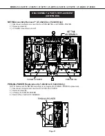
Page 11: ... screws A 3 Lift Net MLAssembly up and off PWB ML POWER Replacement LT 46249 LT 52249 Only NOTE Removal of the NET ML Assembly is not required for PWB ML POWER replacement 1 Disconnect all electrical connectors from PWB ML POWER 2 Remove screws B 3 Lift away the PWB ML POWER 4 Reverse the procedure for installation DISASSEMBLY PARTS REPLACEMENT CONTINUED A A NET ML ASSEMBLY PWB NET ML PWB ML POWER...

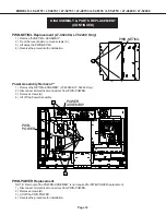
Page 12: ...y Removal 1 Remove the NET ML ASSEMBLY LT 46249 LT 52249 Only 2 Disconnect all electrical connectors from PWB POWER 3 Remove screws A 4 Lift off the Power Assembly PWB POWER Replacement NOTE Removal of the POWER ASSEMBLY is not required for PWB POWER replacement 1 Disconnect all electrical connectors from PWB POWER 2 Remove screws B 3 Lift off the PWB POWER 4 Reverse the procedure for installation...

Page 13: ...e PWB MAIN is replaced as an assembly that includes the shield 1 Remove the NET ML Assembly LT 46249 LT 52249 Only 2 Disconnect all electrical connectors from PWB MAIN 3 Remove screws A 4 Lift off the Main Assembly 5 To install a replacement PWB MAIN reverse the procedure DISASSEMBLY PARTS REPLACEMENT CONTINUED A A MAIN ASSEMBLY PWB MAIN ...

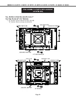
Page 14: ...REPLACEMENT CONTINUED Top Bottom Side Brackets Removal Top Stay Removal 52 Models 1 40 and 46 models Remove screws A B 52 models Remove screws A B C A 40 46 MODELS BRACKET SIDE BRACKET SIDE BRACKET TOP BRACKET BOTTOM A A A B C 52 MODELS BRACKET SIDE BRACKET SIDE BRACKET TOP BRACKET BOTTOM A A C B STAY TOP ...

Page 15: ...ONTINUED LCD Panel Replacement Final Steps Wiring and Wiring Clamps 1 To replace the LCD Panel reverse the disassembly procedure 2 Install the wiring and wiring clamps as shown in the following diagrams WIRING CLAMP LOCATIONS LT 40151 LT 40153 CLAMP CLAMP CLAMP WIRING CLAMP LOCATIONS LT 46151 LT 46153 CLAMP CLAMP CLAMP ...

Page 16: ... 40151 LT 46151 LT 52151 LT 40153 LT 46153 LT 52153 LT 46249 LT 52249 DISASSEMBLY PARTS REPLACEMENT CONTINUED WIRING CLAMP LOCATIONS LT 46249 CLAMP CLAMP CLAMP WIRING CLAMP LOCATIONS LT 52151 LT 52153 CLAMP CLAMP CLAMP ...

Page 17: ...Page 17 MODELS LT 40151 LT 46151 LT 52151 LT 40153 LT 46153 LT 52153 LT 46249 LT 52249 DISASSEMBLY PARTS REPLACEMENT CONTINUED WIRING CLAMP LOCATIONS LT 52249 CLAMP CLAMP CLAMP ...

Page 18: ...ice functions and adjustments can be performed with either the old or new versions However several buttons have different names or labels The remote buttons associated with service that have been changed are shown below with the old buttons name in parenthesis For full remote instructions refer to the Owner s Guide REMOTE CONTROL ACTIVITY INPUT or DEVICE LAST QV PAGE UP AUDIO PAGE DOWN VIDEO NEW B...

Page 19: ...e to a Digital Channel 2 From the Option Menu scroll down and highlight Digital Signal Strength 3 Press ENTER The screen will display the Digital Signal Strength Menu SNR Recommended Levels 8VSB 16 to 33 64 QAM 22 to 35 256 QAM 27 to 38 OPTION MENU Option Menu MENU 2 4 7 0 Initialize Power Restore OFF Production Mode OFF Digital Signal Strength 1 9 NetCommand Software Vxx xxx xx Total hours of use...

Page 20: ...release the button 3 Enter the code 9 9 3 The remote will now operate the TV s volume and mute when the slide switch is in the TV CABLE SAT VCR or DVD positions A V Memory Reset by individual input When the audio and or video settings for a single input seems to be incorrect All Audio and Video settings for the individual input are reset except for the Listen To Language Balance and Closed Caption...

Page 21: ...u Standard Audio only screen saver On Name Film Mode Off Antenna On Smooth 120 Film VLP41 41 Standard Input 1 Gray out Smooth 120 Film VLP41 5 Input 2 Gray out Blue Glow VLP41 only On Input 3 Gray out Test Picture HDMI 1 Gray out Picture Plus HDMI 2 Gray out PerfectColor 31 All colors HDMI 3 Gray out PerfectTint 31 All colors HDMI 4 Gray out Advanced Picture Learn VLP41 41 Gray out Captions Menu A...

Page 22: ...er 31 Center 31 Center 31 Center 31 Center 31 Sharpness Center 31 Center 31 Center 31 Center 31 Center 31 Color Temperature High High High High Low fixed Video Noise Mid Mid Off grey out Off Off SharpEdge VLP41 On On On Off Off DeepFieldImager VLP41 On On On Off Off Smooth120 Film Motion Off Off Off Off Off Film Mode Off Off Off Off Off H Position 31 V Position 31 Super Resolution Off Gamma 2 4 de...

Page 23: ...e ISF Settings 1 Insert the USB memory device with the backup data into the USB slot 2 Press the MENU button on the remote control The Customer Menu will appear 3 Press the 2 4 5 7 buttons The Service Menu will appear 4 Press the 0 button The Data Selection Menu will appear See above 5 Use the TS buttons to select BACKUPAND RESTORE ISF SETTING and press ENTER 6 Use the TS buttons to toggle to Rest...

Page 24: ...an abnormal condition If the TV is switched Off AC is removed or a System Reset is performed the code automatically resets to 12 No Error See the Error Code Log to retrieve a history of errors Note Use the front panel buttons not the remote control Note If there is no response the front panel may be locked by a V Chip setting To unlock press and hold ACTIVITY on the front panel for 5 seconds LED I...

Page 25: ...Previous Page Press Down to Next Page Press Right to Top Page Press Left to Last Page Press CANCEL to Initialize Press MENU to Exit NOTE The Error Code Log is intended as a reference tool and is not meant to be used as a final determination of a defective part SOUND PROJECTOR TRANSDUCER TEST This procedure will test will each of the TV s speakers individually using an internal white noise generato...

Page 26: ...ratures can cause surface oxidation resulting in poor solder spread ability and wet ability The flux is more corrosive The time required for a good solder connection may take longer Poor wet ability can cause solder balls Higher temperatures can cause flux spattering Soldering iron tip life is shortened Dull finish solder joints not shiny can appear to be a cold solder joint In general a tip tempe...

Page 27: ...e the chip parts carefully so as not to tear the copper foil from the printed circuit board 3 Discard removed chips do not reuse them 4 Do not apply heat for more than 3 three seconds to new chip parts 5 Avoid using a rubbing stroke when soldering 6 Take care not to scratch or damage the chip parts when soldering 7 Supplementary cementing is not required Chip Parts Removal Resistors Capacitors etc...

Page 28: ...s will result Critical and Warranty Parts Designation Critical Electrical Components are indicated by Bold Type and a icon in the Parts List and in the schematic diagrams by a red hatch and a Parts Tolerance Codes Refer to the following chart for tolerance characteristics of electrical components MARK B C D F G J K Tolerance 0 1 0 25 0 5 1 2 5 10 MARK M N V X Z P Q Tolerance 20 30 10 40 80 100 30 ...

Page 29: ...34C335003 934C335004 934C335001 934C335002 934C335007 934C335005 934C335006 934C335008 ASSY PWB POWER 934C336001 934C336002 934C336003 934C336002 934C336003 ASSY PWB SIDE 934C334001 ASSY PWB LED 934D066001 ASSY PWB PREAMP 934D067001 934D067002 934D067001 934D067002 934D067001 934D067002 ASSY PWB SBL 934D076001 934D076001 ASSY PWB NET ML 934C339001 934C339001 ASSY PWB MLPOWER 934C342001 934C342001 ...

Page 30: ...IC3J01 276P606010 IC C MOS MAX9715 IC3J10 276P606010 IC C MOS MAX9715 IC3J20 276P606010 IC C MOS MAX9715 IC3J30 276P606010 IC C MOS MAX9715 IC3J40 276P606010 IC C MOS MAX9715 IC3J50 276P606010 IC C MOS MAX9715 IC3J60 276P606010 IC C MOS MAX9715 IC3J70 276P606010 IC C MOS MAX9715 IC3K00 271P254010 IC ISL6545ACBZ TS2698 IC4A01 276P742020 IC C MOS PST8428NR IC4A02 276P687010 IC C MOS BCM3549LKFSB5G I...

Reviews: