background image

TIME LAPSE VIDEO CASSETTE RECORDER

INSTALLATION AND
OPERATION MANUAL

MODEL

HS-S8300E(BRS)

ONLY VIDEO CASSETTE TAPES WITH THE 

MARK OR THE 

V

 MARK MAY BE USED WITH THIS MODEL.

THIS INSTRUCTION MANUAL IS IMPORTANT TO YOU.
PLEASE READ IT BEFORE USING YOUR VIDEO CASSETTE RECORDER.

REW

FF

JOG/ADJUST

CLEAR/

ENTER/

SHUTTLE

REC

STOP

PLAY

POWER

EJECT

PICTURE

TRACKING

POSITION/
VERTICAL
ADJUST

REC/PLAY

                 MODE

COUNTER

RESET

COUNTER MEMORY/

SKIP/INDEX

PAUSE/

SHUTTLE HOLD

DISPLAY

TIMER REC

SOFT

SHARP

S-VHS

OFF

ON

625

VHS

PAL

Summary of Contents for HS-S8300E(BRS)

Page 1: ...SED WITH THIS MODEL THIS INSTRUCTION MANUAL IS IMPORTANT TO YOU PLEASE READ IT BEFORE USING YOUR VIDEO CASSETTE RECORDER REW FF JOG ADJUST CLEAR ENTER SHUTTLE REC STOP PLAY POWER EJECT PICTURE TRACKIN...

Page 2: ...outlet first Then unplug the lead by gripping the plug not the lead and carefully remove the plug from the mains outlet NEVER TOUCH OR INSERT ANY OBJECT INSIDE THE VCR Touching the inside of the cabi...

Page 3: ...The Elapsed Time of recording and playback is stored in a non volatile memory IC The elapsed time display should be used as a guide as to when periodic maintenance should be carried out Tape use count...

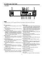
Page 4: ...REC PLAY MODE buttons Set to 3H L12H L24H 48H 960H or 0H mode to select recording speed Set to 3H L12H 12H L24H 24H 48H 960H or 0H mode to select playback speed during playback recorded in SP mode D C...

Page 5: ...dicator Flashes during alarm recording and stays on when the alarm recording is finished 4 INDEX indicator Flashes during recording of date hour index signal at the change of the hour and during recor...

Page 6: ...m during recording A RESET button When pressed the present time alarm recording list power loss list and the number of tape use will be erased While the button is pressed the power is cut off from the...

Page 7: ...which is recorded in 3H mode with this VCR and press the PAUSE button If the vibration occurs during normal playback in L12H or L24H mode playback a tape in each playback mode 2 Press the VERTICAL ADJ...

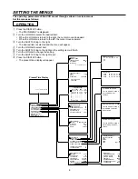
Page 8: ...then all MENU will be initialized POWER LOSS LIST CLEAR Turn the SHUTTLE RING then POWER LOSS LIST will be cleared ALARM LIST CLEAR Turn the SHUTTLE RING then ALARM LIST will be cleared 0001 01 05 99...

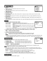
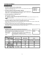
Page 9: ...letters becomes small LARGE The size of the letters becomes large 3 SETTING THE BACKGROUND COLOUR BLUE BACK ON The blue screen overlays on the recorded picture when menu is displayed on the monitor OF...

Page 10: ...ignal is output as shown below RECORDING SET UP 1 SETTING THE ALARM REC MODE ALARM REC MODE Sets the alarm recording time mode When the JOG dial is turned the display will be switched in the order of...

Page 11: ...ill be displayed 0 0H MAINTENANCE POWER LOSS LIST ALARM LIST ALL MENU INITIALIZE POWER LOSS LIST CLEAR ALARM LIST CLEAR REPEAT REC TIMES ELAPSED TIME 2 SETTING THE FREQUENCY DIVISION RATIO CLOCK OUT S...

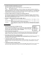
Page 12: ...ust be set according to the tape being used E 180 When using E 180 tape or SE 180 tape E 240 When using E 240 tape or SE 240 tape 4 SETTING THE VIDEO MODE VIDEO MODE COLOUR Select for colour recording...

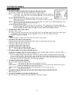
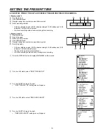
Page 13: ...the monitor 2 Turn the JOG dial to select FIRST TIME SET UP 3 Turn the SHUTTLE ring to the right FIRST TIME SET UP setting menu will appear 4 Turn the JOG dial to select TIME DATE ADJUST 5 Turn the SH...

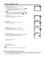
Page 14: ...A Setting the present time Turn the SHUTTLE ring to the right The hour digits of TIME display will flash Turn the JOG dial to set the hour digits of the present time Set the 10 minutes digit and 1 min...

Page 15: ...has a protection circuit which will eject the tape if it is loaded improperly If the VCR ejects the tape you are trying to load remove it completely and check that the long narrow edge with the conten...

Page 16: ...with other VCRs Time Lapse recordings can be played correctly by other VHS compatible Time Lapse Recorders when the recording interval and head type SP matches the recording 2 RECORDING MODE When the...

Page 17: ...the number of times a tape has been repeatedly recorded on The number of tape use counts up by one when the tape ends The number of tape use is memorised even if the mains supply is removed provided t...

Page 18: ...n ONE SHOT INTERVAL For Interval recording choose the interval time from 10S second to 3M minute in ONE SHOT INTERVAL 4 Press the REC button One shot recording will be on STANDBY mode Interval recordi...

Page 19: ...ing in the same record mode as before the power failure After the power comes back on X will be displayed next to the present time for about 1 minute If a power failure occurs during playback the VCR...

Page 20: ...of the week DW Turn the JOG dial to set the day of the week and turn the SHUTTLE ring to the right 5 Setting the recording start time START Turn the SHUTTLE ring to select the recording start time dis...

Page 21: ...ial to set the end day and turn the SHUTTLE ring to the right The start and end day cannot be set to the same day IN ORDER TO AVOID MISTAKES WHEN USING THE TIMER If an error is encountered when the TI...

Page 22: ...E CLOCK ADJUSTMENT If the ALARM REC DURATION of the RECORDING SET UP menu is set to other than MAN1 the on screen clock can be reset to the nearest hour by applying a signal to the RST RESET IN termin...

Page 23: ...inues counting When initializing the alarm recording list the alarm recording count display will be reset The alarm indicator flashes during alarm recording and lights up when the alarm recording is f...

Page 24: ...rd direction 1 Press the COUNTER MEMORY SKIP INDEX button to illuminate SKIP on the fluorescent display 2 Turn the SHUTTLE ring to the right or left ALARM RECORDING ALARM RECORDING Present position In...

Page 25: ...24H 48H 72H 96H 120H 168H 240H 360H 480H 720H 960H 0H 3H 2 4 3 PLAYBACK Tape End Selected REPEAT or ALARM PROT Playback The tape automatically rewinds to the beginning and stops Stop STOP or REWIND Fa...

Page 26: ...ying a tape press the PAUSE SHUTTLE HOLD button to freeze the picture on screen 2 Slightly rotate the JOG dial clockwise to advance the tape forward Slightly rotate it counterclockwise to reverse the...

Page 27: ...move through the picture each time the TRACKING button is pressed in L12H or L24H playback mode When a picture recorded in 3H mode is played back in L12H or L24H mode noise may appear on the screen e...

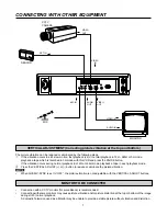
Page 28: ...to the RS 232C terminal of the personal computer b Connect the other end of cable to RS 232C IN terminal on the VCR N N N N N Refer to page 30 for the RS 232C cable configuration 2 Connecting multipl...

Page 29: ...ITER SEND Setting a character marking the end of a command When the JOG dial is turned to the right the display will be switched in the order of CR CR LF CR 6 SETTING DELIMITTER RECEIVE Setting a char...

Page 30: ...ions Before connecting the hardware unplug the power cord of the VCR from the outlet and turn the personal computer power off Connect the RS 232C IN terminal of the VCR to the personal computer s seri...

Page 31: ...mmand Command received Command carried out Sending commands from the PC etc Meaning RC CR RC CR ER02 CR Status or error code from the VCR to PC etc Command for recording Command received Failed becaus...

Page 32: ...return code 0DH and line feed code 0AH will be inputted Example 1 Fast forward the tape in the VCR of the ID number VCR02 When the DELIMITTER SEND and DELIMITTER RECEIVE of the RS 232C menu is set to...

Page 33: ...2 ST06 2 RC 2 ST07 2 RC 2 ST08 2 RC 2 ST09 2 RC 2 ST10 2 RC 2 ST11 2 RC 2 ST12 2 RC 2 ST13 2 RC 2 ST14 2 RC 2 ST15 2 RC 2 ST16 2 RC 2 ST17 2 RC 2 ST18 2 RC 2 ST19 2 RC 2 ST20 2 RC 2 ST21 2 RC 2 ST22...

Page 34: ...time Enquiry about power loss mark Move date display position 1 Horizontal 03 16 mode 1 size large 05 28 mode 1 size small 03 21 mode 2 3 size large 00 28 mode 2 3 size small 2 Vertical 02 30 mode 1 s...

Page 35: ...4 CLOCK ADJ 5 Enquiry about MODE OUT setting CALL OUT setting 0 OFF 1 ON Receive the command only when the signal at the MODE OUT terminal is switched to the active condition Enquiry about CALL OUT s...

Page 36: ...VIDEO MODE Enquiry about S VHS information Status after normal execution RC 2 AT 1 2 3 4 5 2 RC 2 EX 2 RC 2 PN 2 RC 2 PT 1 2 3 4 5 2 RC 2 EX 2 RC 2 HM 2 RC 2 WN 2 RC 2 EX 2 RC 2 RI 2 RC 2 EX 2 RC 2 Q...

Page 37: ...D HEAD NOTE 2 TAPE DECK TROUBLE Turn off the indication on the fluorescent display and on the screen by pressing the EJECT button or rewinding the tape N 1 Lack of video input signal If the VCR is set...

Page 38: ...Is the video cable connected properly or is the cable defective Is the LOCK indicator illuminated Is a cassette inserted Is the LOCK indicator illuminated Has the cassette s erasure prevention tab bee...

Page 39: ...E CALL OUT terminals screw Active L level voltage 0 0 4V output max drive current 50mA 5V DC 10mA 24V DC Non active Open max voltage 24V DC GND ALM MODE CALL OUT Interface circuit inside the VCR 2 CLK...

Page 40: ...PAUSE PLAYBACK REVERSE PLAYBACK FORWARD FRAME SHIFT FAST FORWARD REWIND Function Position 9 10 11 12 13 14 15 16 3H L24H Function Position 17 18 19 20 21 22 23 24 POWER ON OFF REVERSE FRAME SHIFT TIM...

Page 41: ...lines S VHS mode More than 240 lines VHS mode Audio Frequency Response 70Hz 7kHz 3H mode Signal to Noise Ratio Video better than 42dB Audio better than 43dB Operating Temperature 41 F 104 F 5 C to 40...

Page 42: ...872C193C3 PRINTED IN JAPAN...

Reviews: