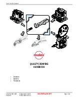
background image

The content and copyrights of the attached

 material are the property of its owner.

Distributed by:

www.Jameco.com


✦ 

1-800-831-4242

Jameco Part Number 1302713

Summary of Contents for 63811-1200

Page 1: ...The content and copyrights of the attached material are the property of its owner Distributed by www Jameco com 1 800 831 4242 Jameco Part Number 1302713 ...

Page 2: ...Quality Crimping Handbook Order No 63800 0029 Release Date 09 04 03 UNCONTROLLED COPY Page 1 of 24 Revision B Revision Date 10 07 05 QUALITY CRIMPING HANDBOOK Description Operation Maintenance ...

Page 3: ... 04 03 UNCONTROLLED COPY Page 2 of 24 Revision B Revision Date 10 07 05 Table of Contents SECTION 1 Introduction 2 Purpose 3 Scope 4 Definitions 5 Associated Materials 6 Procedure 7 Measurement 8 Process Control 9 Trouble Shooting 10 Wire Gauge Chart 11 Notes ...

Page 4: ...the crimping process are the terminal the wire and the tooling Terminal For most applications it is not economically practical for connector manufacturers to design a terminal to accept one wire size one wire stranding and one insulation diameter UL type Most terminals accommodate many wire sizes stranding and a range of insulation diameters and the terminals are designed to meet acceptable levels...

Page 5: ...imits because the attributes all interact with one another For example a track adjustment for bell mouth also will change the cut off tab length and the insulation wire position while strip length and wire locations affect the conductor brush and insulation position Adjusting the insulation crimp height may result in a slight change to the conductor crimp height measurement It may be necessary for...

Page 6: ... or automatic wire processing termination methods The handbook s contents may slightly differ from other connector manufacturers guidelines or individual company procedures This handbook provides a basic overview of what to look for in an acceptable crimp It is not intended to replace individual product and or tooling specifications Individual terminals or applications may have special requirement...

Page 7: ... shear Conductor Brush The conductor brush is made up of the wire strands that extend past the conductor crimp on the contact side of the terminal This helps ensure that mechanical compression occurs over the full length of the conductor crimp The conductor brush should not extend into the contact area Conductor Crimp This is the metallurgical compression of a terminal around the wire s conductor ...

Page 8: ...oes not specify insulation crimp heights because of the wide variety of insulation thickness material and hardness Most terminals are designed to accommodate multiple wire ranges Within the terminal s range the strain relief may not completely surround the wire or fully surround the diameter of the wire This condition will still provide an acceptable insulation crimp for most applications A large ...

Page 9: ...p enough pressure must be applied to break down the oxides that may build up on the stripped conductor and the tin plating on the inside of the terminal grip This is necessary to provide a good metal to metal contact If this does not occur resistance can increase Over crimping a crimp termination will reduce the circular area of the conductor and increase resistance Pull force testing is also a go...

Page 10: ...de that supports the top of the crimp while a pointed section determines the bottom radial surface Ruler Pocket Scale This is used to estimate the five piece measurement of bell mouth cut off tab conductor brush wire position and strip length The recommended maximum resolution is 0 50mm 020 Pull Tester Reference Figure 5 A device used to determine the mechanical strength of a crimp termination Mos...

Page 11: ... terminals under power 10 Evaluate cut off tab length and conductor bell mouth If adjustment is necessary disconnect power to the press and remove guarding Adjust track position Manually cycle the press and check the feed finger for feed location go to procedure 7 11 Evaluate conductor brush If adjustment is necessary disconnect power to the press and remove guarding Adjust wire stop for bench app...

Page 12: ...y guarding Crimp samples Adjust press position Evaluate conductor brush Disconnect power and remove necessary guards Adjust wire stop Loosen insulation crimp A Bench press or wire processing B Evaluate insulation position Crimp samples Adjust strip length Install safety guarding and connect power Adjust conductor crimp height Adjust insulation Trouble shooting See Section 9 Disconnect power and re...

Page 13: ... same size the top wire will normally result in a lower reading than the bottom wire due to the effects of the terminal serrations Wire Chart Note Pull force has only a minimum specification For CpK calculations the average reading is assumed nominal and the upper specification limit is set so CP and CpK are equal High pull force readings that increase the standard deviation can lower CpK even if ...

Page 14: ...uality Crimping Handbook Order No 63800 0029 Release Date 09 04 03 UNCONTROLLED COPY Page 13 of 24 Revision A Revision Date 09 04 03 Figure 7 3 CALIPER Figure 7 2 CRIMP MICROMETER Figure 7 1 PULL TESTING ...

Page 15: ...ts per million potential defects A 25 piece minimum sample needs to be taken from the crimping process Calculate the average and standard deviation for each specification A capability index is defined by the formula below Cp may range in value from zero to infinity with a larger value indicating a more capable process A value greater than 1 33 is considered acceptable for most applications Cp is c...

Page 16: ...thousands of terminations from being scrapped after the run is over Three and most important this data is necessary to assess and improve the crimp process Once the tooling process is setup and the wire size does not change keep one control chart for wire color changes wire length changes terminal material changes or setup adjustments Record the data point on the chart before making a crimp height...

Page 17: ...re 9 1 Wire cut depth too shallow Adjust cut depth Damaged tooling Replace tooling Cut depth too deep Adjust cut depth Cut or nicked strands Figure 9 2 Conductor not on wire center Contact wire supplier Worn tooling Replace tooling Irregular conductor cut pulled strands Figure 9 3 Wire cut depth too shallow Adjust cut depth Wire drive rollers belts worn Replace belts rollers Insulation durometer t...

Page 18: ...p position for bench applications OR re adjust press position for wire processing applications Check specification adjust strip length shorter Strip length too long Re adjust wire stop position for bench applications OR re adjust press position for wire processing applications Insulation edge centered in transition area conductor brush too long Figure 9 13 Irregular wire cut off or strands pulled ...

Page 19: ...ure 9 21 Crimp too loose not enough terminal insulation barrel Evaluate terminal Terminal contacts less than 50 of a small diameter wire Figure 9 22 Too much terminal insulation barrel Evaluate terminal Insulation crimp barrels cut through insulation into conductor strands Figure 9 23 Crimp too tight Adjust insulation crimp height Insulation not firmly gripping insulation fails bend test Figure 9 ...

Page 20: ...5 Figure 9 17 PREFFERRED INSULATION CRIMP Figure 9 18 PREFFERRED INSULATION CRIMP Figure 9 19 ACCEPTABLE INSULATION CRIMP Figure 9 20 ACCEPTABLE INSULATION CRIMP Figure 9 21 MARGINAL INSULATION CRIMP Figure 9 22 MARGINAL INSULATION CRIMP Figure 9 23 MARGINAL INSULATION CRIMP Figure 9 24 MARGINAL INSULATION CRIMP Insulation Crimps ...

Page 21: ...nged crimp tooling Changed crimp press shut height Changed press type manufacturer Changed terminal reel lot code Changed tooling set up Crimp height off target Figure 9 26 Damaged or worn tooling Adjust tooling back to target Wire variability Terminal variability Inspect incoming product Damaged loose or worn tooling Tooling replacement or tightening Measurement error Gauge capability analysis Te...

Page 22: ...mp low pull force Figure 9 29 Insulation crimp through insulation wall Raise insulation crimp height Crimp height too high Adjust crimp height Small or no conductor brush Increase strip length Conductor bell mouth too big Adjust tooling track Gold terminal application Terminal material thickness too small Evaluate the terminal application Wire pulls out of conductor grip low pull force Figure 9 29...

Page 23: ... 317 00204 26 0100 1 50 059 2600 345 15 77 6 16 1 307 00203 65 0063 1 50 059 2580 342 48 77 0 16 1 330 00206 105 0050 1 47 058 2625 348 47 78 3 18 823 00128 1 0403 1 02 040 1624 215 60 48 5 18 897 00139 7 0159 1 22 048 1770 234 93 52 8 18 811 00126 16 0100 1 19 047 1600 212 40 47 8 18 963 00149 19 0100 1 24 049 1900 252 23 56 7 18 825 00128 41 0063 1 19 047 1627 216 03 48 6 18 823 00128 65 0050 1 ...

Page 24: ...Quality Crimp Handbook Order No 63800 0029 Release Date 09 04 03 UNCONTROLLED COPY Page 23 of 24 Revision B Revision Date 10 07 05 SECTION 10 NOTES ...

Page 25: ...30 969 4550 Fax 630 505 0049 Far East North Headquarters Yamato Kanagawa Japan Tel 81 462 65 2324 Fax 81 462 65 2366 Far East South Headquarters Jurong Singapore Tel 65 268 6868 Fax 65 265 6044 European Headquarters Munich Germany Tel 49 89 413092 0 Fax 49 89 401527 Corporate Headquarters 2222 Wellington Court Lisle IL 60532 U S A Tel 1 800 78MOLEX Fax 630 969 1352 Visit our Web site at http www m...

Page 26: ...Calibration Information Hand Tool and AT Head To reduce repair time and better meet customer needs Molex has decided to outsource hand and air tool repair and calibration services to our preferred supplier QEM Inc QEM has been a supplier to Molex for many years and maintains a strong commitment to high quality in all aspects of their business This new repair and calibration arrangement will contin...

Page 27: ...inals in the proper crimping position SCOPE Wire Size Insulation Diameter Strip Length Terminal Series No AWG mm mm In mm In 50212 8100 24 30 0 20 0 05 0 80 1 40 031 055 1 30 1 80 051 071 DEFINITION OF TERMS The above terminal drawing is a generic terminal representation It is not an image of a terminal listed in the scope CONDITIONS After crimping the conductor profiles should measure the followi...

Page 28: ...ine the wire up with the conductor and insulation grips visually 4 Close the tool until the ratchet releases See Figure 3 5 Lift the locator blade or wire stop up 6 Carefully remove the crimped terminal Maintenance It is recommended that each operator of the tool be made aware of and responsible for the following maintenance steps 1 Remove dust moisture and other contaminants with a clean brush or...

Page 29: ...tool is designed for hand use only Any clamping fixturing or use of handle extensions voids this warranty Hand held crimping tools are intended for low volume prototyping or repair requirements only Caution Repetitive use of this tool should be avoided Notes 1 This tool should only be used for the terminals and wire gauges specified on this sheet 2 This tool is not adjustable for crimp height howe...

Page 30: ...STMENT RING LOCATOR BLADE 2 Figure 4 1 M4 X 18LG BHCS 3 PARTS LIST Item Number Order Number Description Quantity 1 63811 1275 Locator Assembly 1 2 11 11 0324 Spring Main 1 3 11 11 0320 Spring Ratchet 1 Not all tools are equipped with a locator or locator blade Molex Application Tooling Group 1150 E Diehl Road Naperville IL 60563 Tel 630 969 4550 Fax 630 505 0049 Visit our Web site at http www mole...

Reviews: