background image

Owner’s Guide and Installation Manual


Total fan weight with light kit 

DATE OF PURCHASE:

MODEL NUMBER:

RETAILER NAME:

RETAILER ADDRESS:

Attach sales receipt to this card and retain as your proof  of  purchase

To register your fixture, please visit our website www.montecarlofans.com

3MNLR72XXD Series Fan

 UL Model NO. : 3MNLR72

7.94 kgs

17.47 lbs

Summary of Contents for 3MNLR72 D Series

Page 1: ...it DATE OF PURCHASE MODEL NUMBER RETAILER NAME RETAILER ADDRESS Attach sales receipt to this card and retain as your proof of purchase To register your fixture please visit our website www montecarlofans com 3MNLR72XXD Series Fan UL Model NO 3MNLR72 7 94 kgs 17 47 lbs ...

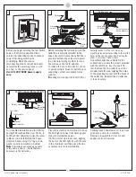
Page 2: ...o Not Remove Knockouts In The Outlet Box Mount the secondary support safety cable through the reserved nail screw hole on the outlet box to the building structure or the ceiling joist Attach the mounting bracket using only the hardware supplied with the outlet box WARNING To Reduce The Risk Of Electric Shock This Fan Must Be Installed With a general use isolating Wall Control Switch WARNING To red...

Page 3: ...h the outlet box must support 35 lbs Remove the two outlet box screws provided with the box aligning the holes of the mounting bracket with the holes of the outlet box Reinstall the 2 outlet box screws securely For Canadian installation and for USA fan and light kit combinations over 35 lbs in both flush and downrod modes the safety cable must be installed into the house structure beams using 1 5 ...

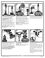
Page 4: ...ith the set screws on top side of housing Place canopy ring and canopy over downrod with column Handle it carefully to avoid damage from scratch Install ball end of downrod into mounting bracket opening To slip hanger ball into mounting bracket by slanting fan assembly for about 35 degree as shown in above illustration Align engage slot on ball with tab on mounting bracket Warning Failure to align...

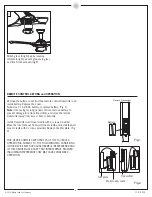
Page 5: ...rew securely Install canopy ring onto canopy by aligning the grooves in canopy ring with the tabs on canopy and pop it onto canopy Insert the blade kit and blade rubber plug in position as shown Hold the blade kit by finger and flip the blade over for installing with flywheel in step 16 Engage the blade with flywheel aligning the holes and then partially install 2 blade set screws and washers from...

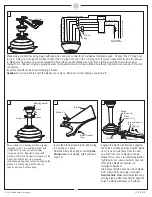
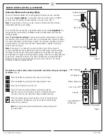
Page 6: ...ove battery to prevent damage to remote transmitter and store the remote transmitter away from excess heat or humidity Install Transmitter wall mount cradle with 2 screws provided Move the trim plate out from wall mount cradle and install the wall mount cradle with 2 screws provided Replace the trim plate Fig 2 REMOTE CONTROL SETTING and OPERATION Fig 1 Fig 2 THIS DEVICE COMPLIES WITH PART 15 OF T...

Page 7: ...h at UPPER position Your fan with the remote controller is ready to use Fig 3 Note If using universal mode your fan can be controlled with other remote transmitters with the same setting To control the fan with specific remote transmitter choose Learning Mode by placing the dip code switch at LOWER position and then make learn function setting as below Make Learn function setting at the position w...

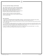
Page 8: ...tches for each fan is required if you want to separately control more than one fan in same room 4 When fan is turned on or operated forward reverse function it shutters goes back forth until it turns It is a normal performance of this fan and it will take for few seconds to run this operation The receiver provides the following protective functions Lock protection The DC motor has a build in safet...

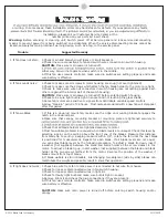
Page 9: ... If this is a downrod mount fan make sure the ridge on mounting bracket engages the notch in the downrod ball 2 Make sure that canopy mounting bracket or mounting plate are tightened securely to 4 Check that all blade holders are tightened securely to motor 5 Most fan wobble problems are caused when blade levels are unequal Check this level by selecting a point on the ceiling above the tip of one ...

Page 10: ...Nov 2014 ...

Reviews: