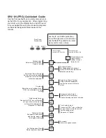
background image

SP

A

2

Pr

ogrammab

le Current/V

oltage

Limit Alarm 

T

rips

All product names are registered trademarks of their respective companies.

SPA

2

Programmable Current/Voltage

Limit Alarm Trips

June 2004
224-790-00A

HLPRG

Summary of Contents for HLPRG

Page 1: ...A 2 Programmable Current Voltage Limit Alarm Trips All product names are registered trademarks of their respective companies SPA2 Programmable Current Voltage Limit Alarm Trips June 2004 224 790 00A HLPRG ...

Page 2: ...WN pushbuttons to scroll through menus and sub menus Use the SELECT pushbutton to access menus and or make a choice CONFG INPUT CONFG OPTNS SCALE INPUT APPLY INPUT TRIM AOUT CONFG EXIT CONFG ALARM Configure Alarm Set trip point dead band high low trip delay and latching non latching CONFG PASWD TRIM INPUT Trim Input Match the actual reading of your SPA to a calibrated or known value CONFG AOUT Sca...

Page 3: ...iguration Front Panel Pushbuttons 10 Main Menu View Menu 10 Password 10 Configuring the Input 13 Configuring the Options 14 Scaling the Input 16 Applying Input Bench Scaling 17 Input Trimming 17 Configuring the Analog Output AO Option 19 Scaling the Analog Output AO Option 20 Trimming the Analog Output AO Option 21 Configuring the Alarm s 23 Password Configuration 29 ...

Page 4: ...tion Software Summary 32 Status and Tool Bar Legend 33 Configuration Screens 33 Input 33 Display 34 Alarms 35 Analog Output 37 Scaling 40 Custom Curve 40 Error Codes 42 Installation 43 Mounting 43 Making the Electrical Connections 43 Recommended Gound Wiring Practices 43 CE Conformity 43 Operation 43 Maintenance 43 Customer Support 43 ...

Page 5: ...ist ing these numbers Supply the Customer Support rep resentative with this information when calling Inputs TheSPA2 HLPRG HighLevel Programmableinput handles either current inputs from 0 50mA 1mA minimum span or voltage inputs from 0 10V 250mV minimum span Outputs Alarms The SPA2 can be ordered with two 2PRG or four 4PRG contact closure alarms Each alarm can be individuallyprogrammed 2PRG This is ...

Page 6: ...input span Current inputs 100mA of max input span WITH ANALOG OUTPUT Output Accuracy Current 0 01 of max span 2 microamps Voltage 0 01 of max span 1mV Response Time 256msec maximum 128msec typical for the output to change from 10 to 90 of its scale for an input step change of 0 to 100 Ripple up to 120Hz Current output 10mVp p when measured across a 250ohm resistor Voltage output 50mVp p max Output...

Page 7: ...ALARM C L WHEN INSTALLED WHEN INSTALLED 100mm 3 94 in 52mm 2 05 in 48mm 1 89 in 138mm 5 43 in 133mm 5 24 in 126mm 4 97 in 100mm 3 94 in 137mm 5 39 in 55mm 2 17 in REMOVE PANEL BY UNSCREWING TOP FOUR SCREWS SET PASSWORD SECURITY PASSWORD SECURITY IS OFF NO PASSWORD REQUIRED PASSWORD SECURITY IS ON PASSWORD REQUIRED BACK TX I COM V lo Source lo Sink lo Source Vo Vo lo Sink INPUT A OUT 2 SPA TOPSIDE ...

Page 8: ...o Sink Vo MR Tx COM Not Used V I Current Input Io Current Output MR Manual Reset NO Normally Open NC Normally Closed Sink Current Sink Source Current Source SPDT Single Pole Double Throw TX Power for 2 wire transmitter V Voltage Input Vo Voltage Output Vo Io Sink Io Source Io Source Output Type 2PRG SPDT Relays 4PRG SPDT Relays 2 DPDT Relays Middle Terminals Left to Right 11 12 13 14 15 16 NO3 CM3...

Page 9: ...Voltage Limit Alarm Trips Figure 3 SPA2 HLPRG Hook Up Diagram For Front Panel Configuration SPA READY INPUT TRIP 1 TRIP 2 TRIP 3 TRIP 4 SELECT DOWN UP COM 2 SITE PROGRAMMABLE ALARM VOLTAGE SOURCE _ CURRENT SOURCE _ 2 WIRE TRANSMITTER _ AC OR DC POWER SUPPLY GND ...

Page 10: ... button is used to move through all of the sub menus in a loop Pressing the SELECT button accesses the first screen of the sub menu shown on the LCD Password This menu is bypassed if the Password Security Jumper is not installed If the jumper is installed the menu comes up when SELECT is pressed from the display of the process variable input To access the security jumpers you must remove the top c...

Page 11: ...enu CONFG OPTNS menu SCALE INPUT menu APPLY INPUT menu D D D D U U U U TRIM INPUT SEL TRIM INPUT menu CONFG AOUT SCALE AOUT TRIM AOUT SEL SEL SEL CONFG AOUT menu SCALE AOUT menu TRIM AOUT menu D D U U CONFG ALARM CONFG PASWD CONFG EXIT SEL SEL SEL CONFG ALARM menu PASSWORD menu CONFG EXIT menu D D U U If no AO option If no AO option D U D U SEL D U U UP Key D DOWN Key SEL SELECT Key U No action D ...

Page 12: ...AL3 XXXXX AL4 U D U If no AOUT If 2 alarms D U If set as a TRIP alarm trip point value is displayed along with an H high alarm or an L low alarm depending upon configuration FAULT alarm FAULT is displayed ROC Rate of Change alarm ROC is displayed If no button is pressed for 10 seconds the display returns to the Process Value reading SPA READY INPUT TRIP 1 TRIP 2 TRIP 3 TRIP 4 SELECT DOWN UP COM 2 ...

Page 13: ...e to use press SELECT 4 Next the available input values are displayed Use the UP or DOWN buttons to scroll through the selections choose a value that is greater than or equal to the maximum value for the input you will be monitoring and press SELECT when the value has been displayed 5 EXIT INPUT appears If all values in this parameter have been set press SELECT If not return to the menu and set yo...

Page 14: ...Industries does not recommend use of broken wire detecton if using a voltage input on the SPA2 Various factors may hinder the unit s performance and greatly slow the broken wire response time If broken wire detection is used on a voltage input testing must be done on a regularly scheduled basis both with near end and far end open circuits on each of the wires Leakage current into a broken wire can...

Page 15: ... TOGLE PV AOUT SEL SEL SEL SEL SEL PV AOUT SEL SEL SEE EGU SELECTION LIST SEL SEL SEE EGU SELECTION LIST SEL SEL AUTO XXXXX XXXX X XXX XX XX XXX U D SEL SEL TOGGLE 60 HZ 50HZ SEL SEL TOGGLE BWIRE ON OFF BWIRE LEVEL U D SEL if BWIRE ON X X EGU SEL TOGGLE SCALE ON OFF SEL SEL if BWIRE OFF SEL SEL EGU SELECTION LIST AUTO MODE FROM PC DEG C DEG F KELVN DEG R MA MV OHMS PCT PSI PSIG VOLTS When FROM PC ...

Page 16: ...ip ment Continue with the SCALE INPUT if you enabled scaling in the previous menu To proceed follow the steps below Note When using the front panel push buttons to enter your scaling values you may enter only whole number increments To adjust your value past the decimal point you must use the PC Configuration Program 1 At the SCALE INPUT display press SELECT 2 Press SELECT at the INPUT ZERO parame...

Page 17: ...u wish to return to the FCTRY TRIM feature follow the instructions below 1 Press SELECT at the TRIM INPUT SCREEN Once the TRIM MODE appears press SELECT 2 FCTRY TRIM is displayed press SELECT This takes you to the EXIT TRIM screen 3 To exit press SELECT To input user specific trim values perform the following steps 1 At the TRIM INPUT display press SELECT When TRIM MODE appears press SELECT again ...

Page 18: ...U SEL SEL SEL FCTRY TRIM USER 1 PNT USER 2 PNT U D TRIM ZERO XXXXX APPLY ZERO XXXXX EGU TRIM FULL XXXXX APPLY FULL XXXXX EGU U D U D If USER 1 or 2 PNT If Factory Trim CONFG AOUT menu CONFG ALARM menu If no AOUT SEL SEL U D U If USER 2PNT If USER 1PNT D U D U D SEL If USER 2PNT SEL SEL If USER 1PNT SEL Figure 10 TRIM INPUT Menu ...

Page 19: ... To set damping proceed to Step 3 Damping Output Damping allows you to introduce a delay 0 30sec into the response of your unit in order to stop momentary input variations from setting off alarms 3 To set damping press SELECT at the SET DAMP display Use the UP and DOWN buttons to enter a value between 0 and 30 seconds press SELECT 4 Press SELECT at FAIL MODE to program the setting Choose FAIL HIGH...

Page 20: ...O parameter and enter the value you want to output when your input is at zero Press SELECT 3 Press SELECT at the AOUT FULL screen Enter the value you want to output when your input is at full scale Press SELECT 4 EXIT SCALE appears If all scaling parameters have been set press SELECT Figure 12 SCALE AOUT Menu SCALE AOUT D D D U U AOUT ZERO AOUT FULL EXIT SCALE SEL U SEL SEL TRIM AOUT menu XXXXX MA...

Page 21: ...ust the output to the desired level Use the meter in the set up to monitor the output as it is adjusted When the output is set as desired press SELECT Note The value on the LCD is the value that must be trimmed in order to adjust to the desired level 3 Press SELECT at TRIM FULL and repeat Step 2 Press SELECT FCTRY TRIM is shown on the display 4 If you wish to disable the user configured trimming v...

Page 22: ...OM 2 SITE PROGRAMMABLE ALARM AC OR DC POWER SUPPLY GND VOLTAGE SOURCE _ CURRENT SOURCE _ 2 WIRE TRANSMITTER _ CURRENT OUTPUT SOURCE EXTERNAL POWER SUPPLY CURRENT OUTPUT SINK HOOK UPS FOR OUTPUT TRIMMING MULTIMETER OR DCS MULTIMETER OR DCS MULTIMETER OR DCS VOLTAGE OUTPUT Figure 14 SPA2 HLPRG Trimming Hook Up Diagram For Front Panel Configuration ...

Page 23: ...ed to a safe level at or below above the trip point setting 5 Press SELECT at ENTER DELAY and input your desired delay time by using the UP and DOWN buttons Delay When your unit is in an alarm condition the delay is the amount of time you set 0 120sec to elapse before a relay trip 6 Pressing SELECT at the SET HI LO menu directs you to configure the alarm as an ALARM HI or ALARM LO Use the UP and D...

Page 24: ...ing D U INPUT TRIP Standard Ranging D U ENTER DBAND D U ENTER DELAY D U SET HI LO D U SET LATCH D U SET FSAFE D U EXIT ALRM X D SEL ALARM TRIP FAULT ROC U D U D U D U D SEL SEL XXXXX EGU SEL SEL The alarm channel being programmed XXXXX EGU SEL SEL U D XXXXX EGU SEL U D XXX SEC SEL SEL SEL TOGGLE ALARM HI LO SEL SEL U D TOGGLE LATCH ON OFF SEL SEL U D TOGGLE FSAFE NONFS SEL SEL INPUT FAULT D U U D ...

Page 25: ...Choose your setting and press SELECT 5 Next the SPA FAULT menu is displayed Press SELECT Toggle between ALARM ON and ALARM OFF by using the UP and DOWN buttons and press SELECT when the setting you desire is displayed 6 Press SELECT at ENTER DELAY and enter your desired delay time by using the UP and DOWN buttons 7 At the SET LATCH display press SELECT and choose LATCH ON or LATCH OFF using the UP...

Page 26: ...d If AL2 If AL3 If AL4 SEL SEL SEL SEL Proceed to ALARM EXIT if no more alarms are to be programmed ALARM TYPE D U INPUT FAULT D U INPUT SAT D U SPA FAULT D U ENTER DELAY D U SET LATCH D U SET FSAFE D U EXIT ALRM X D SEL U The alarm channel being programmed ALARM TRIP FAULT ROC U D U D SEL TOGGLE ON OFF SEL SEL SEL U D TOGGLE ON OFF SEL SEL U D TOGGLE ON OFF SEL SEL U D XXX SEC SEL SEL U D TOGGLE ...

Page 27: ...ER TIME menu press SELECT Using the UP and DOWN buttons set the time and press SELECT TIME The span 1 60sec in which the delta must change before the alarm is set Note When configuring a Rate of Change alarm LATCH ON must be selected in the SET LATCH menu 5 At the SET LATCH display press SELECT and choose LATCH ON using the UP and DOWN buttons press SELECT Refer to the Trip Alarm Configuration sec...

Page 28: ... alarms are to be programmed If AL2 If AL3 If AL4 SEL SEL SEL Proceed to ALARM EXIT if no more alarms are to be programmed ALARM TYPE D U ENTER DELTA D U ENTER TIME D U SET LATCH D U SET FSAFE D U EXIT ALRM X D SEL U The alarm channel being programmed ALARM TRIP FAULT ROC U D SEL SEL U D TOGGLE LATCH OFF LATCH ON SEL TOGGLE ALARM FSAFE ALARM NONFS SEL SEL SEL U D XXXXX EGU SEL SEL U D XXX SEC SEL ...

Page 29: ...e 18 gives an overview of the Password Configu rationmenu The password menu is accessible only when the security jumper is not installed Figure 2 or when the password is entered correctly The last of your menus CONFG PASWD is for passwordconfiguration 1 At CONFG PASWD press SELECT This puts you in the PASS menu The previously saved password appears 2 Use the UP and DOWN buttons to set a new passwo...

Page 30: ...red for Windows 98 NT 2000 or XP Microsoft Windows 95 98 NT 2000 or XP Internet Explorer 3 0 required for HelpMap 1 one serial port COM 1 2 3 or 4 set to 19 2kbaud no parity 8 data bits and 1 stop bit Version 1 0 or greater successfully installed to the hard drive Moore Industries PC Configuration Software Personal Computer Power Supply Current or Voltage Source optional Multimeter optional 24Vdc ...

Page 31: ...mit Alarm Trips SPA READY INPUT TRIP 1 TRIP 2 TRIP 3 TRIP 4 SELECT DOWN UP COM 2 SITE PROGRAMMABLE ALARM AC OR DC POWER SUPPLY GND VOLTAGE SOURCE _ CURRENT SOURCE _ 2 WIRE TRANSMITTER _ PC TO SERIAL COM PORT OF PC Figure 19 SPA2 HLPRG Hook Up Diagram For PC Configuration ...

Page 32: ...er window Refer to the Alarms section for a complete description Figure 20 SPA2 HLPRG Main PC Screen Once the default configuration has been saved to disk it is safe to program other parameters The PC Software is made up of these sections 1 Tool Bar Status Bar Dropdown menus and corresponding icons allow you to perform various functions throughout the PC Configuration Program Refer to the Status a...

Page 33: ...ing to download upload or Quick Set monitoring must be stopped To do this click Stop in the Monitoring dropdown menu or click the Stop Monitoring icon Input Input Type Select your input configuration Current or Voltage and the respective range of your input Filter This setting is used to configure the input filter This filter is designed to reduce the effects of mains induced noise The input filte...

Page 34: ...gain Follow the steps below in order to perform input trimming 1 Select either 1 Point one point trimming or 2 Points two point trimming by clicking the appropriate button Each pair consists of Set Value and Trim fields 2 Enter the values that require trimming into the Set Value field and click Set 3 Apply the targeted signal to the input wait until it settles and click Trim to capture the measure...

Page 35: ... your trip point setting 1 Select the High Alarm or Low Alarm button 2 Enter the value you wish set as the trip point in the Trip Point text box Dead Band The Dead Band is the range in which an alarm relay remains in an alarm condition even after the monitored process variable input has returned to a safe level at or below above the trip point setting 3 If choosing to use a dead band value enter i...

Page 36: ...he Fault Alarm enables the fields outlined below 1 Select the type of Fault Alarm you require in your application Input Failure You are notified upon breakdown of your input Input Saturation Should the input become over loaded or saturated your alarm would activate SPA Failure Choosing this parameter activates the alarm at any internal failure that occurs Note Enabling all fault alarm configuratio...

Page 37: ...ocated in the Status Bar Or click the button in the Tool Bar You may also use the Quick Set feature to configure your Alarm parameters and download the settings Configure your parameters and click the button located in the Tool Bar The settings you have cho sen will be applied and downloaded to your unit Analog Output If your instrument is equipped with the AO option proceed with the following ins...

Page 38: ... PROGRAMMABLE ALARM AC OR DC POWER SUPPLY GND VOLTAGE SOURCE _ CURRENT SOURCE _ 2 WIRE TRANSMITTER _ CURRENT OUTPUT SOURCE EXTERNAL POWER SUPPLY CURRENT OUTPUT SINK MULTIMETER OR DCS MULTIMETER OR DCS MULTIMETER OR DCS VOLTAGE OUTPUT PC TO SERIAL COM PORT OF PC HOOK UPS FOR OUTPUT TRIMMING Figure 25 SPA2 HLPRG Trimming Hook Up Diagram For PC Configuration ...

Page 39: ...rrent Output Voltage text box and click Trim 3 Click the Upper button and repeat Step 2 to trim the Upper Output Range 4 Once you have perfomed your output trimming click Unfix Note Do not click the Reset button in the Trimming menu unless you want to disregard your trimmed values and return to the manufacturer s trim values Output Test This test may be performed in order to check output performan...

Page 40: ...om Label and enter PCT percent as your new label Note Once you have configured all parameters download to the unit by selecting Download in the Transfer dropdown menu located in the Status Bar Or click the button in the Tool Bar You may also use the Quick Set feature to configure your Scaling parameters and download the settings Configure your parameters and click the Quick Set button in the windo...

Page 41: ...5 After all of your data has been entered you must use the Custom Curve dropdown menu to save your newly created custom table Save Custom Curve and to download it to your SPA2 Download Custom Curve See Figure 28 Figure 28 Custom Curve Dropdown Menu Note Once you have configured all parameters download to the unit by selecting Download in the Transfer dropdown menu located in the Status Bar Or clic...

Page 42: ...us to ensure that the technician made the correct sensor selections range settings etc Cycle power to the unit and if the error occurs again return the unit to the factory for service Cycle power to the unit If the error occurs again return the unit to the factory for service What it Means What to Do Other or combination of errors Configuration or calibration data checksum mismatch Process variabl...

Page 43: ...are sev eral pieces of information that can be gathered before you call the factory that will help our staff get the answers you need in the shortest time possible For fastest service gather the complete model and serial number s of the problem unit s and the job number of the original sale Installation Installation consists of physically mounting the unit and completing the electrical connections...

Page 44: ...al Mgr June 8 2004 Manufacturer sName MooreIndustries International Inc Manufacturer sAddress 16650SchoenbornStreet NorthHills CA91343 6196 USA Declaresthattheproduct s Product Name SPA2 MODEL INPUT OUTPUT POWER OPTIONS HOUSING Model Number s SPA2 Indicates any input output option and housing as stated on the product data sheet Conforms to the following EMC specifications EN 61326 1 1998 Electroma...

Page 45: ...FOR BREACH OF ANY WARRANTY CONCERNING THE GOODS OR SERVICES SHALL BE FOR THE COMPANY AT ITS OPTION TO REPAIR OR REPLACE THE GOODS OR SERVICES OR REFUND THE PURCHASE PRICE THE COMPANY SHALL IN NO EVENT BE LIABLE FOR ANY CONSEQUENTIAL OR INCIDENTAL DAMAGES EVEN IF THE COMPANY FAILS IN ANY ATTEMPT TO REMEDY DEFECTS IN THE GOODS OR SERVICES BUT IN SUCH CASE THE BUYER SHALL BE ENTITLED TO NO MORE THAN ...

Page 46: ...ken wire and the other to trip due to another selected parameter and an actual Broken Wire failure occurs both the Out of Range and Broken Wire alarms may trip 224 790 02A 2006 Moore Industries International Inc Specifications and information subject to change without notice United States info miinet com Tel 818 894 7111 FAX 818 891 2816 Australia sales mooreind com au Tel 02 8536 7200 FAX 02 9525...

Reviews: