background image

Summary of Contents for PBR-21A

Page 1: ...INSTRUCTION MANUAL for MODEL P5R 21A SOLID STATE REMOTE CO TROL SYSTE MOSELEY ASSOCIATES I C P O Box 3192 SANTA BARBARA CALI ORNIA revised DECEMBER 1966 ...

Page 2: ...ng signal in the Studio Control Unit It would be possible also to employ 21 separate meters each one displaying the information corresDondin to the selected push button The principles of operation employed in the PBR 21 Remote Control System are straightforward Three oscillators employing stabilized torodial inductors and silver mica capacitors generate the LOW R RAISE and FAIL SAPS control freque...

Page 3: ...riod exceedin approximately 25 seconds The output control circuitry of the odel PSR 21 can be likened to one row of 21 SPDT center off switches with all poles tied together The selection of these s ltc es is controlled by the push buttons on the Studio Control 0nit and the position of the selected switch 1s determined by the operatio of the LOWER RAISE switch also on the Studio Control Unit All co...

Page 4: ...1 be examined for any damage or loose cO 0nents due to shipping vibra tions In particular the inside of each printed circuit card cage should be carefully examined While the transistor sockets used will firmly hold the transistors in place a visual inspection is suggested and any loose transistor should be well seated 1n the socket NOTE The transistor sockets are all oriented the same way and each...

Page 5: ...ition At this time the red CYCLE lamp turns off and the green READ lamp tUrns on If the RECYCLE button is pressed the circuitry will automatically place the stepper switch i the home or calibrate position and then advance it until it comes to rest on the position corresponding to the depressed push button f the RAISE or LOWER buttons on the Transmitter Control Unit are pressed the appropriate rela...

Page 6: ... 60 watts When heavy loads are to be controlled it is suggested that an ppropr1ate 117VAC power relay be used with properly rated contacts Line Regu rementR The Model PRR 21 is nornally manufactured or operation over a single wire or telephone carrier circuit The e uirment is desl ned to operate with input levels anglnb from 20 dbm to 10 dbm Should amplifiers be used in the circuit care should be ...

Page 7: ... wishes to select another control channel the control tone also acts as a fail safe tone ThUS the 1720 Hz tone may be referred to as either the control or fail safe signal The LOWER or RAISE tones are applied to the system only when the operator desires to control any given parameter at the transmitter site In addition to the fail safe or control tone a metering tone is also present in the system ...

Page 8: ...g tones into a DC voltage for meter readout The 800 Hz low pass fllter prevents the control tones from saturating the input telemetering amplifier A Schmitt trig er follows the telemeterlng amplifier and isolates the output DC signal from changes 1n level of the input metering tone When the 22 to 36 Hz telemeterlng frequency range is used the 800 Hz filter Part 2 1076 is removed The blocks above t...

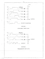
Page 9: ...16 I J I 0 3 li6 I 0 16 U 0 OUTPUT _____ 5 j 16 I 0 OUTPUT WAVEFORM FIGURE 1 FIVE INPUT HAND GATE 16 Ul INPUTS 0 y J 1 I i I I i tl6 0 n__2 l 4 16 0 n 3 1 OUTPUT 16 1 11JLJ 0 L_ I OUTPUT FIGURE 2 THREE INPUT IORTI GATE p Ie c ...

Page 10: ...n synchronism with the stepper switch This is accomplished with another five input II AND I gate This is essentially the same as having a permanent 23rd push button which when activated applies a pulse to the two shot reset generator This generator has two outputs one sli htly longer in duration than the other The longer of the two outputs is applied to t he binary divider to return each state to ...

Page 11: ...hen a tone of the proper frequency is present a voltage is obtained to operate a relay driver arnolifier In the case of the 1720 Hz COJ JTROL tone a pulsing and reset rel are emDloved such that short interruptions of the 1720 Hz Signal causes only the oulsing relay to operate This causes the stepper switch to advance one position _When a longer pulse interruption occurs such as generated by the tw...

Page 12: ... binary di vider c a1n is being pulsed by turning on the red lamp on the front penel of the Studio Control Unit hls relay is elsa connected with the telemetering indication relay so that a green panel lamp will turn on after the hinary lo ic is solved and telemeterlng si nal is present The telemetering detector and relay driver sta e are located on Board D Should the telemete l 1b tone stop t e rc...

Page 13: ... feedback for stability Schematic Drawln 913 6130 shows the power supply relays filters and interconnection between the two printed circuit sockets located on the ransmltter Control Unit It should be no ed that transistors operating aa amplifiers oscillators or detectors employ a small capacitor between the base and emitter to eliminate their suscep tibility to transient or stray R fields Maintena...

Page 14: ... necessary to modify the jumper wiring on the two terminal strips mounted on the rear 0f the stepper switch assemb y here are 21 individual terminals on each strip Access to these terminals can be obtained by removing the dust cover over the push button assembly When viewing the Studio Control Unit from the rear the top row of terminals carries the telemeterlnS si nals and the lower row carries th...

Page 15: ...1stors Q6l0 and Q6l1 compri e the basic circ it e collector of Q6l0 1s coupled through a clamp diode CR609 to the base of 0605 the telemetering output emitta follower When the a arm circuit 15 activated the base of Q605 is forced to near ground potential by virtue of its connec icn to 0610 Thus the telemeteri signal is momentarily reduced to zero when 0610 is conducting When this occurs the teleme...

Page 16: ...d by these jacks have a mlnlature hone plug attached to the cable supplied with the kit Attach the phone plug to either of these power jacks and attach the remaining wire to the selected telemetry input terminal As a specific example the Model TSK l Temperature Sensing Kit may be used with t e temperature reading being selected for instance on telemetry position 10 Simply plug the miniature phone ...

Page 17: ...ontrol fonel I C 1tG _ _LOJg TI Jo Inpnt I OR Sum r ing mplificr 1 1 8 1 liz Oscil lrltor P 1isc _____ l r LOCi pass L Schmitt Trigger I Telemeter l mpllfier RE I It Jt J _ _ _ _ _ _ _ _ _ _ _ a o _ __ To line Trunsfor7 er hen control Inc meterinc is by IllctDllic line To 5ubcnrriel gen rator when control nd metering is by P lld 10 Link from 1i ne t r lln s fo rr er Til en control Jnd metering is ...

Page 18: ...t ro 1 Rc 1ely Coil 1_ CiJ libr te Source I LOt cr Rel IY l I I I C ltLbratl l p 0 0 I Il l 2 I I I 0 I __ K l I I I l lC o 0 0 o Positions 1 t h rll 2 1 LC Jer Outputs by ROr OLink I From lin tran8fol Tl cr hen ont ro t and eter 1s by ruetnllic line I I l wi I 0 l l 0 I Rel 1Y Roise l J 1i5C Driver RE lay I I Det eeL 0 r mp lif ier I U t u fL lise ut put s 3 From Sub cclrrier detector uhen cor tr...

Page 19: ... 0r 1 1 IJ J 1 r I If r 1j c J l t L t l 1 I J I I C J t J ty I Ij N n t oJ c _ 0 rr r ul t J 6 9 0 f z Z If t 0 A i r U h It II U It 0 rr 0 1 r r z II 1 r r I I r CLJ 0 t ri _ CJ l J v l I V I J t 0 I i ...

Page 20: ... Vk S I 1 I _ L 1 i F_ T t IV k i C i _ I c v 1 1 I ______n I L _ o i L P t l JH JW I Ip I _ _____L ___________________________ p l _7_ 1 _ __ ___ C t A lu TF P rJ 2 5A _ IT Jr_ J JN5 E1 1 0 FHh r Ci Pf_ U I J 1 L I v J Or PC6 f V y FII V i I R 0 I R I I I w l iVLJ5ELEI R5SDC J 7 3 SR vlh BL IlJ P C j ____7 ...

Page 21: ... N b 4 1 l I F G t r v I I LCo I H I e C 6 LA L CK E T Lt CC A r 7 D 2 I j l I u c c I cr 11 tf rr _J Z l r BL I I N 5 __ 1 o 9 _ b 1 09 0 01 1 0 0 co vl n VI e l e l v IT t r r I hI K T U r_ C I F IH J L l 1 r r t l r II j r f 1 I JI r i 1M MOSELEY ASSOCIATE S ING A SA NTA UlR ARA CALIFOR NIA METER PANEL WIRING DIAGRAM MODEL PBR 21A PANEL 1077 b OINN X y 8 67 91A 6131 CI K ...

Page 22: ...1t5 1 002 D OOE 3 6 KEM1Tic 918 2 2 I ct THIS DWc 5VPe R E DE DWG 2 AIlS5 s r f I I r 10 7 I lO Ul N 8 aIODE I of J I I l 3 0 r U Q 0 0 0 v u w J I0 d r J c j t Y r UI C MOSELEY ASSOCIATES INC 1J c J 0 x IIANT IAR lA C L IP OANIA t oJ COMPONENT LAYOUT q PC BOARO A PBR 21 A SCU T r 8 z TOL FRAC r t 1 32 xx 030 XXX U10 0 r OWN F XY 11 61 SCAL I U LL cr 7 n lCHI VF lIlt ll I 20A 2055 a ENG J to 7 ...

Page 23: ...NTS AItE 11 J41S4 IOOE C 5CHEM4TlC 91e 6123 3 TI HS DJ r l P R se OES OWe 2Al15 J I W I a 1 1 lor lf J 1 J t _ _ 2 f old qrJ W r r y j IOSELEY AS O IATESf C SANTA IIARII R CALIr o NU COMPONENT LAYOUT II PCB a A ROB P B R 2 1A S CU lOl FH I C r 1 3 2 XX L 030 XXX no J o Dvm xv 111 f I C I L O lILL I tl j CHf I Tf_1 t J l1 c I 20 A 2 0 56 II ENG r II I r L r lI j r ...

Page 24: ...LU ARE IN CROF ARA TRi N 15TORS ARE 2N2 S24 2 5 C IH e MAT 1c I B 012 3 THa 5 DWG SUPERSEDE S DW 2AI157 1 UJ u oj u c I 1 1 r o c Z o 0 iii UJ a MOSELEY A SSO CIATES IN C e TA J I RBAFI C Ll O RN A COMPONENT LAYOUT PC BOARD C PBR 21 A 5CU lOL fRAC T 1 3 Y X OJI xxx 010 OWN 1 X Y I I G 71 SCALE 1 U L L CHK I f j F I I I i 2 0 A 205 7 ENG I I L 7 IA ...

Page 25: ...OFARAD I TRAN l rORS ARE Z N2924 NlJ W18 REO COWIPONE N T5 ARE 0 2 DIODE 5 Z SCHEMATIC 9166125 I 3 U5 AUDIBLE WlOD1F lC ATtON 5KA6l52 4 TI us I OVIIG SU E RS D S OWe AI15B 5 N DE NOTI S co roloJE NT C HAI I ES FOR SOB AUOIBLE 9 c 9 1 0 ___ of j 0 w Ci II ILl 3 If rJ o w 0 0 a j w 0 v en lLJ f MOSELEY ASSOCIATES INC 0 SANT A lIARII CA1 OllNIA COMPONENT LAYOUT PC BOARD D PBR 2IA SCU fJ z TOL f Rtl C...

Page 26: ...E 2N Jc I NOM EREO C OWlPONENT5 ARt lODe DIODES GHe MATIG 9186 26 I T r DW VPERSEDE 2AI 59 i f g c tO Ih Ldf ci uJ lJJ 0 0 0 cO Q J 1 oJ ad 0 1 fi t j I _ LlJ 0 J z Q If w cc t 0 r l VIj MOSELEY ASSOCIATES INO NTo A I I RA CAI IP o rA COMPONENT LAYOUT PC BOARD E PBR 21 A TCU TOL FflACT 1 32 XX 030 xxx U1O OWN F XV 1 10 SCALE FULL CHI 11 Ir 1111 1 20 A 2059 18 ENd J jI 1 7 I ...

Page 27: ...M CROf AR S i RAI l 5 TOFl ARE 2 2 9 C 2 t C TS RE N I S f r 1 Ll ll f a v J u J IJ If a3 co iDiii d ctN t Q o 0 l OU I _ _ 3 TH DWC3 SUPER S OES DW 2 A IOO 1 c 4 OEl lOTe CO PO e t 1T CHA G S FOR t P AUO ME i J I d I 0 1 CD ll I u I I J f f i h r I dJ D J ll a t l Z J 9 fJ A C L 1 1 MOSEU YASSO IA E I W NTA RIlAR cAL P ORN COMPONENT LAYOUT PC BOARD F PBR 2IA TCU 030 x 1 1 0 SCALE U L ENG I 20 A 2...

Page 28: ...I I I rl I i I I j i _ L TE lt INPUT I 2 III 17 6 15 4 13 J Jo II 1 1 Po TO MLTER 4 I LlGHrS I I 1 I I I II I I I I I I I _ _ L I I j I I i i I I i jj r l i r r or t r r t r i r r r I L __ _J _ 2 3 _ _ L I I r i _ L__ L_ __ ___ L LI_ __ _ _ J __ _ 1_ _ 1 _ 1 __1 I I _ _ l I _ j __J __ J SWITCfli 5 5HOWN ARE MECHANICAllY GANG E 0 ARE TWO OF A TOTAL OF EIGHT C HJTA C TS Tf IAT CLOSE EAC H TIME THEIR...

Page 29: ... Z C C1 Z 0 Z f e to t wP l T l O f A L c Z z z r I ii ...

Page 30: ... o I I O L _ ____ 1 ___ p 1 1 0 11 WIH r AI u N lMlfo ZOC I 4 c LO fJei AN 17Z0 I 4L H OTCr l IN 40 114 J C AM PlE RI31 jK C 1t 8 Ih I f IS l I O bl 5TATE GATE CONTROL 1720Hz CON1T OlC ATE 1 1 ni l 1 R 33 Il l i lOOK K r nu CW 1 3 n 1 AI l l y i III 4 100 K 40 fq 11 CI III LI I 2 HPj 21 1 1 39 3 3K U c U II Unf l 0 AT lOC v Tr WljlL TrMI SG C l I c mr YP 12 0 e I Ct Nlll ojVOUS wtH N W U M l io If...

Page 31: ...jl Ll ll _ _ I I J INA Y F LlP I LCP H b INAJ Y r l p F LOP t biNARY FI IP f LOP 5 co 2 Q Ift U ___J 1 I r L N O f Oi C INLE SS O I ERW I E I E c I F IEO HI I r n Y L I A E 1N jM I L lO C P L ITOO V o L U e A l IN M C H FA P A D 5 l AN r R AS Z N 9l 4 I O ICD Ii A I I N I I fIiC A iJ J Ot I o Tq N I ro J Qr K E 1 fT VI E W N r TC 2 t 2 9 4 I M f l vae rt QvOc CA 2 n t c 2 2r _ 11 2 2 4 l Vc I lL I...

Page 32: ...31 0 l Z VV v I I I _ I I J_ c I i 2 2 II I I I C N NE r 1 r c Iv 1 S Te p o u riJU r I I H C ll TRe l T NE Ck O _0 D rR I 15 T j H c I C T 1 ep VIE W L OW E H 1 2 00 Hz A lv l 1 _ __ _ __ _____ _ __ _ __ _ __ __ __ __ ____ ____ _ _ ___ _ ____ ___ I 1 1 A SI TU N2 TO l P it H32G T Es r I I IT II I i 2 K I l 1 1 r J E l Q 05 1J cmq rc g lllr G HD _ 3 T 1 0 C 17 _ 11 l S r 21 1 __ r O j j 1 C OI fI ...

Page 33: ...I i t J llJ s o Cll T 6 sc p OT rtn w I I V _ _ I c f C _ j t V _1 l l Ll II VVv 01 o I I _ I M I I I A l I rl l l l l b t c it l I 4CL c t t I O Y J M E c tJ I 1 r t l O 1 2 1 J 0i Mrl v U ll T I n o I 1 2 1 1 I l r n 1 J L r t C t l H L r t z 9 Ivv f J 0 0 CI T PU T TD CA L I f A H J R r 1 h u J t v F n E VI i H I B 1 l n r I li t Llt H t f 1 t w c I fC vr _ o 1 N M t J 1 1 2 c c I To v i I E t ...

Page 34: ..._ C O N T u l_ _C_ RCU _ I T ______ _ L502 1 IHY C511 3S0 111 0 1 I 1 519 Q 50 DPlv cn H TP 15 1 120 Hz _ 1 Ui E l AMP FI E P TeST P0 1NT i I LOCAL I JNT ROL 1 0Sf f PEIl PU5HBUTTON w t rl_ j_ G Tur M ce 1 1 2 ilb cnS0 5 0 1 Of r 5I J L It R5 2 7 t U 7 p x u 1 V Ar A or _r l _ JW J IN FkC M liMITIN0 UNEAMP F 10 1 51t I I 00 111 03 r 13 J K c I OO I l z TUN I I I OJ I 5 1 LOWER G CAM PLIFIER 10 _ _...

Page 35: ... 1 CRE A5 E ONlI fO E JSIT IV ry by AY 1 O cl de AOO O p 1 0 1 L TH t v N I f1 OA20 60 f N O r t 5 U N L S O T kEi l W I l 5PE 1 1 l O I E I S T R l L J A I N O t1i I I a 1 O c AD_e I Tcn VALUt C Q I N M IC O YF Ao AD So T Q t r S I 5Tc QS l IL 2 N29 2 y t V T O C Ot liC OL 1uN uTP J U l lFI E H OI O F S A AE IN i4 U I OE L l f I O C J lJQN N y VAI e s A RE Of 2 _ 0 C IC R h DI O I N K rt L l TE I...

Page 36: ...ri 2 N C t H waE T R I t f iN 1 N t BNC P U H Id lT ON I H C SE E DWG6 k 6 1 j 5 1 i ol 1 1 1 11 1 1 ONT 1 1 0 j DOt U E ON l N l E N J I N 0 MET E n A N C 2 MET e R AN L h OlV Oll I O o 7 fiU H f N 7j To 50 0 0 _ __ _ _ _ 0 _ _I _ 100 I C O A 1 0 D P N C M T bN F OP Q A OI C UN l OIH T 02 NC 1 I N fALI C 0 b r of L III PIN S O C E T Y ______ L___________ P I N hJC f r N ll OP L AT IOUA 1 A I OD a...

Page 37: ... rE IN OJ W l r _ 0 1 I 2 2 pL a J 7 SbO 2 ShOI 151 1 I T r I 1 t lGIQAo 1 1 1 WII _ T I IC 2 I lO J r 9 l r E OLL I o _ t A Llt 1 M T J f t lC C c M r _ NT 6 I _ _ _ J V L I A AL 1 j 0 I I l jI I tLI I 7 0 1 ow Ol I c 0 t c 2 o 11 oa H J GALIb 1 00 0 F I t H I01 it UI __ _ I y__ J J J I U lS f r y O l I 0 ill 11 011 b 41 D I I wn z c Uti I l r Iu 1 0 I O u 0 11 0 Ii t W I L O W I 1 1 o I IIl H I ...

Reviews: