background image

~1~ 

PREFACE 


This manual offers all service specialists with the technological 

procedures of maintenance, repairing for  PA125


detailedly show 

those whom may concern how to maintain, repair, change parts, 
troubleshoot and reassemble, etc. 
    At every important section we illustrate by assembly, explosion 
diagrams and photographs, if necessary, please check the diagrams 
already shown. 
    Though we have tried our best, please kindly instruct us any 
faults found in this manual. 


MOTIVE POWER INDUSTRY CO., LTD. 

Summary of Contents for PA125

Page 1: ...e whom may concern how to maintain repair change parts troubleshoot and reassemble etc At every important section we illustrate by assembly explosion diagrams and photographs if necessary please check the diagrams already shown Though we have tried our best please kindly instruct us any faults found in this manual MOTIVE POWER INDUSTRY CO LTD ...

Page 2: ...n timing 28 10 Idle Adjustment 29 11 Front brake adjustment 29 12 Rear brake adjustment 30 13 Tire 30 14 Throttle cables adjustment 31 4 Dismantling maintaining repairing and assembling operation 32 1 Lubrication system 33 2 Plastic parts of chassis 37 3 Engine dismantling 42 4 Drive pulley starter clutch driven pulley 44 5 Cylinder head and valve 53 6 Cylinder and piston 58 7 AC generator flywhee...

Page 3: ... 3 5 Electric equipment 95 1 Troubleshooting 96 2 Battery 97 3 Recharge system 99 4 Ignition system 101 5 Starting system 103 6 Starting clutch 105 7 Handle bar switch 107 ...

Page 4: ...ht 211kg front 1 50kg cm2 Front 62kg rear 1 75kg cm2 Rear 149kg ŸBrake ŸPerformance front 190mm hydraulic Fuelconsumption 42km L disk brake rear drum brake ŸGradient ability 22 ŸSpeedometer 130km hr ŸEngine ŸLamp Model C2 front 12V 35W 30W 1 Fuel unleaded or leaded Cooling system forced air cooling by fan license plate 12V 5WX1 brake lamp 12v 21W 5W X 1 Cylinder signal lamp 12V 10W X 4 bore 51 5mm...

Page 5: ...9 a For engine b For chassis c Wheel bearing 12 4 Wiring diagram 13 5 Troubleshooting 1 Hard starting or no starting 2 Not smooth rotation weak acceleration inefficient horse 3 Engine running not smoothly low speed 4 Engine running not smoothly high speed 5 Charging abnormal battery over charging or over discharging 6 No Sparking spark plug ...

Page 6: ...antling please wash all parts necessary for checking and grease all contact surface when reassembling 5 Use grease recommended by P G O 6 When removing battery please dismantle the negative pole first when assembling please connect positive pole first 6 Before installing a new fuse confirm the specification is correct or not 7 After reassembling please re check that all connecting point locking pa...

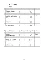
Page 7: ...1 12 5 0 6 0 11 Spark plug 1 10 1 2 1 3 12 Nut drive clutch 1 22 9 0 10 0 Left thread 13 Screw inner chain adjuster 1 6 0 4 0 6 2 Chassis NO Locking location Q TY Thread dia mm Locking torque kg m Remark 1 Locking nut steering stem 1 10 4 5 2 Front axle nut 1 12 4 5 5 5 U type nut 3 Rear axle nut 1 16 11 13 U type nut 4 Rear shock absorber bolt upper 1 10 4 0 5 Rear shock absorber bolt lower 1 8 2...

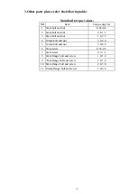
Page 8: ...nut 0 45 0 6 2 6mm bolt and nut 0 8 1 2 3 8mm bolt and nut 1 8 2 5 4 10mm bolt and nut 3 4 4 0 5 12mm bolt and nut 5 0 6 0 6 5mm screw 0 35 0 5 7 6mm screw 0 7 1 1 8 6mm flange bolt and screw 1 0 1 4 9 7mm flange bolt and screw 1 0 1 4 10 8mm flange bolt and screw 2 0 3 0 11 10mm flange bolt and screw 3 0 4 0 ...

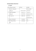
Page 9: ...rt sliding part premium 4 stroke Auto separated Lubrication 2 cylinder rotating part sliding part motorcycle oil or SAE15W40 Total 900 c c Replacement 800c c 3 drive gear box SAE85 140 Total 110 c c Replacement 90c c 4 gasket of starter shaft clean grease 3 5 start idle gear sliding parts clean grease 3 ...

Page 10: ... 10 B CHASSIS Steel ball steering Front brake fluid Front brake cam ...

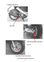
Page 11: ... 11 C WHEEL BEARING Motor oil Final transmission mechanism gear oil Speedometer gear clean grease Front wheel bearing clean grease ...

Page 12: ......

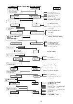
Page 13: ...ing bad action of auto choke air trapped in intake manifold ƒwrong ignition timing bad adjustment of carburetor s fuel adjusting screw carburetor fuel leveltoo high malfunction of auto choke ƒthrottle valve open too largely Check and adjust Trouble condition The reason The fuel supplies carburetor enough or smooth loosen carburetor draining screw check if inside of carburetor have fuel or not No f...

Page 14: ...ng is too early too much carbon in the combustion room bad quality of the fuel ƒclutch slip mixture is too lean ignition timing is too early Check and Adjust Trouble condition The reason start engine and open throttle gradually check and inspect engine can rotate up engine can t rot ate up completely Check ignition timing check with ignition timing lamp Timing is correct Timing is not correct bad ...

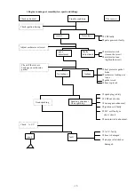
Page 15: ...DI out of order ƒAc magneto abnormal ignition coil faulty H T coil faulty or short circuit main switch is abnormal A C V faulty hose is damaged ƒair pipe is blocked or damaged Check and adjust Trouble condition The reason Check ignition timing Adjust carburetor oil screw good adjustment faulty adjustment Check if there is air Leakage on carburetor gasket No leakage leakage Good sparking Sparking a...

Page 16: ...nd wash it the mark of cam s timing gear does not align Spring faulty Check and adjust Trouble condition The reason Check ignition timing Adjust valve gap correct Not correct Check auto cock Fuel supply system good unsmoothly Check carburetor Is blocked or not No blocked blocked Check valve timing correct Not correct Check the valve s Reverse spring good Spring broke or fatigue not correct correct...

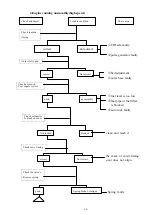
Page 17: ...then start engine Voltage remain The Same Voltage goes up To normal value But after engine Stop the Voltage Goes down again Check voltage rectifier Plug is loose or not good loose Check the voltage Between chassis Θand The red cable of Voltage rectifier Check the resistivity Of A C generator coil normal abnormal Start engine connect Green cable to Chassis then measure The voltage between Chassis Θ...

Page 18: ...e ignition coil Check and adjust Trouble condition The reason Replace new spark Plug then check again Good sparking Weak sparking Or no sparking Check spark plug cap And H V cable is Loosen or not good loose Check the CDI plug Is loosen or not good loose Check the connection Between CDI Plug and Each terminals check The resistivity of Each terminals good abnormal Check relative parts good abnormal...

Page 19: ...le 2 Battery 3 Clean air cleaner 4 Oil screen 5 The final reduction mechanism oil 6 Spark plug 7 Cylinder pressure 8 Valve clearance 9 Ignition timing 10 Idle adjustment 11 Front brake adjustment 12 Rear brake adjustment 13 Tire 14 Throttle cable adjustment ...

Page 20: ...olumn Brake lever b movement of brake Loose or damage brake Brake cables change per 2 years Brake cam Worn out a clearance between drum and plate b brake shoe and br ake plate worn out Brake drum And brake shoe c brake drum worn and damage Standard dia Rear 130 0mm Limit of use Rear 131mm mark type front axle dam age or cracked rear axle worn or damage Check rear Axle Wheel pressure Unit kg c ldri...

Page 21: ...ge Connecting part Loose Bracket loose or Damage Suspen sion Connecting Part loose Oil leakage Cracked Damper damper assy s part Loose Clutch and Change Speed mechanism Power Transmi Ssion Supply grease per 2 year Ignition Clearance 0 6 0 7mm NGK C7HSA OR SAME SPEC Start mechanis m Starting Motorpinion Meshing wiring Recharge Effect Electroly Te quantit Level between UPPER AND LOWER battery Electr...

Page 22: ...usting air Air cleaner Cylinder cyl inder head inlet Pipe locking Condition Locking torque Cylinder head cold 1 0 1 2kg m inlet pipeLcp d 1 0 1 2kg m Engine parts Compression pressure Using stating Motor 12kg c 750rpm Oil leakage Oil quantity Dirty Change every 1000kml Oil quantity Lubr icat Ion Syst em Oil filter Change every 5000km Fuel quantity Fuel leakage Carburetor Parts dirty Carburetor thr...

Page 23: ...Performance Lamp system Dirty cracked Horn turn Signal Reflector Performance Horn Turn signal lock Performance Rear view mirror Check the illumination Blinker linc Nese plate nu Mber mark Dirty cracked Instrument board performance Ass y part Loose cracked Muffler silencer performance chassis loose or cracked The earlier Abnormal condition Confirm it does Not happen again Chassis Lubrication others...

Page 24: ...he negative cable and then the positive cable take out the battery to recharge 4 Re assembling the battery as the opposite procedure of disassembling after recharging Note A Do not take out the sealed bolt when recharging B Without refilling water for the battery Please recharging 12V as the following current Time standard 0 7A 5 10Hr or Rapid 3A 1Hr ...

Page 25: ... remove the oil meter Oil meter 2 Screw out the oil draining bolt on the bottom Torque 1 5kg m Engine oil volume Disassembling 0 90 liter Exchanging 0 80 0 85liter When checking the leakage of oil start the engine At idling for a few minutes then check the oil volume Lower limit Attn Do not start engine when air cleaner is not installed Note A The vehicle must park on the flat ground Before checki...

Page 26: ...g 0 ring and the Oil draining bolt Locking torgue 1 5kg m 2 Second oil filter l Replace it per 5 000km l Torque 8 0 2 N M 5 The final reducing mechanism oil 1 Change the oil in the gear box a Turn off the engine after warm up b Put a bowl under the engine c Remove the draining bolt and filling bolt to drain the gear oil off d Lock the draining bolt before refill 110c c gear oil and then lock the f...

Page 27: ...ngine is warm 2 Remove the cover at the right hand of the step floor 3 Remove the spark plug then place cylinder pressure gauge Then fully open the throttle and act on the starter motor to measure the compression pressure Compression pressure 12kg cm2 at 750 rpm When the compression pressure is too low check the following a Valve leakage or not b Valve clearance c Gasket of the cylinder head is da...

Page 28: ...ng light to assure the ignition timing is correct 3 Under idling it means in good function when crankcase s mark matches to the F on the flywheel 4 Raise the engine revolution to 5000 rpm slowly it means in good function if the crankcase s mark matches with Entering point of the flywheel Note Checking and adjustment of valve clearance only can be done under 35o C of engine temperature Note There i...

Page 29: ...system is leaking 3 Check the oil level a Refill the brake oil when the level is under the LOWER line b Oil specification SAE J 1703 or DOT3 orDOT4 Note a To prevent the oil splitting onto the parts or clothes put a piece of clothon the bottom when refilling b Be caution not to mix water or particles into the master cylinder when refilling c Never use the oil that is not complied with spec d In ca...

Page 30: ...e when it is too low The pressure is according to the carrier driver passenger accessories and cruise speed 2 Proper loading is very important for steering riding braking performance and safety Never carry any parcel unfastened Load the heaviest parcel on the center of vehicle balancing the weight on both sides Beware of the weight loaded properly and check the tire pressure The total weight of ca...

Page 31: ...stripe lDepth front and rear According to the mark of tire indicating the necessity to change a new tire 14 Throttle cables Adjustment 1 Check the clearance of throttle 2 Normal clearance 1 5 3 5mm Adjust it by rotating the adjust nut Change it if the throttle cables can t be adjusted ...

Page 32: ...hassis 3 Engine dismantling 4 Drive pulley starter clutch driven pulley 5 Cylinder head and valve 6 Cylinder and piston 7 AC generator 8 Final transmission mechanism 9 Crankcase crank shaft 10 Carburetor 11 Steering stem front wheel frt brake comp frt fork 12 Rear wheel rear brake rear damper 13 Fuel tank ...

Page 33: ...33 1 Lubrication System Lubrication System Diagram ...

Page 34: ...ffler 2 Remove the AC flywheel magneto 3 Remove the AC generator coil 4 Tale off the locking bolts of the right crankcase cover 5 Remove the crankcase cover 6 Remove the washer lock pin 7 Remove starter reduction gear and the starting clutch ...

Page 35: ... 3 Install the lock pin 4 Match the lock pin hole to the pump cover and install the oil pump cover 5 Put on the screws and tighten them 6 After installing turn the shaft lightly to assure installation 7 Place the oil pump into the carnkcase 8 Tighten the oil pump after installation Note The notch of the oil pump shaft should comply With the notch of the inner gear Note When installing the arrow on...

Page 36: ...y 0 045 0 10 0 12 Oil pump Clearance between gear end and Oil pump body 0 045 0 10 0 12 Troubleshooting Reduction in fuel oil volume Engine burning out a Natural consumption a Zero or too low oil pressure b Leakage of fuel b Blockage in oil route c Piston loop seizes or improperly install c Did not use the fuel oil recommended ation d Worn out of valve s oil seal ...

Page 37: ...rts 1 Removal of luggage compartment l Open the seat take off the screws of the luggage compartment 2 Removal of fuel tank l Open the lock cover of the fuel tank lTake off the fuel tank cover lTake off both the right and left handles by removing the screws off ...

Page 38: ...f left and right hand Side covers lTake off the screws of left and right side covers lRemove the left and right hand side cover 4 Removal of front mudguard lRemove the screws of front fender lTake off the front mudguard ...

Page 39: ...B Dismantling the Fender 1 Take off the screws of front inner cover And fender 2 Take off the screws between the front Fender and chassis 3 Separate the head light and signal lamp Cable 4 Take off the fender ...

Page 40: ...antling the upper handle cover 1 Remove the left and right Back mirror 2 Remove the screws of upper And lower handle cover 3 Unplug the speedometer cable 4 Unplug each switch cables 5 Remove the upper handle cover ...

Page 41: ...and front inner cover 1 screwing out the screws of battery cover 2 Disconnect the negative then positive cable 3 Screwing out the screws between the step floor and front inner cover Take off the front inner cover 4 Pull out both the negative and Positive battery cables Take off The step floor 5 When assembling the procedures Will be reversed M6 0 7 1 1kgf m M5 0 35 0 5kgf m Note Avoid clamping and...

Page 42: ...42 42 2 Engine dismantling A Dismantling engine B lnstalling engine ...

Page 43: ...le carburetor pipe engine suspension nut starter motor cable flywheel plate and rear damper bolt 5 Remove the engine B Installing Engine 1 To install engine please reverse the Above procedures 2 Locking torque M8 2 0 3 0kgf m M10 3 0 4 0kgf m M12 5 0 6 0kgf m 3 After installing pleas do the following Checking and adjustment a Wiring for each circuit b Throttle cable c Rear brake adjustment d fuel ...

Page 44: ...44 1 Drive pulley starter clutch driven pulley A troubleshooting B Measurement data C Driving pulley D Starter E Clutch driven pulley ...

Page 45: ...ty Note No grease and oil should be distributed over driving belt and driving plate B2 Measurement data for PA125 Item Standard value mm Limit of use mm The inner dia Of slide driving plate 24 011 24 052 24 10 The outer dia Of boss movable Driving plate 23 96 23 974 23 94 Belt width 20 0 21 0 19 0 Clutch lining thickness 3 1 5 Clutch lining thickness 125 0 125 2 125 5 Driven plate spring free leng...

Page 46: ...y 1 Take off the screws of Left cover Remove the left cover 2 Remove the lock nuts of driving Plate and the nuts of Starter gear And clutch 3 Take off the ramp plate Belt and clutch 4 Take off the boss and driving plate ...

Page 47: ...crease the engine s speed slowly and notice the RPM at which the motorcycle begins to move forward Specified Engagement RPM 3800 300 rpm 5 Clutch LOCK UP inspection l Apply the rear brake as firm as possible l Briefly open the throttle fully and notice the maximum engine RPM sustained during the test cycle Specified Clutch LOCK UP RPM 5100 400 rpm ...

Page 48: ...ing belt width change it below using limit 7 Disassemble slide driving plate set 1 Remove bush of slide driving plate 2 Remove screw and disassemble the cover of slide driving plate 3 Remove ramp plate 4 Remove weight roller 8 Checlomg 1 Check the wearing condition of weight roller change it below when below using limit Locking torque 1 Nut of driving pulley M10 4 0 5 5kg m 2 Locking nut of clutch...

Page 49: ...on 4 Check the outer diameter of the contact surface of the movable driving plate limit of use change it below using limit 9 Assemble the slide driving plate 1 Clean up the inside surface of slide driving plate then assemble the roller 2 Assemble the ramp plate 3 Other procedure refers to the opposite procedure of disassembling ...

Page 50: ...Check the wearing condition of the outer diameter of spindle comp and the inner diameter of bush and gear b Check the wearing conditionof shaft of driven gear comp Gear sets and ratchet 9 Assembling the starter Assemble the starter follows the Opposite procedure of dismantling Locking torque M6 1 0 1 2kg m Note Make sure one end of the torsion spring is hooked on the groove of driven gear and anot...

Page 51: ...emble the clutch follows the opposite procedure of dismantling 3 Checking clutch dismantling tool a Check clutch driving face Check clutch cover about its wearing condition And inner diameter measurement l change it above using limit b Check clutch lining wearing condition and Measure the lining thickness llimit of use change it below 1 5mm Locking torque M10 4 0 5 5kg m ...

Page 52: ...condition of driving plate sets And measure outer diameter llimit of use change it above 33 95mm e Check wearing condition of slide driven plate And measure its Inner diameter llimit of use change it above 34 00mm f Check is there any wearing occur to the ditch g Check wearing condition of oil seal if necessary change a new one ...

Page 53: ...53 5 Cylinder head and valve A Trouble shooting B The operation data information C Dismantling and installing ...

Page 54: ...ressure is too high There is too much carbon accumulated in the combustion chamber 4 There is white fume coming out from the exhaust pipe The valve stem or valve guide pipe is worn out Valve stem s oil seal is damaged B The operation data information Description IN EX Standard Value mm Limit of use mm IN 0 08 Clearance between adjuster tapped Screw and valve stem Before warm up EX 0 08 Compression...

Page 55: ... cover and take off the cylinder head cover 4 Turn the flywheel counterclockwise and let the T mark on the flywheel point to the crankcase mark and make the round hole on the cam chain gear point upwards This is the upper dead point of compression 5 Take off the cam shaft holder the nut and the locking pin 6 Remove the cam gear from the cam chain 7 Remove the cam shaft ...

Page 56: ...concave points and the cylinder head are at parallel position convex part of cam shaft points upwards then install the cam shaft on the cylinder head 3 Install the cam chain onto the cam shaft gear 4 Install the locking pin 5 Install the camshaft holder washer and nuts on the cylinder head 6 Lock tightly the cylinder head nuts Locking torque Cam shaft holder nuts 2 0kg m 7 Adjust the valves cleara...

Page 57: ...d gasket 8 Remove cam chain guide Further dismantling lUse the valve contracting tool to remove valve pin supporter the vlave spring collar valve spring and valve stem oil seal Notice lNot to injure the contact Surface of the cylinder lAvoid any object dropping info the engine Notice lValve Spring has to be operated by the valve spring contractor lTo assemble the cylinder head please follow the op...

Page 58: ... 58 6 Cylinder and piston A Trouble shooting B The Operation notice C Data D Dismaniling cylinder piston E Installing cylinder piston ...

Page 59: ... of gasket must be clean 3 Dismantle cylinder and cylinder head by screw driver Do not injure the contact surface 4 Cylinder inner surface and piston outer face can t be injured Contact Surface should lubricate by specified oil C Data Part name description Standard value mm Limit of use mm Bore 51 490 51 510 51 60 Curve 0 05 Cylindrility 0 05 Cylinder Roundness 0 05 lst ring 0 03 0 07 0 10 Clearan...

Page 60: ...the piston ring c PISTON OUTER DIA MEASUREMENT 1 Measuring location Perpendicular to the piston pin hole down to 7mm form the piston skirt 2 The clearance between the piston and piston pin 3 Checking any wearing damage inside the cylinder Vertical to piston pin and in X Y direction to measure cylinder bore from the upper middle and lower location 4 The maximum clearance between the cylinder and pi...

Page 61: ...nd lower position of the inner dia in X or Y direction d Checking the flatness of cylindercontact surface e Connecting rod small end inner diameter measurement Limit of use Roundness change it when above 0 05mm Cylindrility change it when above 0 05mm Limit of use change it when above 0 05mm Limit of use change a new one when above 13 06mm ...

Page 62: ...piston piston pin and piston pin clip b Installing piston 1 Fix the lock pin and gasket on the crankcase 2 Lubricate the Cylinder inner surface piston and piston rings by Motor Oil 3 Install the piston ring into the cylinder carefully NOTICE Do not drop other objects into the crankcase NOTICE a The mark IN on the piston tip should face to the INLET side b Do not drop the piston pin clip into the c...

Page 63: ... 63 7 A C Generator A Dismantling AC generator B Installing AC generator ...

Page 64: ...ing AC generator 1 Rimove fan cowl 2 Remove the M6 screws 3 Remove screws of flywheel magneto 4 Remove the AC flywheel magneto by special tool 5 Remove the flywheel 6 Remove the electric plug of AC flywheel magneto ...

Page 65: ... 65 B Installing AC generator To install please reverse the dismantling procedure Locking torque M6 1 0 1 2kg m M10 3 2 4 0kg m ...

Page 66: ...smission mechanism D Assemble the final transmission mechanism A Troubleshooting lEngine can be started but the vehicle doesn t move 1 Gear worn out or cracked 2 Gear burnt out lNoise occur when running 1 Gear worn out burnt or gear surface 2 Bearing worn out of loosen lOil leakage 1 Too much oil 2 Seal worn out or damaged ...

Page 67: ... 67 3 B Disassemble the final transmission mechanism 1 Remove the rear wheel 2 Drain the oil in the gear box 3 Remove the bolt in the gear box cover Take off the gear box ...

Page 68: ... 68 4 Remove the final reduction gear And idle gear 5 Clean up the gear box C Check the final transmission mechanism 1 Check the wearing condition of driving shaft and gears ...

Page 69: ... final reduction gear 4 Check the wearing condition of the oil seal and bearing D Assemble the final transmission mechanism please follow the opposite procedure Of disassembling After locking the drain bolt refill 110cc of gear oil SAE90 Locking torque M6 1 0 1 2kg M M10 3 5 4 0kg M Drain bolt M8 1 8kg M ...

Page 70: ... 70 9 Crankcase Crankshaft A Disassembling diagram B Troubleshooting C Data D Remove crankcase and crankshaft E Check crankshaft F Assemble the crankcase ...

Page 71: ... 71 A Disassembling diagram Torque 1 0 1 2kg m B Troubleshooting Engine noise 1 The bearing of final transmission mechanism is loosen 2 Crank pin of bearing is slack 3 The bearing of gear box is loosen ...

Page 72: ... end vertical direction 0 04 Swingness of the crank shaft journal 0 03 0 10 D Remove the crankcase and crankshaft by the following procedures 1 Remove the engine 2 Remove the muffler 3 The carburetor 4 Engine corer 5 Cylinder head 6 Cylinder 7 The driving plate 8 AC flywheel magneto 9 The starter clutch 10 Oil pump 11 Bolts of left right crankcase ...

Page 73: ... A B Change it when above 0 1mm Change it when above 0 1mm 3 Check the looseness of crankshaft bearing If it is loosen replace to a new one F Assemble crankcase 1 assemble crankcase according to the opposite procedure of disassembling 2 The locking torque of bolts and nuts are described in previous chapter please refer Limit of use replace it when above 0 04mm ...

Page 74: ...smantling the float and nozzle Carburetor Specifications ITEM SPECIFICATION Carburetor type KEIHIN CVK24 Bore size 24 mm I D NO 065 Idle r min 1700 100 Float height 17 0 0 5 mm Main jet 85 Jet needle NACB Needle jet P O Pilot jet 35 35 Pilot screw PRE OPENING 2 turns out ...

Page 75: ...the carburetor air cleaner blocked oil pipe blocked bad adjustment of the fuel level float valve is jell lMixed air too dilute 1 Main jet blocked 2 Float valve blocked 3 Fuel level too low 4 Fuel system blocked 5 Second air sucked into intake system 6 Bat vacuums during piston movement 7 Throttle valve malfunction ...

Page 76: ...uel system blocked 2 Ignition system malfunction 3 Air mixture is too dilute or too thick 4 Fuel deterioration 5 Second air sucked into intake system 6 Bad idle adjustment 7 Bad fuel volume adjustment 8 Idle system or auto chock system blocked 9 Bad adjustment of fuel level lMixture air too thick 1 Auto chock system malfunction 2 Float valve malfunction 3 Fuel level is too high 4 Air route blocked...

Page 77: ...t of fuel volume adjusting screws 1 After the engine is warm up adjust the stopping screw throttle of throttle valve to the standard rpm Idle rpm 1 700 100rpm 2 Adjust the fuel volume adjusting screws to the highest stable rotation This rotation value is the optimum setting of throttle 3 Fuel up for several times make sure that the idle rpm is within the standard rpm Repeat the above procedure if ...

Page 78: ...et main jet and fuel adjusting screws lAssemble the float valve float and float pin 4 Checking fuel level Note When the valve is too dirty or severely worn not the Valve base will not close completely thus will result In increasing of fuel level and fuel leakage problem A new replacement is needed Note lAvoid any damage on the jets and the fuel adjusting screws lBefore dismantling record the numbe...

Page 79: ... 79 11 Steering stem front wheel frt brake comp and front fork A Troubleshooting B Data C Steering handlebar E Front wheel F Front brake G Front fork ...

Page 80: ...t damper is not even b Front fork is crooked c The axle of front fork is crooked wheel is aslant 3 front wheel swings a wheel rim is distorted b bearing of front axle too free c wheel rib is distorted d Wheel is not good e Front wheel axle locked improperly 4 front damper is too soft spring fatigue 5 noise in front damper a noise comes from damper box b locking screw of damper is slackness B Data ...

Page 81: ...t of speedometer cable 3 Remove the front handle cover 4 Remove the fixed screws of speedometer cable on the right of front wheel 5 Draw out the damage speedometer cable 6 Assemble the new cable follows the opposite procedure of dismantling NOTE Put the grease onto the Inner cable before Assembling ...

Page 82: ...uts on front fork and handlebar 4 Take off the fixing bolt 5 Remove the nut and bolt of the front fork fixed on The handlebar 6 Take off the handle bar 7 When assembling please follow the opposite procedures 8 Before assembling please add grease on each cable Locking Torque M6 1 0 1 2kg m M10 3 0 4 0kg m ...

Page 83: ...ront wheel follows the opposite procedure of dismantling Locking Torque M10 3 0 4 0kg m Note 1 Put the lock block of speedometer gear assy upon the extrusion of the front fork 2 Put the grease onto the grease sets of speedometer before assembling 5 Checking the front wheel axle a Check the bending degree of the front axle b Take note of the bending degree on the middle of axle c Limit of use Chang...

Page 84: ...aring is Loosen or any occurrence for noise Please change a new one 7 Front wheel rim checking 1 Check the swing of the front wheel rim 2 Limit of use lHorizontal direction Change a new one when above 2 0mm lVertical direction Change a new one when above2 0mm ...

Page 85: ... the container b Do not let the brake oil overflow from the master cylinder or container when assemble the master cylinder cover c Put the spanner upon the drain screw d Lock and unlock the screw several times to Release the bubbles e Operate slowly the brake lever several times f Clamp the brake lever to the end g Loose the drain screw then open the lever completely h Locking the drain screw and ...

Page 86: ... Front shock absorber checking Check is there any unusual damage or worn out condition and whether the guide rod of the Front fork is crooked or not Front fork oil type SAE 10W20 Capacity each side 80 CC NOTE If the guide rod is crooked it should be replaced by a new one or repaired ...

Page 87: ...Assemble the disk follows the disassembling procedure Locking torque M8 2 0 3 0kgm 6 Checking the front brake disk Standard thickness of disk 3 6mm Limit of usage change it when below 3 1mm 7 Checking the front brake lining a standard thickness 4 0mm limit of use As the thickness is below 2 0mm change it Note No grease on the lining ...

Page 88: ... 88 12 Rear wheel rear brake rear damper A Troubleshooting B Data C Dismantling the rear wheel D Checking the rear wheel E Rear brake F Rear damper ...

Page 89: ... the adjustment of brake is not good b the brake lining is dirty c the brake lining is worn out d the cam of brake lining is worn out e the brake cam lever is worn out f the brake hub is worn out g the assembling of brake lever gear trough is not good B Data Item Standard value mm Limit of use mm The swings of rear wheel 2 0 Brake hub inner diameter 130 131 0 Thickness of brake lining 4 0 2 0 ...

Page 90: ... rear wheel drum 3 Remove the bolts 4 Remove the rear wheel 5 To assemble the rear wheel please reverse the dismantling procedures Locking torque M6 0 7 1 1kg m M14 8 0 10 0kg m D Checking the rear wheel lcheck the swings of rear wheel lradial direction change it as it is above 2 0mm lhorizontal direction change it as it is above 2 0mm ...

Page 91: ...Checking rear brake hub a measure the inner diameter of rear brake hub b limit of use change it as the diameter is above 131 0mm 2 Checking brake lining a measure the thickness of rear brake lining b Limit of use As the thickness is less than 2mm change it ...

Page 92: ... 92 F Rear damper 1 Rear damper disassembling diagram ...

Page 93: ...k over extended 2 The mixture is too lean a Ventilation hole is blocked b Fuel pipe is crooked squeezed or blocked c Auto cock and fuel filter is dirty B Dismantling and assembling Fuel Tank 1 Remove the luggage box 2 Open the rear cover of the fuel Tank and take it off 3 Remove the left and right rear handle bars 4 Remove the left and right side covers ...

Page 94: ...he connecting terminal of the fuel gauge 7 Remove the fuel gauge 8 Remove the fixing blot of the fuel tank 9 Take off the fuel tank 10 When re assembling please follow the opposite procedure of disassembling Locking torque M6 1 0 1 2kgf m ...

Page 95: ...charge system 2 check A C flywheel magneto 3 check regulator rectifier 4 Ignition system 1 the wiring of ignition 2 check spark plug 3 check H T Cable and H T coil 4 check C D I set 5 Starting system 1 the wiring of starting 2 checking the starter 3 dismantling the starting motor 4 checking the starting motor 6 Starting clutch 7 Handle bar switch ...

Page 96: ...dary wiring 1 Spark plug is abnormal Ignition coil is abnormal 2 Wire connects improperly broken or short Spark plug is abnormal Circuit ƒH T coil is abnormal between A C flywheel magneto and CDI Spark plug cover electricity leakage sets 3 Ignition period between CDI sets and H T coil A C magneto is abnormal ƒbetween CDI sets and main switch A C G coil disconnects between main switch and spark plu...

Page 97: ...ble of the recharger to the negative cable of the battery Recharging currency Please recharge 12V according to the following currency and time Standard 0 7A 5 10HR OR Rapid 3A 1Hr NOTICE 1 It is not necessary to refill the battery liquid into the battery 2 Do not take off the sealed bolt while recharging NOTE lNo fire near battery when recharging lThe ON or OFF of recharging currency must be opera...

Page 98: ...hite cable fuse d Set the headlamp switch at OFF engine rotation is at 2000 rpm while testing Then increase the rpm slowly Head Lamp Switch Recharging rpm 2 500rpm 6 000rpm OFF DAY Under2 000upm 0 6A MIN 1 5A MIN ON NIGHT Under2 000upm 0 6A MIN 1 5A MIN e If the testing result does not match standard value check the regulator This test needs to be done under the Battery has been recharged complete...

Page 99: ... 99 3 Recharge system 1 Recharge system diagram ...

Page 100: ... LH body cover b Measure the resistance value of terminals 3 Check regulator measure the resistance value between each terminal it should be in specified range otherwise change a new one Pocket tester range 1k range Yellow black 0 1 1 0 White black 0 2 2 0 Regulator ...

Page 101: ... 101 4 Ignition system 1 the wiring of ignition 2 Resistance inspection Pocket tester range 1k range ...

Page 102: ...H T cable and H T coil by using the CDI tester Please follow the instruction manual 4 CDI sets checking Check with the CDI tester and Please follow the instruction Manual If the CDI is broken down please Change a new one Spark Plug Coil C D I ...

Page 103: ... 103 5 Starting system 1 Starting wiring ...

Page 104: ...e cable ends If there is anything abnormal change a new one lThe non conductivity check of the brush bracket If it is conductive change a new one 3 Start Relay Starting check lRemove the body cover lWhen the main switch ON and press the starting motor button there should be a kata sound lIf there is not a kata sound a Check the voltage of the start relay b Check the start s ground circuit c Check ...

Page 105: ... 105 6 Starting clutch Explosive diagram ...

Page 106: ...r 3 Remove the left crankcase cover 4 Use screwing tool to fix the driving plate 5 Remove the lock nut of the starting clutch 6 Remove the starting clutch 7 When assembling please follow the opposite procedures 8 Lock tightly lock nuts of the starting clutch Locking torque 9 5kg m NOTE Lock nut is left thread ...

Page 107: ...ht Switch Main Switch Operation Dark green Yellow Yellow black Blue Color OFF ON Operation Green White Black Color FREE PUSH Operation Blue Brown White Purple White Color HI LOW Operation Yellow green Black Color PUSH FREE Operation Color Pink Blue White Brown L To L N PUSH To R R Lock Off On Red white Blue black Orange Black ...

Reviews: