background image


FlexPass OFR100                                                             


K02000-000                               - 1 -                               06/29/01 


OPERATING AND 

INSTALLATION MANUAL 


FlexPass OFR100 


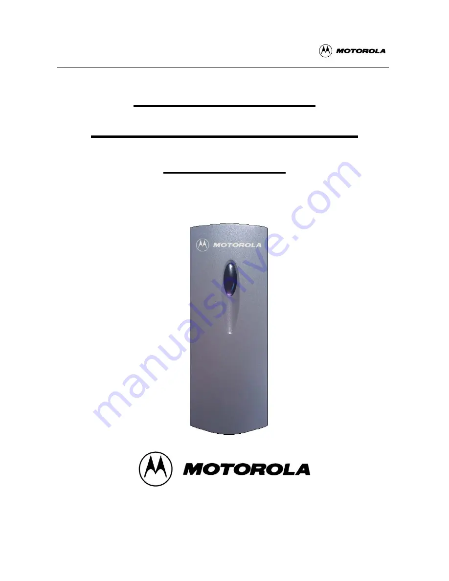
Open Format Reader 


Summary of Contents for FlexPass OFR100

Page 1: ...FlexPass OFR100 K02000 000 1 06 29 01 OPERATING AND INSTALLATION MANUAL FlexPass OFR100 Open Format Reader ...

Page 2: ...ions 3 2 Product Description 3 3 Features 4 4 Identifying Supplied Parts 4 5 Specification 4 6 Installation 5 7 Wire Color Coded Wiring 6 8 Wire Connection to A Host Controller 6 9 Wire Connection to SDC1000 7 10 Operation 7 11 FCC Registration Information 8 12 Warranty and Service 8 ...

Page 3: ...ugh the cabinet slots as they may touch voltage points or short out parts that could result in fire or electric shock Never spill liquid of any kind on the product 7 To reduce the risk of electric shock do not disassemble this product by yourself but take it to qualified service whenever service or repair is required 8 Unplug this product from the Direct Current DC power source and refer to qualif...

Page 4: ...tor Easy Mounting to a single gang box 4 Identifying supplied parts Please unpack and check the contents of the box Reader Module OFR100 Bezel Manual 1 ea 1 ea 1 ea 5 Specification Read Range Time Up to 4 10cm 300ms with Motorola FlexPass ASC 121T card and minimum read range 3 7 5cm Input Voltage Current DC 5V 12V 120mA at standby max 150mA Output Format 26 bit Wiegand or ABA Track II Magstripe Ex...

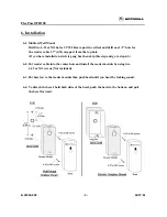
Page 5: ... top hole If you have installed an electric gang box then skip this step and go to step 6 2 6 2 Put reader cable into the center hole and install the reader module by using two 6 32 or M3 screws Not included 6 3 Put bezel on to the reader module then push bezel until you hear the locking sound 6 4 To detach the bezel hold both sides of the bezel push the bezel to the bottom and pull the bezel forw...

Page 6: ...re Power Ground VDC GND Black wire INPUT Beeper control Beeper Blue wire LED control LED Brown wire OUTPUT Wiegand Format Wiegand Data 0 Data 0 Green wire Wiegand Data 1 Data 1 White wire OUTPUT ABA Track II Format ABA Card Present CP Orange wire ABA Clock CLK White wire ABA Data Data Green wire 8 Wire Connection to a Host Controller ...

Page 7: ...LED will change color to Red again for the next reading 10 3 LED Control To change the LED colors you may connect the LED Control Input Brown wire to ground and the Green LED will turn on indicating that the reader is in standby mode Present proximity card and the LED will change color to Red then Green again for the next reading 10 4 Beeper Control In normal operation the reader generates one bee...

Page 8: ...his equipment does cause harmful interference to radio or television reception which can be determined by turning the radio or television off and on the user is encouraged to try to correct interference by one or more of the following measures 1 Reorient or relocate the receiving antenna 2 Increase the separation between the equipment and receiver 3 Connect the equipment into an outlet on another ...

Reviews: