background image

SE4750

INTEGRATION GUIDE

Summary of Contents for SE4750

Page 1: ...SE4750 INTEGRATION GUIDE ...

Page 2: ......

Page 3: ...SE4750 INTEGRATION GUIDE 72E 171726 01 Revision A November 2013 ...

Page 4: ... program in a network without written permission from Motorola The user agrees to maintain Motorola s copyright notice on the licensed programs delivered hereunder and to include the same on any authorized copies it makes in whole or in part The user agrees not to decompile disassemble decode or reverse engineer any licensed program delivered to the user or any portion thereof Motorola reserves th...

Page 5: ...iii Revision History Changes to the original manual are listed below Change Date Description 01 Rev A 11 2013 Initial release ...

Page 6: ...iv SE4750 Integration Guide ...

Page 7: ... 1 3 Illumination System 1 3 Illumination Control 1 3 Frame Rate Control 1 3 Chapter 2 Installation Introduction 2 1 General Information 2 1 Default Power Mode 2 1 Grounding 2 1 Electrostatic Discharge ESD 2 2 Environment 2 2 Power Supply Noise 2 2 Thermal Considerations 2 2 External Optics Imaging Lens Illumination LEDs and Aiming Element 2 5 Image and Document Capture 2 5 Regulatory Information ...

Page 8: ...lel Host Interface 3 1 I2C MIPI and Parallel Host Interface 3 2 MIPI and Parallel Host Interface 3 2 Parallel Host Interface for HSYNC VSYNC PIXCLK and PIX_DATA_x Signals 3 3 MIPI Host Interface 3 4 Technical Specifications 3 6 Supply Currents VCC VCC_ILLUM VDD_IO_HOST 3 3V 23C 3 8 Parallel and MIPI Host Interface with Laser Aim Engine Only without PL3307 Decoder 3 8 Sample Current Scope Plots 3 9...

Page 9: ...EL 0xF0 5 6 IMAGE_CAPTURE_MODE 0x73 5 7 PICKLIST_MODE 0x7B 5 7 PING 0x7A 5 7 POWER_MODE 0x5F 5 7 RD_SENSOR 0x51 5 8 RESET 0x57 5 8 TIME_TO_LOW_POWER 0x75 5 8 WR_SCRIPT 0x76 5 8 WR_SENSOR 0x50 5 8 Command Response Formats 5 9 Chapter 6 Application Notes Introduction 6 1 Image Acquisition 6 1 Output Data Format 6 2 Output Data Timing 6 2 Recommended Procedures 6 4 Normal Decode Mode 6 4 Snapshot Mod...

Page 10: ...viii SE4750 Integration Guide ...

Page 11: ...nding ESD and environmental considerations Chapter 3 Specifications provides technical specifications for the engine including decode ranges Chapter 4 Electrical Interface includes signal information and connector drawings Chapter 5 Control Interface describes the SE4750 s bi directional control interface Chapter 6 Application Notes describes SE4750 operating modes Appendix A Register Settings pro...

Page 12: ...98 39340011 pdf Aptina AR0134 mono 1 3 inch CMOS Digital Image Sensor Datasheet http www aptina com To receive a copy of this datasheet register with Aptina at http www aptina com extranet register jsp Molex connector specification 54809 Series http www molex com Kyocera connector specification 6283 Series http global kyocera com NOTE This symbol indicates something of special interest or importan...

Page 13: ...mber or product name Software type and version number Motorola responds to calls by e mail telephone or fax within the time limits set forth in support agreements If your problem cannot be solved by Motorola Solutions support you may need to return your equipment for servicing and will be given specific directions Motorola is not responsible for any damages incurred during shipment if the approved...

Page 14: ...xii SE4750 Integration Guide ...

Page 15: ... digital images for transmission to a decoder to decode a bar code of any format supported by the decoding software The SE4750 uses laser aiming and LED illumination WARNING This device emits CDRH IEC Class 2 laser and IEC Class 1M light Do not stare into beam ...

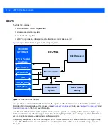
Page 16: ...igure 4 3 on page 4 5 for host flex information A Visible Laser Diode and associated optics aiming element generate an aiming pattern and dual high output LEDs provide illumination for the imager under virtually any lighting condition The aiming subsystem illumination system and frame rate are under dynamic software control The primary component of the SE4750 imager is a 1 3 format CMOS 1280 H x 9...

Page 17: ...or off If the aiming system is turned off during exposure brightness of the aiming pattern decreases as exposure increases The aiming subsystem can also be turned off completely Motorola recommends shutting aiming off three frames prior to capturing documents to prevent the aiming pattern from appearing faintly in captured images Note that this is not necessary for bar code decoding Illumination S...

Page 18: ...1 4 SE4750 Integration Guide ...

Page 19: ... configure the PL3300 for one of these modes using config 0 and config 1 signals in order to achieve expected illumination brightness IMPORTANT Mixing Bus Powered USB Mode with VCC_ILLUM 3 3V does not achieve the expected illumination brightness This results in decode performance degradation and should be avoided Grounding The chassis is at ground Isolate the SE4750 and host if installing the engi...

Page 20: ...te heat during operation The chassis temperature can reach as high as 72 C when the engine is running at 54 frames per second with full illumination and aiming on These extreme conditions can increase sensor noise degrade image quality and impact the laser diode s longevity Use care when designing the SE4750 for integration into the target application As a protective measure for the laser diode at...

Page 21: ...ot represents the condition that the engine is in still air and with no heat sink attached while the air temperature is measured as the ambient temperature The scanning time is measured between the trigger event pulling the trigger and the end of the scanning session decoding The scanning duty cycle is the percentage of time when the engine is in full scanning mode 0 scanning duty cycle in level t...

Page 22: ...12 scans per minute equals 20 scanning duty cycle Running in continuous 54 fps video mode with both aiming and illumination enabled full time is highly uncommon If a higher ambient temperature or higher scan rate is desired the recommendations to reduce engine power consumption and increase heat removal include but are not limited to Turning off the engine aiming and illumination whenever possible...

Page 23: ...oduct The illumination system also meets emission limits of exempt group according to Lamp Eye Safety Standard Any product containing the SE4750 can meet these same regulations Contact a Motorola sales representative for further details Laser products sold in North America must be reported to the U S Food and Drug Administration Center for Devices and Radiological Health CDRH via a Laser Radiation...

Page 24: ...napshot or video mode Notes Unless otherwise specified Chassis is at ground Holes marked A are engine locating aides Holes marked B are threaded mounting holes Slot marked C is SE4750 SR LSR AIM specific locating aid It is recommended to secure the engine using a combination of two locating pins and two mounting screws which must include A1 and B1 To ensure mounting compatibility with other engine...

Page 25: ...ndow material can affect the performance of the SE4750 Positioning the Exit Window Position the window so that illumination system light reflected off the inside of the window is not reflected back into the engine see Recommended Exit Window Information on page 2 14 If the designed enclosure cannot accommodate the recommended window angle contact Motorola to discuss positioning requirements An imp...

Page 26: ...erefore polysiloxane coating is strongly recommended Acrylic can be laser cut into odd shapes and ultrasonically welded Cell Cast ADC ASTM ADC Also known as CR 39TM Allyl Diglycol Carbonate ADC is a thermal setting plastic produced by cell casting Most plastic eyeglasses sold today are uncoated cell cast CR 39 This material has excellent chemical and environmental resistance and reasonably good im...

Page 27: ... Coatings If using an anti reflective AR coating the specifications in Table 2 3 apply When using anti reflection coating the application of additional hard coating is not recommended Recess the exit window to minimize scratches and digs Table 2 2 Taber Test Results on Common Exit Window Materials Sample Haze 100 cycles Haze 500 cycles Abrasion Resistance Chemically Tempered Glass 1 20 1 50 Best P...

Page 28: ...2 10 SE4750 Integration Guide Optical Path Imaging Field of View Figure 2 5 SE4750 SR LSR AIM Optical Path Imaging Field of View ...

Page 29: ...Installation 2 11 Aiming Pattern Figure 2 6 SE4750 SR LSR AIM Optical Path Aiming Pattern ...

Page 30: ...50 Integration Guide Imaging and Aiming Parallax Figure 2 7 SE4750 SR LSR AIM Optical Path Imaging and Aiming Parallax Due to parallax the aiming dot is located at the center of the image at 203 2 mm 8 0 inches ...

Page 31: ... imaging field of view Obstructing the aiming pattern Note for Engine Mounting in a Hands Free Application For optimum performance in presentation mode allow only bar codes to enter the engine clear aperture Other moving objects in the engine clear aperture can cause a false trigger of the object detection system For example in a table top mounted application the engine should face down such that ...

Page 32: ...age blemishes Table 2 4 Recommended Exit Window Information Tilted Window Distance from Engine Front Surface b in mm 5 5 8 10 12 15 20 25 Window Specification Angle Non coated minimum window positive tilt c 40o 40o 38o 37o 35o 35o 35o Non coated minimum window negative tilt c N A N A 52o 52o 27o 27o 27o AR coated one side minimum window positive tilt c 40o 40o 35o 35o 35o 33o 32o AR coated one sid...

Page 33: ... this effect Increase window size such that stray light can escape the system without reflecting back onto the engine See Example 1 in Figure 2 11 and Figure 2 12 Occupy the stray light zone only with black matte surfaces that do not cause strong reflections back onto the engine See Example 2 in Figure 2 11 and Figure 2 12 Block light from reaching the stray light zone by placing a matte black opt...

Page 34: ...SR LSR AIM Parallel Window Integration Examples Example 1 The engine clear aperture is unobstructed Housing features are outside of the stray light zone Example 2 The engine clear aperture is unobstructed Housing features which are inside of the stray light zone have black matte surfaces ...

Page 35: ...e is unobstructed Housing features are outside of the stray light zone Example 2 The engine clear aperture is unobstructed Housing features which are inside of the stray light zone have black matte surfaces Example 3 The engine clear aperture is unobstructed A baffle feature with black matte surfaces prevents light from reaching other housing features ...

Page 36: ...2 18 SE4750 Integration Guide ...

Page 37: ... specifications decode zone and exit window characteristics Electrical Characteristics Power MIPI and Parallel Host Interface Table 3 1 Power MIPI and Parallel Host Interface Symbol Parameter Condition Minimum Typical Maximum Units VCC Supply Voltage 3 0 3 3 3 6 V VDD_IO_HOST Supply Voltage 1 7 3 3 3 6 V VCC_ILLUM Supply Voltage Illumination 3 0 3 3 5 5 V ...

Page 38: ... V V VIH Input High Voltage 0 7 VDD_IO_HOST VDD_IO_HOST 0 5 V VIL Input Low Voltage 0 5 0 3 VDD_IO_HOST V TR Rise Time Set by external pull up and load 30 to 70 VDD_IO_HOST 1 3 Rext Cb ns TF Fall Time 20 250 ns Cb Load Capacitance 10 400 pF Table 3 3 EXT_ILLUM_EN Signal Symbol Parameter Conditions Minimum Typ Maximum Units VOH Output High Voltage VDD_IO_HOST 3 3 VDD_IO_HOST 1 8 IOH 2mA VDD_IO_HOST...

Page 39: ...l Host Interface for HSYNC VSYNC PIXCLK and PIX_DATA_0 Through PIX_DATA_7 Signals Symbol Parameter Conditions Minimum Typ Maximum Units VOH Output High Voltage VDD_IO_HOST 3 3 VDD_IO_HOST 1 8 IOH 8mA VDD_IO_HOST 0 2 VDD_IO_HOST 0 45 V VOL Output Low Voltage VDD_IO_HOST 3 3 VDD_IO_HOST 1 8 IOL 8mA 0 2 0 45 V ...

Page 40: ... Time that the HS clock is driven by the transmitter prior to any associated data lane beginning the transition from LP to HS mode 110 ns THS PREPARE THS ZERO THS PREPARE time that the transmitter drives the HS 0 state prior to transmitting the sync sequence 360 ns T HS_TRAIL Time that the transmitter drives the flipped differential state after last payload data bit of an HS transmission burst 118...

Page 41: ...ns 3 5 V LP0H LP output high level 1 2 V V CMTX HS transmit static common mode voltage 180 mV V OD HS transmit differential voltage 200 mV Table 3 5 MIPI Host Interface Continued Parameter Description Typical Units ...

Page 42: ...None Skew Tolerance 60º see Figure 3 5 on page 3 11 Pitch Angle 60º see Figure 3 5 on page 3 11 Roll 360º see Figure 3 5 on page 3 11 Ambient Light Immunity Sunlight 10 000 ft candles 107 639 lux Imaging Sensor Image Resolution Field of View FOV 1280 horizontal X 960 vertical pixels 48 0º horizontal 36 7º vertical Focusing Distance from Front of Engine SR 177 8 mm 7 0 inches Laser Aiming Element V...

Page 43: ...º to 60º C 22º to 140º F 40º to 70º C 40º to 158º F See Thermal Considerations on page 2 2 for more information Humidity 95 RH non condensing at 60º C Maximum Engine Dimensions 11 8 mm H x 21 5 mm W x 16 3 mm D 0 46 in H x 0 85 in W x 0 64 in D Weight 8 0 grams 0 28 oz Electrical Interface 21 pin 0 3 mm pitch ZIF connector See Chapter 4 Electrical Interface for more information Table 3 6 SE4750 Te...

Page 44: ... Standby Idle PEAK 30 1 30 350 1 360 1 0 3 Not in low power mode but not triggered RMS 20 1 20 0 0 0 3 Image Acquisition PEAK 260 260 350 1 360 1 50 3 Illumination off aim on 2 RMS 190 190 0 0 30 3 Image Acquisition with Illumination PEAK 580 260 350 360 50 3 Normal acquisition mode aim on 2 RMS 440 190 240 170 30 3 Bus Pwr USB 500mA PEAK 400 260 N A 200 50 3 VCC_ILLUM should be USB 5V RMS 340 180...

Page 45: ...Specifications 3 9 Sample Current Scope Plots Figure 3 1 Total Current VCC_ILLUM VCC VDD_IO_HOST Figure 3 2 VCC Current ...

Page 46: ...3 10 SE4750 Integration Guide Figure 3 3 VCC_ILLUM Current Figure 3 4 VDD_IO Host Current Parallel Version ...

Page 47: ...h and Roll Measured on a 20 mil Code 39 symbol at a distance of 5 inches Tolerance for skew and pitch is reduced at extreme ends of the working range Figure 3 5 Skew Pitch and Roll Skew Pitch Roll 60 from normal 60 from normal 360 ...

Page 48: ...ar code in field of view Note Photographic quality bar code at 18o tilt pitch angle under 30 fcd ambient illumination Table 3 9 SE4750 SR Decode Distances Dark Room Bar Code Type Near Distance in typical Far Distance in typical 3 mil Code 39 2 8 6 2 5 mil Code 128 2 3 8 7 5 mil PDF417 3 0 8 1 6 67mil PDF417 2 2 10 6 10 mil Data Matrix 2 4 10 6 100 UPCA 1 6 21 6 15 mil Code 128 2 4 21 3 20 0 mil Co...

Page 49: ...Signal Name I O Notes 1 GND Ground 2 GND Ground 3 I2C_CLK I I2 C clock 4 I2C_DATA I O I2C data 5 VSYNC O Vertical sync 6 PIX_DATA_7 O Sensor pixel data MSB 7 PIX_DATA_6 O Sensor pixel data 8 PIX_DATA_5 O Sensor pixel data 9 PIX_DATA_4 O Sensor pixel data 10 PIX_DATA_3 O Sensor pixel data 11 PIX_DATA_2 O Sensor pixel data 12 PIX_DATA_1 O Sensor pixel data 13 PIX_DATA_0 O Sensor pixel data LSB 14 EX...

Page 50: ... 8 GND GND 9 CP O MIPI clock 10 GND GND 11 CN O MIPI clock 12 GND GND used to connect GUARD TRACE on flex 13 VDD_IO_HOST PWR In VDD_IO_HOST host digital logic level of EXT_ILLUM_EN and I2 C signals 14 EXT_ILLUM_EN O EXT_ILLUM_EN pulled up to VDD_IO_HOST 15 Reserved Reserved 16 VCC PWR In Aiming and logic power 17 VCC_ILLUM PWR In Illumination power 18 VCC_ILLUM PWR In Illumination power 19 I2C_CLK...

Page 51: ...ector Drawings For detailed connector information refer to the manufacturer s specifications Kyocera 6283 Series Figure 4 1 21 Pin ZIF Connector SE4750 Engine to Flex Kyocera 6283 Series No of Position A B C 21 6 0 mm 8 3 mm 6 7 mm ...

Page 52: ...e 4 2 MIPI Host Flex p n 15 162392 xx PIN 1 PIN 1 EXPOSED FINGERS EXPOSED FINGERS FACING DOWN FACING DOWN PIN 1 PIN 1 PIN 2 PIN 2 PIN 3 PIN 3 ZOOM VIEW ZOOM VIEW EXPOSED FINGERS EXPOSED FINGERS FACING UP FACING UP ENGINE END ENGINE END ...

Page 53: ...Electrical Interface 4 5 Figure 4 3 Parallel Host Flex p n 15 171522 xx ...

Page 54: ...n the VCC supply Figure 4 4 Power up Sequence Power down To power down the engine it is recommended that the host system send a command to the engine that causes it to enter the low power standby state This ensures that critical operations such as flash writes are not interrupted when power is removed Once the standby command is acknowledged the power supplies can be safely removed The VCC_ILLUM a...

Page 55: ...ACQUISITION_MODE 0x5B Optimizes the SE4750 for a specific operation AIM 0x55 Turns the aim pattern on and off AIM_DURING_EXPOSURE 0x56 Captures the aim pattern in the image AUTO_POWER_REDUCTION 0x74 Places the SE4750 in a low power state when idle ENTER_BOOTLOADER 0x91 Enters bootloader mode EXECUTE_SCRIPT 0x77 Executes a programmed script EXTERNAL_ILLUMINATION 0x5A Controls the operation of the E...

Page 56: ...eads the Aptina AR0134 registers RESET 0x57 Returns engine components to a default state TIME_TO_LOW_POWER 0x75 Sets the length of time the SE4750 is idle before entering low power mode WR_SCRIPT 0x76 Programs more than one SE4750 command into one script WR_SENSOR 0x50 Writes to the Aptina AR0134 registers Table 5 1 SE4750 Command List Continued I2 C Command Set Opcode Description ...

Page 57: ...ined by the I2 C specification SLA W is 0xB8 Slave Addr Write Op or Slave Address is 0x5C or 0xB8 after shifting into 7 MSBs Write Op is 0x00 Opcode is 1 byte from the SE4750 Command Op column in Table 5 3 on page 5 9 SE4750 Cmd Data is from the SE4750 Command Data column in Table 5 3 on page 5 9 This can be NULL Checksum is a 1 byte checksum of the SE4750 Cmd Data bytes See Command Checksum on pa...

Page 58: ...lists status codes for single errors Note that these error codes are bit positions within the status byte and two errors can occur e g NAK and AIM_POWER_FAIL resulting in values not listed in this table Table 5 2 Response Status Codes Status Value Cause Meaning ACK 0x80 Command was successful NAK 0x82 Bit 1 set Command failed Possible causes are Invalid opcode Invalid command format Invalid parame...

Page 59: ... turn aiming on although it turns aiming on upon the next ACQUISITION Start command AIM_DURING_EXPOSURE 0x56 When enabled this keeps the aiming pattern on when capturing an image meaning the pattern is visible in the image When disabled the aiming pattern is not visible in acquired images The default is disabled Enabling AIM_DURING_EXPOSURE has no effect unless AIM is also on Enabling AIM_DURING_E...

Page 60: ...last GET_EXTENDED_STATUS command These bits are reported in the second byte of the extended status data Note that these conditions are bit positions within the extended status bytes these conditions can occur simultaneously resulting in values not shown below Operating States Individual Bytes 0x01 The internal temperature is approaching the threshold at which it can affect laser operation 0x08 The...

Page 61: ...e arguments 0x02 0x3C One picklist frame every 30 frames use the arguments 0x01 0x1E Configure PICKLIST_MODE before starting acquisition When acquisition starts the picklist sequence begins The first M frames are picklist frames and the next N M frames are non picklist frames This sequences cycles every N frames The host system must track count every frame to determine when picklist frames and non...

Page 62: ...pt 0 through Script 9 and a total of 150 bytes for all scripts Exceeding these limits results in a NAK status code The general format for this command is 0x76 Script Len C1Len C1Op C1Data C2Len C2Op C2Data C3Len C3Op C3Data Checksum Example To program script 2 with AIM_ON ILLUM_ON and ACQUISITION_ON format the WR_SCRIPT command as follows 0x76 0x02 0x09 0x02 0x55 0x01 0x02 0x59 0x01 0x02 0x58 0x01...

Page 63: ...0x00 Off 0x01 On 0x56 RESET 0x57 B 0x00 Sensor 0x01 SE4750 0x57 ACQUISITION 0x58 B 0x00 Stop 0x01 Start 0x58 ILLUMINATION_DURING_EXPOSURE 0x59 B 0x00 Off 0x01 On 0x59 EXTERNAL_ILLUMINATION 0x5A B 0x00 Floating Input 0x01 On 0x02 Off 0x03 Follow Internal Illumination 0x04 Follow Trigger 0x05 Alternate with Internal Illumination 0x5A ACQUISITION_MODE 0x5B B 0x00 Barcode Decode 0x01 Document Capture ...

Page 64: ... 1 s increments 0x00 5 ms 0x75 WR_SCRIPT Note 3 0x76 B Script A Script Data 0x76 EXECUTE_SCRIPT 0x77 B Script 0x77 GET_EXTENDED_STATUS 0x79 0x79 PING 0x7A 0x7A PICKLIST_MODE 0x7B B Picklist Frames B Frames 0x7B Table 5 3 SE4750 Command and Response Formats Continued Function SE4750 Command SE4750 Response Op SE4750 Command DataNote1 Op SE4750 Response DataNote2 Notes 1 Every command has a 1 byte c...

Page 65: ...mber 1 16 DATE_MANUFACTURE Engine manufacturing date 2 7 DATE_SERVICE Engine service date 3 7 SCANNER_BOOTLOADER_FIRMWARE_VERSION Engine bootloader version 10 8 SCANNER_PRODUCTCODE_FIRMWARE_VERSION Engine firmware version 20004 8 ENGINE_ID Engine ID number 20005 1 HARDWARE_VERSION Engine hardware version 20006 1 DEVICE_CLASS Engine device class 20007 18 GUID Generally Unique ID 14 32 ...

Page 66: ...5 12 SE4750 Integration Guide ...

Page 67: ... image acquisition and power consumption information LED illumination is required for decoding Image Acquisition The SE4750 contains a 1280 H x 960 V CMOS sensor Figure 6 1 illustrates pixel output format and Figure 6 2 and Figure 6 3 show basic timing information ...

Page 68: ... Signals Figure 6 3 Pixel Data Timing Example P0 0 P0 1 P0 2 P 0 n 1 P0 n P1 0 P1 1 P1 2 P 1 n 1 P1 n 00 00 00 00 00 00 00 00 00 00 00 00 Pm 1 0 Pm 1 1 P m 1 n 1 Pm 1 n Pm 0 Pm 1 P m n 1 Pm n 00 00 00 00 00 00 00 00 00 00 00 00 00 00 00 00 00 00 00 00 00 00 00 00 00 00 00 00 00 00 00 00 00 00 00 00 00 00 00 00 00 00 00 00 00 00 00 00 00 00 00 00 00 00 00 00 00 00 00 00 VALID IMAGE HORIZONTAL BLANK...

Page 69: ...1280 17 23 µs With stats enabled 1360 18 31 µs P1 Frame start blanking 6 0 08 µs P2 Frame end blanking 6 0 08 µs Q Horizontal blanking 108 1 45 µs With stats enabled 28 0 37 µs A Q Row time 1388 18 69 µs V Vertical blanking 51 356 691 7 µs Nrows Frame valid time 1 332 384 17 94 ms F Total frame time 1 383 836 18 6 ms ...

Page 70: ...ion Stop command The host sends the Barcode Decode mode command The SE4750 optimizes the image output for bar code decoding The SE4750 enters standby mode or low power mode if enabled Upon a trigger pull The host sends the Illumination On command The SE4750 exits standby mode or low power mode if enabled The host sends the Aim On command The host sends the Acquisition Start command The SE4750 begi...

Page 71: ...e if enabled Upon a trigger pull The host sends the Illumination On command The SE4750 exits standby mode or low power mode if enabled The host sends the Aim On command The host sends the Acquisition Start command The SE4750 begins outputting images Starting with the first frame every 60th frame is a picklist frame 1 61 121 181 The host attempts to decode the images Upon a good decode or trigger r...

Page 72: ...tandby or low power mode Upon the host detecting motion The host sends the Aim On command The host sends the Illumination Power Full command The host sends the Barcode Decode mode command The SE4750 optimizes the image output for bar code decoding The host attempts to decode the images Upon a good decode The host sends the Aim Off command The host sends the Illumination Power Off command Off is th...

Page 73: ...on The host sends the Barcode Decode mode command The host sends the Aim On command Upon a trigger pull The host sends the Illumination On command The SE4750 optimizes the image output for bar code decoding The host attempts to decode the images Upon a good decode or trigger release The host sends the Aim Off command The host sends the Illumination Off command The host sends the Motion Detect mode...

Page 74: ... 60th frame is a picklist frame 1 61 121 181 Upon the host detecting motion The host sends the Barcode Decode mode command The host sends the Aim On command Upon a trigger pull The host sends the Illumination On command The SE4750 optimizes the image output for bar code decoding The host attempts to decode the images Upon a good decode or trigger release The host sends the Aim Off command The host...

Page 75: ...nters low power mode Upon a trigger pull The host sends the Illumination On command The SE4750 if in low power mode exits low power mode either Reduced or Sleep The host sends the Aim On command The host sends the Acquisition Start command The SE4750 captures an image Upon completion of an image capture The SE4750 stops outputting image The host sends the Acquisition Stop command The host sends th...

Page 76: ...ts low power mode either Reduced or Sleep The host sends the Aim On command The host sends the Acquisition Start command The SE4750 begins outputting video stream Upon a trigger release The host sends the Acquisition Stop command The SE4750 stops outputting the video stream The host sends the Aim Off command The host sends the Illumination Off command The SE4750 when all conditions are met enters ...

Page 77: ...APPENDIX A REGISTER SETTINGS For information on register settings for the engine refer to the Aptina AR0134 1 3 1 2 Mp CMOS Digital Image Sensor Datasheet available at http www aptina com ...

Page 78: ...A 2 SE4750 Integration Guide ...

Page 79: ... 5 5 command format 5 3 5 9 command list 5 1 data formats 5 11 parameter numbers 5 11 recommendations 6 4 6 10 auto aim mode 6 7 level trigger mode 6 4 picklist in auto aim mode 6 8 picklist in level trigger mode 6 5 presentation mode 6 6 snapshot mode 6 9 video mode 6 10 response format 5 3 5 9 status codes 5 4 transactions 5 3 conventions notational x D data formats 5 11 decode distances 3 12 de...

Page 80: ...2 5 information service xi installation environment 2 2 ESD 2 2 external optics 2 5 grounding 2 1 housing 2 7 mounting 2 6 mounting diagram 2 6 optical considerations 2 7 positioning exit window 2 7 thermal considerations 2 2 L laser 1 3 LED 1 2 1 3 3 6 M mounting 2 6 diagram 2 6 N notational conventions x O optical 2 7 aiming pattern 2 11 avoiding scratched windows 2 7 engine clear aperture 2 13 ...

Page 81: ...l 3 6 3 11 snapshot mode 6 9 specular dead zone 3 6 status codes 5 4 T technical specifications electrical characteristics 3 1 engine specs 3 6 temperature specification 3 7 thermal considerations 2 2 timing diagrams 6 2 V vibration specification 3 7 video mode 6 10 visible laser diode 1 2 3 6 W weight 3 7 WVGA 1 2 Z ZIF connector 1 2 ...

Page 82: ...Index 4 SE4750 Integration Guide ...

Page 83: ...________ What topics need to be added to the index if applicable ______________________________________________________________________________________ ______________________________________________________________________________________ ______________________________________________________________________________________ __________________________________________________________________________...

Page 84: ......

Page 85: ......

Page 86: ...800 927 9626 http www motorolasolutions com MOTOROLA MOTO MOTOROLA SOLUTIONS and the Stylized M Logo are trademarks or registered trademarks of Motorola Trademark Holdings LLC and are used under license All other trademarks are the property of their respective owners 2013 Motorola Solutions Inc All Rights Reserved ...

Reviews: