background image


4pre


User Guide for Windows


1280 Massachusetts Avenue

Cambridge, MA 02138

Business voice: (617) 576-2760

Business fax: (617) 576-3609

Web site: www.motu.com

Tech support: www.motu.com/support

Summary of Contents for 4pre

Page 1: ... 4pre User Guide for Windows 1280 Massachusetts Avenue Cambridge MA 02138 Business voice 617 576 2760 Business fax 617 576 3609 Web site www motu com Tech support www motu com support ...

Page 2: ...ntthisequipment againstdefectsinmaterialsandworkmanshipforaperiodofTWO 2 YEARSfrom thedateoforiginalretailpurchase Thiswarrantyappliesonlytohardwareproducts MOTUsoftwareislicensedandwarrantedpursuanttoseparatewrittenstatements Ifyoudiscoveradefect firstwriteorcallMarkoftheUnicornat 617 576 2760to obtainaReturnMerchandiseAuthorizationNumber Noservicewillbeperformedon anyproductreturnedwithoutpriora...

Page 3: ...Audio Console 11 About the 4pre 15 Packing List and System Requirements 17 Installing the 4pre Software 19 Installing the 4pre Hardware Part2 Usingthe4pre 31 MOTU Audio Console 35 4pre Front Panel Operation 39 Configuring Host Audio Software 45 Reducing Monitoring Latency 51 CueMix FX 75 MOTU SMPTE Console 79 Troubleshooting ...

Page 4: ...4 ...

Page 5: ...Part1 GettingStarted ...

Page 6: ......

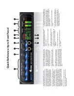
Page 7: ... knob to control the main outs and the headphone jack below the knob which mirrors the main outs 4 Turn the PHONES knob to control the headphone jack volume below it When power is off push the PHONES knob to power on the 4pre push and hold to turn it off When connected to the computer via FireWire the 4pre is powered by its FireWire connection When connected via USB it must be powered with the inc...

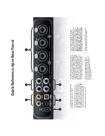
Page 8: ...ncoder To toggle 48V phantom power for the XLR mic input push and hold the corre sponding front panel encoder The TRS jacks for inputs 3 4 have higher impedance for DI guitar connections 4 The 4pre s analog line outputs operate as separate outputs on balanced 4dB TRS tip ring sleeve quarter inch connectors that can also accept an unbal anced plug They are equipped with 24 bit 128x oversampling con...

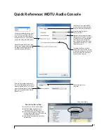
Page 9: ...veRT drivers and instead only supportsWDM drivers Choose the global sample rate for the system here Choosing a smaller setting here reduces the delay you may hear when listening to live input that you are running through effects plug ins in your software But lower settings also increase the strain on your computer For details see Samples Per Buffer on page 33 Click the 4pre tab to access this sett...

Page 10: ...10 ...

Page 11: ...F digital I O at sample rates up to 96 kHz SMPTE synchronization Headphone jack with independent output and volume control Extra headphone jack that mirrors the main outs Front panel volume control of the main outs Front panel mixing of live inputs Front panel metering and status LEDs Stand alone operation Mac and Windows drivers for multi channel operationandacross the boardcompatibilitywith any ...

Page 12: ...settings for guitars synths effects modules and a wide variety of analog inputs for optimum levels Different trim configurations can then be saved as files on disk for instant recall S PDIF The 4pre rear panel provides coaxial S PDIF input and output SMPTE time code synchronization The 4pre can resolve directly to SMPTE time code via any analog input without a separate synchronizer It can also gen...

Page 13: ... rear panel Alternately this MAIN knob can be programmed to control any combination of outputs analog and or digital Status and metering LEDs The LED section provides visual indication of audio levels audio activity status and the current settings for all front panel controls 16 BIT AND 24 BIT RECORDING The 4pre system handles all data with a 24 bit signal path regardless of the I O format You can...

Page 14: ...ixing features digitally controlled trims and other settings in your MOTU audio interface CueMix FX provides many advanced features such as an accurate instrument tuner and an extensive arsenal of audio analysis tools including a real time FFT spectrogram waterfall display oscilloscope and phase analysis tools HOST AUDIO SOFTWARE The 4pre system ships with standard Windows drivers that allow you t...

Page 15: ...based PC compatible or faster equipped with at least one USB2 or FireWire port 1 GB RAM 2 GB or more recommended Windows 7 orVista 32 or 64 bit Vista SP 2 or later required Available FireWire or high speed USB 2 0 port A large hard drive preferably at least 250 GB PLEASE REGISTER TODAY Please register your 4pre today There are two ways to register Visit www motu com register OR Fill out and mail t...

Page 16: ...P A C K I N G L I S T A N D S Y S T E M R E Q U I R E M E N T S 16 ...

Page 17: ...aller locate the folder containing the download 2 Read the Read Me file for installation assistance and other important information 3 Open the Setup Audio application 4 Follow the directions that the installer gives you Drivers are installed along with MOTU Audio Console CueMix FX and other components summarized in the table below Software component Purpose For more information MOTU audio drivers ...

Page 18: ...re page 39 WaveRT Uncheckthisoptionif theWindowsaudiosoftware you are using with your MOTU audio interface does not support Windows WaveRT drivers and instead only supports WDM drivers MOTU AUDIO CONSOLE MOTU Audio Console available in the Start menu gives you access to all of the settings in the 4pre such as the clock source and sample rate For complete details see chapter 5 MOTU Audio Console pa...

Page 19: ... computer based mixing FX ConnectmultipleMOTUinterfaces 26 Connect additional 4pre or other audio interfaces IMPORTANT NOTE BEFORE YOU BEGIN Before you begin installing the 4pre or any bus powered device take these important precautionary measures to avoid damaging the sensitive electrical components in your computer the 4pre or other devices being connected Turn off the computer Turn off the 4pre...

Page 20: ...onnection to the computer For complete information see Bus power requirements on page 23 If you use USB2 you must also use the DC power supply included with your 4pre as USB2 does not supply enough power by itself If you are connecting via FireWire 1 Before you begin make sure your computer and the 4pre are switched off 2 Plug one end of the 4pre FireWire cable included into the FireWire socket on...

Page 21: ...ure 4 1 3 Plug the squared type B plug of the USB cable into the 4pre I O as shown below in Figure 4 1 Figure 4 1 Connecting the 4pre to the computer via USB Switching Between FireWire and USB Most of the time the 4pre can detect whether a FireWire or a USB cable is connected to it and it will automatically switch to FireWire operation or USB operation accordingly Some FireWire or USB ports that d...

Page 22: ...trim The ten segment MAIN OUT meters provide visual feedback as you turn the knob The 4pre s input trims are digitally controlled so they allow you to make fine tuned adjustments in approximately 1dB increments You can also adjust trim in the MOTU CueMix FX software See Input trim on page 53 20 dB pad Each XLR mic input is equipped with a 20 dB pad To toggle the pad for a mic input 1 Push the MIX ...

Page 23: ...r requirements The 4pre draws all the power it needs from the FireWire bus connection to the computer However the FireWire connection to the computer must meet all of the requirements discussed below 9 pin and 6 pin FireWire connectors The 4pre can only draw power over the FireWire bus from a 9 pin to 9 pin cable or a 6 pin to 9 pin cable It cannot draw power from a FireWire cable with a 4 pin con...

Page 24: ...ire bus and there are no limits to running time Bus power from a battery powered laptop The laptop is being powered by its own battery and the 4pre is being powered by its FireWire connection to the computer So the laptop battery is supplying power to both the laptop and the 4pre This is the most compact and portable operating scenario Running time is determined by the capacity of the laptop batte...

Page 25: ...ware or you can use the 4pre s CueMix no latency mixer You can control the 4pre s four separate mixes from the front panel or from the included CueMix FX software S PDIF DAT deck quarter inch analog outs synthesizer monitors Figure 4 4 A typical 4pre studio setup headphones 4pre rear panel FireWire or USB2 guitars with or without an amp PC mics condenser or dynamic 4pre front panel headphones Alte...

Page 26: ...ster Clock Source from the menu in the General tab Figure 4 7 You can choose any available sync source from any connected interface as shown in Figure 4 7 giving you a great deal of flexibility in choosing a clock source A separate Clock menu is provided for any interfaces not chosen as the master clock source as demonstrated with the 828mk3 Hybrid in Figure 4 7 You can either resolve the interfac...

Page 27: ...expansion products in the form of a cardbus PC card adaptor ExpressCard adaptor or PCI card allow you to add a second FireWire bus to your computer It may be possible to add additional MOTU FireWire interfaces connected to such a third party product depending on the performance of the product and the performance of your host computer ...

Page 28: ...I N S T A L L I N G T H E 4 P R E H A R D W A R E 28 ...

Page 29: ...Part2 Usingthe4pre ...

Page 30: ......

Page 31: ...iver preferences For example in Cubase or Nuendo open the Device Setup window clickVST Audio System and choose MOTU Audio ASIO from the ASIO Driver menu Then click the MOTU Audio ASIO item in the list and click the Control Panel button Most applications provide access only to basic settings such as sample rate and clock source For access to all settings open MOTU Audio Console using one of the tec...

Page 32: ...ource setting Internal Use the Internal setting when you want the 4pre to operate under its own digital audio clock For example you may be in a situation where all you are doing is playing tracks off hard disk in your digital audio software on the computer In a situation like this you most often don t need to reference an external clock of any kind Another example is transferring a mix to DAT You ...

Page 33: ...ing impacts the following things The strain on your computer s CPU The delay you hear when routing a live signal through your host audio software plug ins How responsive the transport controls are in your software This setting presents you with a trade off between the processing power of your computer and the delay of live audio as it is being processed by plug ins If you reduce the Samples Per Bu...

Page 34: ...ssing 4pre channels from within the software make sure to enable the Use Stereo Pairs for Windows Audio option Use WaveRT for Windows audio If your host software supports WaveRT enable this option Consult your host application documentation for details Enable Pedal This setting applies to other MOTU audio interfaces but it does not apply to the 4pre 4PRE TAB SETTINGS Phones Assign The PhonesAssign...

Page 35: ...and hold the knob to turn it off MAIN OUT VOLUME Use the MAIN knob to control the volume of the main outputs 1 2 on the back panel This knob also controls the volume of the headphone jack below it which always mirrors the main outs As you turn the MAIN knob to adjust volume the MAIN OUT ladder LEDs Figure 6 1 provide visual feedback PHONES Use the PHONES knob Figure 6 1 to control the volume of th...

Page 36: ...ording device of some kind or to an effects processor Choosing a mix to control The 4pre front panel controls only one mix at a time To choose which mix you are controlling push the MIX VOL knob Figure 6 1 repeatedly The current mix LEDs Figure 6 3 indicate the currently selected mix main line spdif or ph phones The factory default setting is trim explained later so make sure one of these four mix...

Page 37: ...t is by default grouped as a stereo pair In addition there is no knob on the front panel for S PDIF volume control Use the included CueMix FX software to control the S DIF input level panning and mono stereo grouping See chapter 9 CueMix FX page 51 Trim pad and phantom power controls are always independent regardless of stereo pairing Adjusting input trim When you push the Mix Volume knob Figure 6...

Page 38: ...your mix VISUAL FEEDBACK WHEN ADJUSTING MIX CONTROLS When you turn a knob to adjust volume or pan the ten segment MAIN OUT ladder LEDs provide visual feedback as you turn the knob METERING AND ACTIVITY LEDS The Line Out LEDs Figure 6 3 indicate output activity on the quarter inch Line Out 3 4 jacks The SPDIF LEDs Figure 6 3 indicate input and output activity on the digital audio jacks The MAIN OUT...

Page 39: ...AUDIO CONSOLE Before you run your host audio software launch MOTU Audio Console to configure your 4pre hardware MOTU Audio Console provides settings to configure your audio interface and enable the desired inputs and outputs Only enabled inputs and outputs will be available to your software so this is an important step For complete details see chapter 5 MOTU Audio Console page 31 Figure 7 1 MOTU A...

Page 40: ... can choose any other output pair If you choose Phones 1 2 this setting makes the headphone jack serve as its own independent output pair As a result you ll see Phones 1 2 as an additional audio destination in your host s audio output menus When operating at high sample rates the phones must mirror one of the other output pairs The headphone jack labeled MAIN is hard wired to mirror the main outs ...

Page 41: ... Device and Output Audio Device menus as shown below in Figure 7 4 To enable or disable input or output channels click the Input Config or Output Config buttons Figure 7 4 Enabling the MOTU Audio ASIO driver in Live Reason and Record In Propellerhead Reason or Record go to the Preferences window choose Audio preferences from the menu and choose MOTU Audio ASIO from the Audio Card Driver menu as sh...

Page 42: ...Mode as shown below Figure 7 7 Enabling the MOTU Audio ASIO driver in SONAR 4 Next in the Audio preferences section choose Devices 5 Check the 4pre inputs and outputs that you wish to use and uncheck the ones you don t as shown in Figure 7 8 on page 42 Figure 7 8 Enabling inputs and outputs in SONAR Using the MOTU WDM driver 1 Go to SONAR s Preferences 2 In the Audio preferences section choose Pla...

Page 43: ...er audio software For other audio applications the procedure is similar to that shown above Consult your owner s manual for further information REDUCING LATENCY On Windows audio I O buffer size is handled by the audio driver rather than the host audio application In the MOTU Audio Console Samples Per Buffer provides an adjustable audio buffer setting that lets you control the amount of delay you l...

Page 44: ...utputs are listed in this order PROCESSING LIVE INPUTS WITH HOST PLUG INS If you patch a live input such as a MIDI synthesizer through a plug in effect in your host software you might hear a slight delay There are several ways to reduce this delay For details see chapter 8 Reducing Monitoring Latency page 45 WORKING WITH CUEMIX FX MIXING The 4pre provides its own hardware based mixing which you ca...

Page 45: ...he input directly to your monitor outs via the 4pre audio hardware For details see CueMix hardware monitoring on page 48 If you do need to process a live input with plug ins or if you are playing virtual instruments live through your 4pre audio hardware you can significantly reduce latency and even make it completely inaudible regardless of what host audio application software you use This chapter...

Page 46: ... CueMix FX software If the material you are recording is suitable there is a third way to monitor live input use both methods Figure 8 1 and Figure 8 2 at the same time For example you could route guitar to both the computer for an amp model effect and mix that processed signal on the main outs with dry guitar from CueMix 1 Live input from mic guitar etc enters the MOTU interface PC 2 Mic signal g...

Page 47: ...r Buffer setting Figure 8 3 Lowering the Samples Per Buffer setting in MOTU Audio Console reduces patch thru latency But doing so increases the processing load on your computer so keep an eye on the Perfor mance Monitor in your host audio software 2 CueMix immediately patches the live mic signal directly to the main outs or other output completely bypassing the computer 3 Micsignalismixedwiththe m...

Page 48: ...e Effects processing and automated mixing Reducing latency with the buffer size setting has another benefit it lets you route live inputs through the real time effects processing and mix automation of your audio software CUEMIX HARDWARE MONITORING The 4pre has a more direct method of patching audio through the system CueMix CueMix is a digital mixer in the 4pre hardware itself CueMix has two impor...

Page 49: ...However CueMix connections made inside your host audio software dovetail with any other mixes you ve set up in CueMix FX For example if your host application routes audio to an output pair that is already being used in CueMix FX both audio streams will simply be merged to the output Controlling CueMix from within Cubase or Nuendo To turn on CueMix in Cubase or Nuendo enable the Direct Monitoring c...

Page 50: ...R E D U C I N G M O N I T O R I N G L A T E N C Y 50 ...

Page 51: ... 68 Tuner 72 Configurationsmenu 72 Talkbackmenu 73 Phonesmenu 73 ControlSurfacesmenu 73 ADVANTAGES OVER HOST BASED MIXING AND PROCESSING CueMix FX provides several advantages over mixing and processing in your host audio software CueMix has no buffer latency Thanks to the 4pre s DSP chip CueMix provides the same throughput performance as a digital mixer CueMix routing can be maintained independent...

Page 52: ...ttings Settings for one mix will not affect another For example if an input is used for one mix it will still be available for other mixes In addition inputs can have a different volume pan mute and solo setting for each mix Widening the CueMix FX window To view more input faders at once drag the grow box Figure 9 1 to the right Figure 9 1 CueMix FX is a virtual mixer that gives you control over t...

Page 53: ...proximately 1 dB increments This includes the digitally controlled analog trims on the four analog inputs Here is a summary of input trim ranges for each type of 4pre input Once you adjust the trim levels you can save them as a file on disk for future instant recall See Saving and loading hardware presets on page 56 and Configurations menu on page 72 Pad and phantom The Pad and phantom settings ar...

Page 54: ...nel level meters are post fader SHORTCUTS Use these general modifier keys as shortcuts INFO DISPLAY Theinfodisplayshowsfly overhelpforitemsinthe CueMix FX window TALKBACK AND LISTENBACK CueMix FX provides Talkback and Listenback buttons Talkback allows an engineer in the control room to temporarily dim all audio and talk to musicians in the live room Conversely Listenback allows musicians to talk ...

Page 55: ...log Figure 9 4 Check the boxes next to the outputs on which you d like to hear the Talkback mic and or Listenback mic For example as demonstrated in the diagram in Figure 9 2 to hear the Talkback mic on the headphones in the live room check the Analog 1 2 check box in the Talk column as demonstrated in Figure 9 4 To hear the Listenback mic on the main monitors in the control room check the Main Ou...

Page 56: ...ains visible before it disappears or begins to drop To disable peak hold indicators altogether choose Off from this sub menu Mix1 Return Includes Computer Output When checked enabled the Mix1 return includes computer Output File menu item causes audio being sent to the main outs Mix 1 from host software on the computer to be included in the Mix1 1 2 return bus This feature can be used to apply the...

Page 57: ...io analysis scoping features described in the following sections Scoping the main outs If you wish to scope audio output send it to the 4pre main outs Mix 1 and choose one or both of theMix1returnsfromtheScopeChannelSelection menus Scoping host software audio output If you want to scope audio output from your host software send your host s output to the main outs Mix 1 enable the Mix1 Return Inclu...

Page 58: ...h of each octave along the x axis is different With a logarithmic scale selected octaves are displayed with a constant width but frequency is displayed logarithmically within each octave Axes display The Axes control Figure 9 7 sets the opacity of the grid displayed in the graph from 100 fully visible down to 0 fully hidden Pausing the display The Pause button in the upper right corner of the View...

Page 59: ...information displayed in the graph from 100 fully visible down to 0 fully hidden OSCILLOSCOPE The Oscilloscope Figure 9 10 graphs the amplitude of an audio signal over time Amplitude is displayed on the y axis and time is displayed on the x axis A thick white vertical line marks where time equals zero a thick white horizontal line marks where amplitude equals zero Figure 9 10 below Level meters ar...

Page 60: ...oom Offset mode Zoom sets the display zoom from 1 1000x to 10x where the number represents the number of pixels per sample For example when the horizontal zoom value is 10x 10 samples are displayed in 100 pixels when the horizontal zoom value is 1 10x 100 samples are displayed in 10 pixels Offset moves the line marking time equals zero left or right In Min Max mode Min and Max set the earliest and...

Page 61: ...w the graph will display the events that match Figure 9 14 Trigger settings Criteria The criteria check boxes Figure 9 14 determine the conditions that the trigger is looking for and where it will look for them The Left check box causes the condition to be looked for in the left channel of the signal likewise the Right check box looks for the condition in the right channel One or both of these can...

Page 62: ...er When the Trigger mode is None clicking on the Trigger indicator has no effect Measurement information You can view detailed information about a particular time range by using the measurement bars Figure 9 15 Measurement information Trigger mode What it does None The Trigger is not active this is the default mode The incoming audio signal will be displayed con tinuously as audio is received Auto...

Page 63: ... hits If you loop a snare hit or other similar transient audio clip and feed it through the oscilloscope you can more or less freeze the transient waveform in the oscilloscope frame This can be useful for example for viewing the results of real time compression that you are applying with an effects plug in as demonstrated in Figure 9 16 In this example a snare hit is being compressed by Digital Pe...

Page 64: ... its overall waveform will drift above or below the line marking amplitude equals zero Try settingWaveform Recognition to Type I and setting Trigger to None Another example is waveform polarity If you are combining several raw waveforms polarity is a critical yet not always obvious factor in determining the resulting sound You can use the Oscilloscope to easily view and compare polarities to see i...

Page 65: ... and to the right of the graph for the left green and right red channels respectively An additional Correlation meter blue is displayed on the right This meter displays the correlation between the two channels The higher the meter the higher the correlation between the two channels Below are a few examples Opening the X Y Plot Each MOTU audio interface has its own X Y Plot window Choose the X Y Pl...

Page 66: ...olor mode Figure 9 18 the most recently displayed audio data is shown in red which fades to yellow green and then finally blue before disappearing In Grayscale mode data is first shown in white and then fades to gray To adjust the scale of this color brightness change see Decay on page 67 Axes The Axes control Figure 9 18 sets the opacity of the grid displayed in the graph from 100 fully visible d...

Page 67: ...e they contract towards the origin center of the grid When warp is negative they expand away from the origin The further the warp value is from zero the greater the effect Using the X Y Plot The X Y Plot helps you see the width of the stereo field of a mix It also helps you determine if a mix has issues with polarity as follows If a stereo signal is out of phase it is not mono compatible because i...

Page 68: ... correlation between the two channels Opening the Phase Analysis Each MOTU audio interface has its own Phase Analysis window Choose the Phase Analysis item from the Devices menu under the desired interface Figure 9 6 on page 57 Choosing a channel to display The Phase Analysis window follows the currently chosen Scope channels Figure 9 1 on page 52 View controls TheView controls Figure 9 24 provide...

Page 69: ...With a linear scale frequencies are spaced evenly in a logarithmic scale each octave is spaced evenly frequencies are scaled logarithmically within each octave Linear is better for viewing high frequencies logarithmic is better for viewing low frequencies Rectangular Polar Choose either Rectangular or Polar from the menu in theView section Figure 9 24 to control how audio is plotted on the Phase A...

Page 70: ... polar display top row of Figure 9 30 on page 71 stereo material that is predominantly phase aligned correlated appears along the vertical axis as demonstrated in the first column Perfectly in phase in Figure 9 30 If the vertical line tilts left or right this indicates general differences in phase the more the tilt delta theta the more the phase difference If the vertical line points downwards in ...

Page 71: ...t touch the 1 0 or 1 0 vertical lines in the grid will be canceled out at the frequency where they touch when the signal is summed to mono In the polar view any signal that falls on the negative y axis below zero in polar view will be canceled out when the signal is summed to mono Checking for phase issues in stereo tracks You can use the Phase Analysis window to check the overall polarity of a st...

Page 72: ... direction in which the detected frequency needs to move to match the frequency of the detected note The color of the arrows changes progressively in the same manner as the meter segments When the detected fundamental frequency matches the detected note within three cents both arrows will be illuminated Reference frequency sets the frequency reference for the pitch A4 between 400 and 480 Hz The de...

Page 73: ...Audio Console However this menu provides one extra option that is exclusive to CueMix FX Follow Active Mix This menu item when checked causes the headphone output to mirror the output of the current mix being viewed in CueMix FX For example if you are currently viewing mix bus 3 the headphones will mirror the mix bus 3 output whatever it is assigned to CONTROL SURFACES MENU CueMix FX can be contro...

Page 74: ...e even when CueMix FX is not the front most application In addition you will not be able to control other host audio software with the control surface at any time because CueMix FX retains control over it at all times This mode is useful when you do not need to use the control surface with any other software CueMix Control Surfaces CueMix FX includes support for the following control surface produ...

Page 75: ...for striping regenerating or slaving other devices to the computer CLOCK ADDRESS The Clock Address menu Figure 10 1 provides the same global Master Clock Source setting as in MOTU Audio Console Master Clock Source on page 32 but it includes additional information each setting shows both the clock and the address time code or sample location separated by a forward slash To resolve the 4pre to SMPTE...

Page 76: ...wheel Address Freewheeling occurs when there is a glitch or drop out in the incoming time code for some reason The 4pre can freewheel past the drop out and then resume lockup again as soon as it receives readable time code Choose the amount of time you would like the 4pre to freewheel before it gives up and stops altogether The 4pre cannot freewheel address without clock Therefore the FreewheelAdd...

Page 77: ...o None Tach light The Tach light blinks once per second when the 4pre is generating SMPTE time code Destination In the Destination menu choose either SMPTE to generate time code or None to turn it off Stripe Click this button to start or stop time code To set the start time click directly on the SMPTE time code display in the Generator section and type in the desired start time Or drag vertically ...

Page 78: ... the MOTU SMPTE Console shown below SMPTE time code source audio cable bearing LTC LongitudinalTime Code FireWire USB cable Launch the MOTU SMPTE Console and specify the SMPTESource which is the interface receiving the SMPTE time code Also confirm that the ClockSource Addressis SMPTE SMPTE Windows computer running Cubase or other sample accurate ASIO software In Cubase go to the Synchronization wi...

Page 79: ...ording just using the analog inputs and outputs of the 4pre If you encounter the same artifacts you may want try using another drive in your computer Clicks and pops can also occur when the drive is severely fragmented or the disk drivers are outdated Connecting or powering gear during operation It is not recommended that you connect disconnect or power on off devices connected to the 4pre while r...

Page 80: ...e bottom of the 4pre unit You must be able to supply this number to receive technical support Abrief explanationof theproblem includingthe exact sequence of actions which cause it and the contentsof anyerrormessageswhichappearonthe screen The pages in the manual which refer to the parts of the 4pre or AudioDesk with which you are having trouble The version of your computer s operating system We re...

Page 81: ...lica tions 74 stand alone operation 51 Talkback menu 73 talkback settings 54 55 Customer support 79 D Daisy chaining 23 26 DAT connecting 23 25 DC power supply 24 Delay latency 45 Devices menu 57 Disc replacing 79 Drivers ASIO 18 installing USB drivers 17 Legacy MME Wave 9 18 Dynamic mic 22 E Enable Pedal 34 Expansion 26 F Factory defaults 38 Feedback loops 44 FFT Analysis 57 File menu Clear Peaks...

Page 82: ...8 12 clock source setting 33 connection 22 sync 23 trim 53 Sample rate 9 32 Samplers connecting 25 Samples Per Buffer 9 33 47 Samples per buffer 40 Save Hardware Preset 56 Scope channel selection 56 57 Scope channels 58 59 66 68 72 Share surfaces with other applications 74 Show EQ controls 58 Show Spectrogram 58 SMPTE overview 75 Setup application 75 source setting 76 sync 75 SMPTE sync 78 SONAR 1...

Reviews: