background image

Moving Terrain

Installation Manual MT-VisionAir X ETSO

PN MTUP/00-3.60-3

Revision 0

MTUX/IA-63-00 – Installation Manual

Date: 2017/02/17

Summary of Contents for MT-VisionAir X ETSO

Page 1: ...Moving Terrain Installation Manual MT VisionAir X ETSO PN MTUP 00 3 60 3 Revision 0 MTUX IA 63 00 Installation Manual Date 2017 02 17 ...

Page 2: ...ror can make the moving map navdata or any supplemental information incorrect The pilot in command remains the final authority on the accuracy and sufficiency of the hardware and software Warranty and Liability Disclaimer The manufacturer distributor or sales agent resume no liability as to the correct function of the software the availability of a reference signal GPS or the validity of the chart...

Page 3: ...l 49 0 7541 38878 0 Fax 34218 D 88046 Friedrichshafen P N of the installation manual for MTEP 00 3 60 2 used to be MTUP 17 02 New P N for MT VisionAir X ETSO MTEP 00 3 60 3 MT UX IA 63 00 Revision Item within the category Category i e installation accessories Sub type MT VisionAir X ETSO MT Moving Terrain brand Revision Status Date Changes Additions Corrections Revision Valid Pages 2017 02 17 1st ...

Page 4: ...on in a cockpit 26 3 1 8 Removal and Insertion of the Device 26 3 2 Installation of the Easy mount in other locations 27 4 Installation of GPS 29 4 1 Installation of Fast Integral GPS 29 4 1 1 Recommended installation location of the Fast Integral GPS 29 4 1 2 View of Fast Integral GPS 31 4 1 3 External dimensions of Fast Integral GPS 32 4 1 4 Remarks regarding installation 33 4 3 Restrictions for...

Page 5: ...pe of GPS 48 6 Crossfill options 49 6 1 Crossfill from Garmin 430 530 49 6 1 1 System description 49 6 1 2 Prerequisites 49 6 1 3 Configurations and usage 49 6 1 4 Limitations 51 6 2 Transmission and Displaying of a User Route from an External Flightplanning Program 52 6 2 1 System description 52 6 2 2 Installation advice for USB port 52 6 2 3 Prerequisites 52 6 2 4 Usage see User manual 52 6 2 5 ...

Page 6: ...5 67 9 5 Installation of the iridium antenna 68 9 5 1 Recommended installation location of the iridium antenna 68 9 5 2 Extension of the antenna cable 68 9 5 3 Recommended solution of external antenna for Thuraya communication 69 9 5 4 Solutions for improving reception 69 9 5 5 Example for an internal installation 69 9 5 6 ITAS module for MT Mission Management System 70 9 5 7 Advice for certificat...

Page 7: ...rce in MT program 97 10 1 10 Entry in mtpro ini 97 10 1 11 Testing of Avidyne TAS600 series 97 10 2 MT PowerFLARM Interface 99 10 2 1 Connector layout for RS232 Connector on Powerflarm Core 99 10 2 2 Adjustments for connection to MT VisionAir X 99 10 2 3 Connection to 50 pin MDR central connector for MT VA X 100 10 2 4 Entry in mtpro ini 100 10 2 5 Settings in MT program 100 10 2 6 Activating of P...

Page 8: ... mtpro ini 113 13 4 1 How to access the mtpro ini for setting the parameters 113 13 4 2 MT Camera Parameters 113 14 MT VGA Input Device 114 14 1 Technical description 114 14 2 Connection to MT VisionAir X ETSO 114 14 3 Prerequisites 114 14 4 Directions for use 114 15 4 Dimensions MT VGA Input Device in mm 14 5 Dimensions MT VGA Input Device in mm 115 14 6 Installation diagram 116 Suggestion Modifi...

Page 9: ... 2 Incoming Messages 129 17 3 3 Note on an Incoming Message on the Moving Map 130 17 3 4 Selection of Standardized Status Messages Bezels 2 0 130 17 3 5 BACK 131 17 3 6 Saving of Current Setting 131 17 4 ITAS System Components and Connection 132 17 4 1 Technical Information for ITAS Test Cable 132 17 4 2 Technical Information for ITAS Module 136 18 Check List for Acceptance after Installation 140 ...

Page 10: ...MTUX IA 63 00 Installation Manual 10 Date 2017 02 17 INTENTIONALLY LEFT BLANK ...

Page 11: ...same time This could cause severe damage of the device Neverdisconnecttheconductingconnectorduringoperation This could cause severe damage of the device Never store the device into the transport case when equipped with battery packs This could cause overheating Always take care to allow sufficient ventilation of the device when mounted Otherwise overheating could occur Always connect ONLY ONE of t...

Page 12: ...MTUX IA 63 00 Installation Manual 12 Date 2017 02 17 INTENTIONALLY LEFT BLANK ...

Page 13: ...mount installation in Piper JetProp The Easy mount is permanently installed in the panel The MT VisionAir X ETSO slides into the Easy mount but can easily be removed for flight planning updates of the navigation data or charts etc Installation of the the MT VisionAir X ETSO has virtually no influence on the weight and balance calculation Following installation an EMI test has to be performed in th...

Page 14: ...63 00 Installation Manual 14 Date 2017 02 17 2 Introduction of MT VisionAir X ETSO 2 1 Views of device 157 125 Fig 2 Views of MT VisionAir X ETSO 1 Bottom view Front view Top view Right side view 157 mm 126 mm ...

Page 15: ...MTUX IA 63 00 Installation Manual 15 Date 2017 02 1700 Left side view Rear view 33 1 mm Fig 2 Views of MT VisionAir X ETSO 2 ...

Page 16: ...own 1 MT Identification label example not part of the ETSO approval P N MTUX SY 22 00 S N 50031 170217 2 ETSO Part label P N MTUP 00 3 60 3 S N 50031 example label P N 300 100010 00 Serial numbering system S N XXXXX 3 Environmental Category Label RTCA DO 160F ED 14F Env Category C4 B A B U2 X X X X X X Z X X X X X M X X X X X X label P N 300 100020 00 ...

Page 17: ...0 2 3 Warning Sign for Cockpit This warning sign is included with every MT VsionAir X ETSO device and must be displayed in a clearly visible position in the cockpit next to the MT VisionAir X label P N MTUP 99 04 The warning sign dimension is 100mm x 10mm ...

Page 18: ...rding to requirement of application or preferences in the cockpit panel in other locations e g the yoke 3 1 1 Choosing the best location The MT VisionAir X ETSO should be easily visible during flight Choose the optimum readability angle Refer to the following figures showing the dimensions of the Easy mount without and with MT VisionAir X ETSO before specifying the location of the panel cutout 3 1...

Page 19: ...ptimum Height 128 mm Depth 46 mm all dimensions incl 0 5 mm tolerance 1 Installation for panel clearance of 160 5 mm Mounting flush with cockpit panel or tilted mounting due to improved readability angle e g for mounting at co pilots side Fig 3 1 3 1 Panel clearance 160 5 mm 2 Installation for panel clearance of 158 mm Mounting at the rear side of the panel to flush the unit with the panel relocat...

Page 20: ...MTUX IA 63 00 Installation Manual 20 Date 2017 02 17 3 2 4 Dimensions of Easy mount Fig 3 1 4 1 Front view of Easy mount dimensions in mm ...

Page 21: ...MTUX IA 63 00 Installation Manual 21 Date 2017 02 1700 Fig 3 1 4 2 Side view of Easy mount dimensions in mm ...

Page 22: ...MTUX IA 63 00 Installation Manual 22 Date 2017 02 17 Fig 3 1 4 3 Top view of Easy mount dimensions in mm ...

Page 23: ...n Manual 23 Date 2017 02 1700 3 1 5 Dimensions of MT VisionAir X ETSO with Easy mount Fig 3 1 5 1 Front view of MT VisionAir X ETSO with Easy moun dimensions in mm t Fig 3 1 5 2 Side view of MT VisionAir X ETSO with Easy mount ...

Page 24: ...MTUX IA 63 00 Installation Manual 24 Date 2017 02 17 Fig 3 1 4 3 Top view of MT VisionAir X ETSO with Easy mount ...

Page 25: ... if it is allowed to vibrate against fixed parts of the aircraft see the symbolic sketch below Fig 3 1 6 Observe to avoid adverse effects The locking mechanism of the Easy mount must be easy to operate Leave a loop of the cable and bundle the cables so that the device can be easily removed again spring action very adverse effect ...

Page 26: ...formed outside of the cockpit Updates via USB device The manufacturer recommends that pilots make themselves familiar with the removal and insertion of the device together with the facility providing installation service and to pay attention to the correct installation method of the Easy mount Please refer to the video instruction on the website of Moving Terrain www moving terrain de for a demons...

Page 27: ...lation of the Easy mount in other locations For installation of the Easy mount in other locations e g the yoke special mounting devices of other manufacturers may be suitable or required Please contact the customer s service at Moving Terrain for detailed information ...

Page 28: ...MTUX IA 63 00 Installation Manual 28 Date 2017 02 17 INTENTIONALLY LEFT BLANK ...

Page 29: ...hield heater usually attenuates the incoming signal to such an extent that placing the antenna under it does not make sense Asegment of the sky as large as possible must be visible for the antenna integrated in the GPS The cable length is limited to 20 m Because of the high peaks of the digital signal a well shielded cable is recommended to prevent interference with other units For the installatio...

Page 30: ...he glare shield NOTES For a glare shield made of plastics installation beneath the glare shield is also possible In this case observe to install the Fast Integral GPS top side up The Fast Integral GPS can also be mounted on the outside of the aircraft In general a temperature limit of 20 C must be observed ...

Page 31: ...Installation Manual 31 Date 2017 02 1700 4 1 2 View of Fast Integral GPS Fig 4 1 2 1 Top view of Fast Integral GPS Fig 4 1 2 2 Side view of Fast Integral GPS screws can be used but we recommend fastening with velcro ...

Page 32: ...MTUX IA 63 00 Installation Manual 32 Date 2017 02 17 4 1 3 External dimensions of Fast Integral GPS Fig 4 1 3 Dimensions of Fast Integral GPS ...

Page 33: ...lcro strap to fix the Fast Integral GPS to the desired location This facilitates a change of location Alternatively mounting screws can be used Use 4 mounting screws 16x2 2 mm tapping screw DIN 7981 or the like It s absolutely necessary to remove the short screws in the mounting holes before the 4 mounting screws can be used ...

Page 34: ...idium antenna NOTE In order to avoid interference any iridium satellite antenna must be located at least 1 30 m away from the Fast Integral GPS This applies for any type of Iridium antenna as well as ITAS modules with integrated antenna situation Refer to chapter MT Satellite Radar and MT BlitzPlan for details ...

Page 35: ... without draining the battery For the aircraft side required fuses and power consumption Aircraft side required fuses Operating voltage 12 V min 5 A slow Operating voltage 24 V min 2 A slow Shielded wires are to be used for cabling and the shield must be connected to aircraft ground to avoid interference of other avionics units NOTE The power supply coming from the central connector is not switche...

Page 36: ...ied The batteries are intended for mobile use or in emergency cases Fig 5 2 1 View of battery packs for left right slot figure shows slim packs for example Fig 5 2 2 Loading station charger NOTE Batteries are not charged while installed on the MT VisionAir X charging is only possible with the loading station Mind taking the loading station with you when using batteries ...

Page 37: ...General connection of MT VisionAir X ETSO Fig 5 3 1 General connection of MT VisionAir X ETSO rear view Fig 5 3 2 Rear view of MT VisionAir X ETSO connectors equipped with 1 battery Ethernet USB port Slots for battery packs USB port Central connectors USB port ...

Page 38: ...in MDR Fig 5 4 1 MT VisionAir X ETSO central connector 50 pin MDR view on unit CAUTION The two central connectors 50 pin MDR are connected identically strictly avoid using both at the same time This could cause severe damage of the device USB COM 1 4 Audio I O Analog Out Power DC ...

Page 39: ...0 18 16 14 12 10 8 6 4 2 25 23 21 19 17 15 13 11 9 7 5 3 1 49 47 45 43 41 39 37 35 33 31 29 27 50 48 46 44 42 40 38 36 34 32 30 28 26 Table 5 4 Pin layout solder side view NOTE Do not connect the pins highlighted in grey 9 to 18 and 33 to 44 USB COM 1 4 Audio I O Analog Out Power DC COM Gnd Power Gnd Power GPS DIM ...

Page 40: ...GND 3 1 blue black PWR GND 4 1 blue black DC Power out 30 3 4 pin socket red COM 1 RxD 45 2 9 pin Sub D COM 1 TxD 46 3 COM 2 RxD 47 2 9 pin Sub D COM 2 TxD 48 3 COM 3 RxD 20 2 9 pin Sub D COM 3 TxD 21 3 COM 4 RxD 22 2 9 pin Sub D COM 4 TxD 23 3 GND COM 1 4 19 5 9 pin Sub D USB 5V 24 1 red USB data 25 2 USB white USB data 50 3 green USB GND 49 4 black Audio out 7 Audio in 8 Audio GND 4 DIM analog i...

Page 41: ...Pin at Common Connector Common Connec tor Common Wire Color necessarily use all pins connected for power GND pin 51 52 if available to plug hous ing also connect to GND Voltage from the board or battery 500 mAmax for Fast Integral GPS Line level Line level 0 28 V DC for backlight dimming in respect to GND GND for Analog output 1 2 ...

Page 42: ...ing to the complete cable bunch ensures a proper strain relief This sleeve protects single cables from slipping out of the complete cable bunch and also from the sharp edges of the strain relief clamp The strain relief should be fixed with the screws as firm as possible so that they can t be loosend by vibration The position of the cables in the strain relief should be in a way that the outer shel...

Page 43: ...s long as necessary and as short as possible To support the solder joints it is recommended to use a shrink tubing for each connection Thisnotonlyincreasesthemechanicalstabilityofthecriticaltransition strand tinned strand but prevents short circuits between connector pins After soldering all wires the shrinkable tubing is slipped over the solder buckets Hold the connector in a way that they don t ...

Page 44: ...pheral device itself Different ground potentials of the devices can cause interference in the best case duetostrongtransientsintheworstcasepermanentdamagetotheunits In addition to individual ground strands mostly signal grounds part of cables the electric shieldings have to be grounded to the aircraft mass due to the most stable oscillation free potential Fig 5 6 4 1 Soldering ground strand to uni...

Page 45: ...using due to mechanical reasons the shielding as well as the frame of the connector itself must be grounded This must be done with additional in cross section wider strands They have to be soldered directly to the device ground GND pin power supply ie negative in the plug and to the shielding the frame Fig 5 6 4 4 Soldered shieldings and connector to device ground ...

Page 46: ...ply with clutch for direct connection to Fast Integral GPS e g for trial connection before installation of the Fast Integral GPS on the aircraft or for mobile use flight prepa ration 3 Connection cable to on board power supply Fast Integral GPS installed on aircraft Table 5 7 1 Connections of Fast Integral GPS 5 7 2 Connection of further COM USB devices to central connector If further connections ...

Page 47: ...ictly avoid using both central connectors of the MT VisionAir X ETSO at the same time 5 8 MT VisionAir X ETSO starts automatically as soon as power is connected Once the MT VisionAir X ETSO is powered via central connector it will automatically start 5 9 Adjust the brightness of the screen Use the star button down left to adjust the brightness 5 squares cyan indicate the dimming level Repeated pre...

Page 48: ...or installation of the Fast Integral GPS in the proper location refer to section 4 1 Installation of Fast Integral GPS of this installation manual 5 8 2 Connecting another type of GPS Any GPS must be connected to COM 2 Function Central Connector Pin RXD 47 TXD 48 GND 19 Table 5 8 2 Connecting another type of GPS to central connector 50 pin MDR NOTE For crossfill use of GARMIN 430 530 refer to chap...

Page 49: ...ll from Garmin 430 530 6 1 1 System description The VisionAir X accepts route information inAviation protocol from an external GPS connected via serial port for example a Garmin 430 6 1 2 Prerequisites XFILL must be ordered and enabled The external GPS equipment must send data inAviation protocol including the loaded route 6 1 3 Configurations and usage Further configuration may be needed by editi...

Page 50: ...ll IN and position data Route data Crossfill IN GPS position COM 2 Fig 6 1 3 1 Single GPS for Crossfill IN and position data The MT VisionAir X ETSO must be configured with one of these GPS types Trimble KLN90 Garmin 430 530 or Universal FMS Only Crossfill IN is possible no Crossfill OUT No further setup is necessary in mtpro ini Usage 1 Program a route in the Garmin 430 2 On the VisionAir X press...

Page 51: ... mtpro ini XFILL Port 3 Usage 1 Program a route in the Garmin 430 2 On the MT VisionAir X ETSO press navRTE ROUTES X FILL 3 The latest route data received from the Garmin 430 will be copied into the MT VisionAir X 6 1 4 Limitations Whenever an Aviation TNL GPS is selected as position input AUX SETUP GPS the COM3 port is freed and the system will NOT listen for flight plan data over it It is NOT su...

Page 52: ...USB via central connector so the USBport can be provided at a suitable remote position and the MT VisionAir X ETSO remains in place 6 2 3 Prerequisites XFILL must be ordered and enabled the USB stick has to be be formatted FAT32 6 2 4 Usage see User manual navRTE ROUTES IMPORT 6 2 5 Error Messages using IMPORT Function When giving the IMPORT command and no USB stick has been inserted or if the USB...

Page 53: ... Updates OS Upgrade Backup of User Data 7 1 Information about the system AUX SETUP VERSION the current version number is displayed 1 x press SW version 2 x press version of operating systems OS operating system version Details for data storage Hardware ID type of CPU ...

Page 54: ...the logo showing upwards Switch on MT VisionAir X ETSO Update starts automatically Update was successful when the following message is shown Installation complete Please remove update device and restart Switch off MT VisionAir X ETSO Remove the USB stick carefully and parallel to the slot Switch on the unit again starting the program might take some time Once the keys are shining blue background p...

Page 55: ...Processor Type AUX SETUP VERSION Displays the current version press 1 x SW version press 2 x version of the operating system OS processor type TT or SP 7 3 3 Procedure Plug in USB keyboard Make sure a uninterrupted power supply is provided Plug in USB stick OS Upgrade into the slot on the left bottom side of the MT unit Start the unit As soon as the BIOS boot logo appears space picture press and h...

Page 56: ...SB stick into the slot on the left bottom side of the MT unit with the logo showing upwards Press AUX SYS BACKUP This triggers a current backup of USER waypoints routes tracks Logbook Blitzplan FPL list and log in data saved PDFs current settings for display and system Wait till the status changes to Press BACK Remove the USB stick The data backup is now completed and can be transferred to other M...

Page 57: ...to synchronize several MT VisionAir X ETSO systems 7 5 1 Procedure NOTE All data on the unit will be overwritten Make sure a uninterrupted power supply is provided Insert USB stick FAT32 formatted with user data you want to restore into the USB slot Press AUX SYS RESTORE Data which are restored overwritten USER waypoints routes tracks Logbook Blitzplan FPL list and log in data saved PDFs current s...

Page 58: ...ct an USB keyboard Press SHIFT 1 to call the configuration text editor Edit the desired parameters When finished press CTRL X then Y to confirm and save the changes N will discard all changes Restart the system for the changes to take effect Note Lines with do not take effect comments are square bracke upper and lowercase notation is relevant ...

Page 59: ...nnection The telephone connection can be established via satellite telephone Motorola Iridium 9555 or Thuraya XT PRO with data transfer cable and antenna and or via UMTS Modem NOTE Satellite telephone connection and UMTS Modem can be used in parallel Switching must be done in the software refer to section 8 5 Selection of the telephone connection in the software When using the satellite telephone ...

Page 60: ...irection UMTS Modem The security PIN of the SIM card of the UMTS Modem must be deactivated with your telephone beforehand 9 1 2 GPS receiver The GPS receiver can either be a Fast Integral GPS or another type of GPS NOTE The GPS has to transmit current time because radar data download is not possible otherwise Currently known GPS models that are not suitable and do not transmit the time Garmin GNS4...

Page 61: ...ounted on the Easy mount in the cockpit use the USB port of the central connector and the provided USB cable with central connector to connect the satellite telephone or the UMTS Modem Make sure to provide reliable power supply for the telephone on board power When connecting the satellite telephone via USB port of the central connector it is necessary to install a satellite telephone holder for I...

Page 62: ...tion is the connection via central connector in a suitable remote position NOTE 2 telephone sources via central connector In case both telephone sources the satellite phone and the UMTS stick will be used and must be installed via central connector it is necessary to install a HUB to provide 2 connection the installation of a HUB is mandatory 9 3 Datalink Overview 9 3 1 Datalink status infoblock T...

Page 63: ... IF 1 a dial up connection is requested FPL or RADAR 2 and the modem phone is not detected THEN a prompt is shown and flashes periodically 4 sec interval Modem not responding check cabling power Retrying Force USB reset Y Yes perform USB reset BACK Cancel IF 1 The communication device becomes available Prompt disappears and dial up resumes automatically 2 The user presses Y The VisionAir X resets ...

Page 64: ...lt Minutes 04 05 19 20 34 35 49 50 Downloads the latest 15 minute RADAR pic ture during the first 2 minutes Minutes 06 18 21 33 36 48 51 03 Requests a Live update The RADAR server will recreate a composite RADAR image from the latest data available from each station Some areas of the coverage may then show a more recent RADAR situation compared to the usual 15 minute picture Live update needs 80 9...

Page 65: ... antenna e g Antcom P N 5GL1RxTxT AP XST 1 The download time is very fast a few seconds for the complete European coverage During this time the visual contact with the satellite must be provided Once it gets connection to the Thuraya net it remains online Costs Only real data loading will be charged for Connection directly via USB via MDR50 central connector 9 4 2 Iridium 9555 Usage MT VisionAir X...

Page 66: ...ly cable A for the satellite telephone from below to the left hand side of the holder Lead the USB cable from MT Vision Air X B and the audio cable of the SafetyCell K from below to the right hand side of the holder 3 Cable routing from satphone Lead the reserve cable from the USB hub C for the optional 3G UMTS USB Stick coming from the left hand side of the integrated USB hub to the bottom of the...

Page 67: ...ightly 2 Secure screws with the holder Strain relief Now secure the front plate E to the back plate D with the connect ing screws F The USB cable from MT VisionAir X ETSO B must be clamped straightly 3 Connection of the satellite telephone Insert the satellite telephone into the cradle G of the holder Connect the plugs H J K with the respective connector sockets 9 4 3 Iridium 9575 Usage Similar to...

Page 68: ...sky Solutions Installation in the rear roof window Cessna Installation directly under the plastic fuselage External antenna mounted on the roof NOTE The external antenna is the best and recommended solution Contact your avionics installer 9 5 2 Extension of the antenna cable The antenna provided by Motorola can be extended using the RG58 cable ideally shielded against interference Fig 9 5 2 Extens...

Page 69: ...erference often only shows up on the GPS SATACQ or other error messages but the satellite telephone has no reception in spite of showing a good signal quality A good signal doesn t mean a good reception Non MT GPS receivers sometimes show no error message in spite of a failure because they still send data from the cache NOTE An ideal SatRadar download with Iridium takes approx 3 min The iridium re...

Page 70: ... ITAS module 9 5 7 Advice for certification tests Please be aware that interference of GPS reception by use of a satellite telephone cannot be totally ruled out see alsoAC 20 138B Advisory Circular AirworthinessApproval of Positioning and Navigation Systems It is therefore recommended to check the critical avionic devices when the satellite telephone is turned on during a ground test and during a ...

Page 71: ... USERNAME beginning with Lf FTP PASSWORD online username online password These are communicated by DWD on request Upper and lower case must be observed Key Function SAVE To save the input DEL To delete a single character if hold the whole input will be deleted CAPS To enter an uppercase letter First press CAPS key fol lowed by the appropriate letter key NEXT Tabs between the fields USERNAME and PA...

Page 72: ...t Radar Enhanced European Coverage RadAuth Authorization page HNG UP Hang up manual termination of modem connection The connection is active for 3 minutes and ends auto matically afterwards During the countdown from 180 to 0 seconds the connection can be interrupted by press ing HNG UP e g for starting a new request movUP To move a telephone source upwards within the list movDN To move a telephone...

Page 73: ... is valid for both MT Satellite Radar and MT BlitzPlan NOTES If you want to make Data Call then select the VODAFONE option as default If an error message occurs protocol error then try using the TMOBILE option Use Iridium 9555 smartsat card when you have a contract with Smart Sat COM If you have a contract with another provider use Iridium 9555 satellite phone 9 7 Test of radar data download MT Sa...

Page 74: ...n unit on 2 Press key RADAR MT Satellite Radar The RADAR screen is displayed Fig 8 7 1 RADAR screen initial Key Function M LOAD Manual Mode Manual download of radar data Allows an immediate one time download of radar data e g at the beginning of the weather briefing SHOW HIDE Display of radar data previously downloaded Suppress radar layer for better legibility of the chart The key labels change d...

Page 75: ...out of the chart increase the scale factor for the displayed range of data In steps of 50 100 150 200 300 400 500 depending on the map scale DIAL UP Switches to MODEM SELECTION PAGE Scroll back in the download history of radar data Scroll forward in the download history of radar data BACK Return to previous screen Table 9 7 1 Description of keys and functions on RADAR screen NOTE The keys are labe...

Page 76: ...hem are readable 3 Press key M LOAD to start the manual download of radar data No further entries are required 4 Check the download message If the latest file was already downloaded into unit LATEST AVAILABLE is displayed Press key SHOW to display Otherwise the download proceeds with the following steps Dialing Establish a connection File transfer via FTP Starting FTP searching file downloading fi...

Page 77: ...adar Enhanced and prepared for downloads of the full European coverage AUX SETUP DIALUP RadENH now the button shows RadDWD The subscription for the data downloads is valid Procedure 1 Turn unit on 2 Press key RADAR MT Satellite Radar Enhanced The RADAR screen is displayed Fig 8 7 2 MT Satellite Radar Enhanced screen initial Key Function Live Download of radar pictures inbetween the 15 minutes down...

Page 78: ...n ZOOM Zooming in of the chart decrease the scale factor for the displayed range of data In steps of 500 400 300 200 150 100 50 depending on the map scale ZOOM Zooming out of the chart increase the scale factor for the displayed range of data In steps of 50 100 150 200 300 400 500 depending on the map scale DIAL UP Switches to MODEM SELECTION PAGE Scroll back in the download history of radar data ...

Page 79: ...egistered SIM is not registered for network access Contact provider SIM data transfer DISAbled SIM card has no data download op tion Contact provider SIM failed authentica tion Authentication for SIM card failed to enter the network Contact provider SIM not detected SIM card not insert ed correctly s Insert SIM card cor rectly Check SIM card Iridium not connected or Stick not connected Selected mo...

Page 80: ...SEARCHING FOR ISP for UMTS or SEARCHING FOR SERVER for Iridium ISP CONN PROBLEM SIM card problem with the connection to the ISP Internet Service Provider Check your APN Access Point Net work settings The MT software will retry but in case it fails call your provider to get the APN information PPP STARTED Conn estab lished Connection to server Internet Service Provider ISP or RA DAR BLITZPLAN estab...

Page 81: ...on server FTP timeout Network speed too slow file too big at 1st occurrence Wait Software will retry Server response error Unable to get a re sponse from RADAR server during retry Wait Software will retry FATAL ERROR Probably the con nection was lost dur ing download Try again later Download ing file Download in progress Wrong UTC UTC is invalid Verify GPS time and reception WRONG BIOS UTC BIOS ti...

Page 82: ...0 0 AUTO UPDATE 0 MAN UPDATE 0 AUTO UPDATE 0 MAN UPDATE 0 LIVE UPDATE 26 seconds to establish net working connection D1 1 DIAL UP 1 DIAL UP 1 sec RETRYING MODEM NOT READY THURAYA NOT CONNECT ED RAD ON D2 2 WAITING FOR CARRIER 2 WAITING FOR CARRIER 1 sec RETRYING NO CARRIER D3 3 PPP STARTED 3 PPP STARTED 3 sec RETRYING PPP ERROR D4 4 SEARCHING FOR ISP 4 SEARCHING FOR ISP 21 sec RETRYING PPP ERROR D...

Page 83: ...signal strength or no satellite in view Back to D1 Negotiation of networking protocol is in progress The networking protocol negotiation failed In this case the dial up call also drops Back to D1 Negotiation of networking protocol is in progress The networking protocol negotiation failed In this case the dial up call also drops Back to D1 Networking established VisionAir X has sent the request to ...

Page 84: ...PROTOCOL ERROR HTTP SERVER ERROR RAD ON HTTP BAD REQUEST RAD ON Unable to connect to weather server RAD ON Unable to read weather data RAD ON Try again in xx seconds R2 2 SEARCHING FILE R3 3 DOWNLOAD ING FILE R4 4 DOWNLOAD ING xx 4 DOWNLOADING xx 3 sec RETRYING TIMEOUT R5 DECODING IMAGE 7 sec DECODE ERROR x x diagnostic code R6 LATEST AVAIL ABLE LATEST AVAILABLE TOTAL 18 sec for Rad Download only ...

Page 85: ...ed off The server did not understand the request VisionAir X may need a firmware upgrade Download attempt is aborted Radar is switched off MT server cannot connect to weather server Download attempt is aborted Radar is switched off MT server could not receive the whole image from the weather server Download attempt is aborted Radar is switched off The MT server does not request another update from...

Page 86: ...ADAR screen with radar data on ICAO chart If precipitation information is not displayed there are two possible causes Layer is still suppressed status HIDDEN Solution press SHOW No precipitation was recorded for the area of the chart displayed Check status display layer status is SHOWN Check in MFD Mode by using ZOOM to adjust the range to European overview ...

Page 87: ...MTUX IA 63 00 Installation Manual 87 Date 2017 02 1700 Fig Fig 9 7 4 2 RADAR in MFD mode After sucessful completion of the download it may be assumed that installation is correct ...

Page 88: ...e first time with your MT VisionAir X ETSO unit Username and Password are required NOTE Normally the authorisation data when known are preset by Moving Terrain before shipping 1 Type in your Username or ACT ID without and Password 2 Confirm with Login LOGIN data must be entered once and are then permanently stored Fig 8 8 1 MT BlitzPlan Login Key Function PREV NEXT Tabs between the fields USERNAME...

Page 89: ...chive screen In case there are no flightplans in the archive only the entry NEW IFR FLIGHTPLAN appears Fig 8 8 2 Flightplan Archive Choose a flight plan which is marked Route OK but not uploaded yet Date uploaded empty and press UPLFPL to start the process If the plan gets loaded the connection test was performed successfully If there are no plans available enter a new flightplan and get the routi...

Page 90: ...lectable TAS sources are displayed by pressing the keys AUX TCAS TAS1SEL and TAS2SEL in the MT main menu each giving the following options NOT INSTALLED Avidyne Ryan ZAON FLARM GARRECHT TRX1090 NOTE After a change of a TAS source a restart of the system will be necessary 10 1 MT TCAD Interface for Avidyne TAS600 series 10 1 1 System components Avidyne TAS600 series Views dimensions and weight Tota...

Page 91: ...a single casing Together both antennas are responsible for direction determination bearing Type of antenna Installation location Diagram Serial 2 antennas in tegrated in one casing top The diagram of the single cas ing antenna alternately points forward and back Parallel 2 antennas paral lel side by side bottom The diagram of the single casing antenna alter nately points left and right Table 10 1 ...

Page 92: ...ation location should be close to the longitudinal axis of the aircraft For plastic covers install a ground plane foil inside Radius larger or equal 30 cm Diameter larger or equal 60 cm l 27 cm At least 20 cm distance from other antennas Fig 10 1 3 Installation recommendation for serial antennas Serial pair of antennas Top view Rotor Groundplane Windshield ...

Page 93: ...Installation recommendation for parallel antennas 10 1 5 Avidyne TAS600 series non standard installation of antennas The installation location of the two antenna types may be swapped e g if free forward visibility is not available for the serial antenna on top Example Agusta 109 pitot tubes mask the upper installation location Important For a non standard installation with the serial antennas at t...

Page 94: ...nd mode the No Avidyne Display jumper Pin 15 of J1 need not be grounded The RS 232 transmit and receive lines from MT must be connected to the TAS to meet bi directional communication requirements Each display should be connected to its own RS 232 Processor port There is no distinction of a master or slave display Do not parallel RS 232 display connections Fig 10 1 6 1 TAS processor front panel vi...

Page 95: ... 00 Installation Manual 95 Date 2017 02 1700 Wiring diagram for the TAS processor P1 as in Avidyne TAS Installation Manual Revision 4 October 3 2005 page 45 figure 21 Fig 10 1 6 2 Wiring diagram for TAS processor ...

Page 96: ... device are Annunciator light labeled Traffic or Traffic alert must be installed Mute switch labeled Mute Update must be installed Feed into the audio system of the aircraft MFD is optionally certified 2 Configuration See Avidyne TAS Installation Manual Revision 4 October 3 2005 page 34 Figure 11 Block Diagram of Electrical Wiring a 1 switch ON OFF to GND Can be replaced with a permanent ground wi...

Page 97: ...mtpro ini Check by pressing Shift 1 TCAS PORT 1 10 1 11 Testing of Avidyne TAS600 series To start the system press the keys TCAS ON Towatchincomingdataasimulatedmoveoftheaircraftisnecessary Pleasestart the SIMULATION mode by pressing AUX TRACK SIM ON The simulation starts with course 227 speed 100 kts and altitude of 8000 ft As soon as transponder signals will come in they will be displayed on the...

Page 98: ...s window on the left rim TCAS Avidyne OK the reception of TCAS data is approved NO DATA no reception of TCAS data Fig 10 1 10 TAS monitoring screen Key Function ON OFF Turning ON OFF of TAS 6XX monitoring UNR TAS 6XX in UNRESTRICTED MODE GND TAS 6XX in GROUND MODE TAS1SEL Selection of TAS source BACK Back to further options main menu of MT program Table 10 1 10 Description of keys and functions on...

Page 99: ... Core 1 Audio OUT referenced to GND H W versions 1 1 only 2 TX Core sends RS232 3 RX Core receives RS232 4 Do not connect 5 GND 6 Do not connect 7 12 to 28VDC power supply 8 Core supplies 5VDC for PDA 9 Core supplies 3VDC for display Pin Pin 2 transmits NMEA 0183 Version 2 0 data at a configured data rate default is 19 2kBaud 10 2 2 Adjustments for connection to MT VisionAir X Set Baud rate to 384...

Page 100: ...rces are selected the output port for TAS1SEL is COM1 for TAS2SEL it is COM3 10 2 4 Entry in mtpro ini Check by pressing Shift 1 TCAS PORT 1 10 2 5 Settings in MT program TCAS rights must be set Please contact MT FLARM is to be set in TAS sources as follows 1 Press keys TCAS TAS1SEL 2 Select FLARM via pressing UP DOWN This selection is necessary when connecting PowerFLARM Press USE to confirm your...

Page 101: ...ges TCAS FLARM the data transmission from PowerFLARM is successful NO DATA no data transmission PowerFLARM sends this airtraffic types Type of signal Symbolics on MT display FLARM airtraffic shown at position as diamond or aircraft symbol ADS B airtraffic shown at position as diamond or aircraft symbol Transponder Mode C undirected airtraffic shown as range ring Transponder Mode S undirected airtr...

Page 102: ... displayed on the rim of the screen in correspondent position To see the position of the airtraffic on the chart choose ZOOM ZOOM Color coding of traffic deteced by PowerFlarm for all types of signals Aircraft symbol Colour Above the critical cylinder blue Below the critical cylinder brown Within the height of the critical cylinder distance out of danger zone white Within the critical cylinder dan...

Page 103: ...election 3 Press keys AUX TCAS TAS2SEL 4 Select FLARM via pressing UP DOWN Press USE to confirm your selection NOTE After a change of a TAS source a restart of the system will be necessary COM Port selection Selected Source COM Port AVIDYNE RYAN 1 FLARM 3 Table 10 3 1 COM Port selection for combined TAS sources 10 3 2 Entry in mtpro ini Check by pressing Shift 1 TCAS PORT 1 TCAS2 PORT 3 10 3 3 Con...

Page 104: ...ing AUX TCAS ON 4 Check the status message in the status window on the left rim Possible status messages TCAS AVIDYNE FLARM Installation successful all data transmitted TCAS NO DATA Both TAS sources failed installation not successful TCAS FLARM Only FLARM data are transmitted TCAS AVIDYNE Only Avidyne data are transmitted 10 4 GARRECHT TRX1090 Interface The use of a TRX 1090 ADS B receiver is supp...

Page 105: ...onnected Connection for power and GPS to the MT VisionAir X are explained in the basic manual Connection of the antenna WX 500 WX 670 and power supply for the WX 500 WX 670 shown in the appropriate operation manuals For the connection of the WX 500 WX 670 sensor with the planned and labelled COM port COM 4 that is fed out to MT VisionAir X unit A crossed RS232 data cable must be used 11 3 Pin Assi...

Page 106: ...t the external screen We recommend to connect MT Passenger Entertainment and Information System with 10 4 screen and mounting DO 160 tested PN MTEP ES 00 00 12 2 Connection to MT VisionAir X ETSO via USB The USB is to be connected to the central connector MDR50 The MT VGA Output Device is powered by MT VisionAir X ETSO USB connection Interlock the USB plug connection with a bracket or tape against...

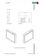
Page 107: ...MTUX IA 63 00 Installation Manual 107 Date 2017 02 1700 12 4 Dimensions in mm ...

Page 108: ...MTUX IA 63 00 Installation Manual 108 Date 2017 02 17 12 6 Connection USB to MDR 50 central connector see Connections 12 5 Functional Diagram ...

Page 109: ...onnected to an USB port on the rear side of the unit We recommend to connect the MT Video In Device to the rear USB on the left side with the longer tunnel The Easy mount must be modified a notch must be cut out to lead the USB cable through Please see pictures for the recommended placing which will not effect the stability and functionality of the Easy Mount Easy mount with marked notch front vie...

Page 110: ...MTUX IA 63 00 Installation Manual 110 Date 2017 02 17 Easy mount with marked notch bottom view Easy mount with marked notch front view detail turned 90 counter clockwise ...

Page 111: ...ionAir X ETSO USB connection Processible signals Composite Video FBAS RS 170 PAL NTSC Input 1 x FBAS composite video input 75 Ohm via BNC Cinch connection via BNC Cinch adapter possible Displaying Full screen in 4 3 format with max resolution 1024 x 768 pixels 13 2 Directions for use Usage via hotkey C on the frame keyboard C switch to video in C switch back to MFD screen with Moving Map functions...

Page 112: ...MTUX IA 63 00 Installation Manual 112 Date 2017 02 17 13 3 Dimensions in mm ...

Page 113: ...oses and Moving Terrain program resumes full screen It is now necessary to restart the unit to reread the new configuration 13 4 2 MT Camera Parameters Parameters in mtpro ini section CAMERA Note If this section is not in the file add it make sure you use squared brackets Parameter Possible values Description profile empty Generic PAL video source This is the factory default and the software assum...

Page 114: ...ionAir X ETSO Connection 1 VGA from external computer to MT VGA Input Device PN MTEX CA 15 00 Connection 2 Special USB cable to one of the direct USB ports of MT VisionAir X ETSO on the rear side 14 3 Prerequisites OS 13 5 for MT VisionAir X SW Version 6 0 or higher MT Camera must be enabled 14 4 Directions for use Usage via hotkey C on the frame keyboard normal keypress not hold C switch to VGA i...

Page 115: ...MTUX IA 63 00 Installation Manual 115 Date 2017 02 1700 14 5 Dimensions MT VGA Input Device in mm ...

Page 116: ... the left side with the longer tunnel The Easy mount must be modified a notch must be cut out to lead the USB cable through Please see pictures for the recommended placing which will not effect the stability and functionality of the Easy Mount 14 6 Installation diagram VON EINEM AUTODESK SCHULUNGSPRODUKT ERSTELLT 33 1 We recommend the usage of this USB port ...

Page 117: ...MTUX IA 63 00 Installation Manual 117 Date 2017 02 1700 Easy mount with marked notch bottom view Easy mount with marked notch front view detail turned 90 counter clockwise ...

Page 118: ...ack squares 16 1 1 No external dimmer connected If no external dimmer is connected the brightness actually goes to minimum analog input voltage is zero 15 1 2 External dimmer connected If external dimmer is connected then it directly controls the system brightness Note 1 NVG mode is not impacted Note 2 The manual brightness levels 1 to 5 work normally 15 1 3 Entries in mtpro ini for DIMMING Exampl...

Page 119: ...n Manual 119 Date 2017 02 1700 15 2 Wiring Voltage between Pin 31 and PIN 4 GND on the MDR50 central connector See Installation manual PN MTEX IA 62 02 page 42 43 Input voltage 0 28V 0V minimum brightness 28V maximum brightness ...

Page 120: ...with SP boards TT board units can be used directly To check board type use AUX SETUP VERSION VERSION 5 The Satphone must have a clear view of the sky or be connected to an external antenna 16 2 Usage NOTE The Iridium Satphone must be switched on manually during preflight and should be turned off manually as well after the flight The MT VisionAir X software cannot control the Satphone power No othe...

Page 121: ...nfirm the change press BACK to clear it NOTE 1 The tracking status and interval is remembered between sessions so that if it was ON on last shutdown it will start active on the next flight NOTE 2 Each successful position report transmits an Iridium SBD packet with a size of 16 bytes Failed transmission attempts are not charged This information can be used to estimate tracking costs according to th...

Page 122: ...or the phone may be switched off Satphone comm problem cable The Satphone was detected but the software does not get responses when sending commands Either the USB cable is not firmly connected or there is another hardware software condition which garbles the communication between the VisionAir and the phone In extreme cases could be due to strong electro magnetic interference especially if the US...

Page 123: ...ueue is full at the Iridium ground station Either the ground tracking software MT OPS Center is not configured correctly or it has not been run for a long time so that tracking mes sages have accumulated Iridium message error 12 This error should be reported to MT for VisionAir X diagnostic may also indicate a Satphone hard ware firmware fault Iridium error at gnd station Temporary or permanent er...

Page 124: ...ary overload 38 The phone is temporarily refusing to send SBD messages to lower the load on the Iridium network It is a built in feature of Iridium Satphones Traffic management period and should not harm normal operations Satphone hardware error 64 Possible hardware problem with the Satphone Band violation attempt to transmit outside permit ted frequency band Satphone hardware error 65 Possible ha...

Page 125: ...MTUX IA 63 00 Installation Manual 125 Date 2017 02 1700 INTENTIONALLY LEFT BLANK ...

Page 126: ...m Satphones 9555 9575 Restriction During voice calls SBD messages cannot be transmitted nor received and the software has no way to know beforehand if the pilot is dialing a phone number nor receiving a call The effect is that the RescueTrack control center will not see position reports during voice calls and will not know the reason 17 1 2 Contract with Iridium Provider for SBD Short Burst Data P...

Page 127: ...requisite Software version X 5 1 and higher on OS 13 The option must be enabled 17 2 2 Settings on the MT VisionAir X System 17 2 2 1 MTPRO INI How to work with mtpro ini Connect an USB keyboard Press SHIFT 1 or equivalent for to call the configuration text editor Edit the desired parameters When finished press CTRL X then Y to confirm and save the changes N will discard all changes The new config...

Page 128: ... VisionAir X will send a position update as soon as the pilot selects a new DCT destination Otherwise the standard time between position updates is 60 seconds 17 2 2 2 Setting of ITAS Module for Communication AUX SETUP DIAL UP Choose IRIDIUM TRANSCEIVER ANTENNA SYSTEM ITAS by pressing UP DOWN and confirm with USE This setting will be saved 17 2 2 3 How to Activate the Data Transfer to and from Res...

Page 129: ...ack status Frei auf Funk Frei auf Wache Einsatz übernommen Am Einsatzort Sprechwunsch Außer Dienst Patient übernommen Im Krankenhaus Ferry Flight GOTO DCT msgUP msgDN BACK in the background normal map screen 17 3 1 Description Left half Incoming news latest at the top Right half Standardized messages sent by the helicopter 17 3 2 Incoming Messages The last 5 incoming messages are displayed in the ...

Page 130: ...e info block in the main menu moving map is shown As soon as the pilot looks into the message with AUX MMS the symbol will be deleted in the info box The notice of the message is displayed on the moving map B L I N K I N G to increase attention 17 3 4 Selection of Standardized Status Messages Bezels 2 0 By pressing the corresponding key the message will turn cyan Automated sending together with th...

Page 131: ...02 1700 17 3 5 BACK Back to Main Menu Moving Map 17 3 6 Saving of Current Setting The tracking setting remains stored and will be activated immediately at system startup If the communication with the ITAS module is not given an error message appears ...

Page 132: ...X IA 63 00 Installation Manual 132 Date 2017 02 17 17 4 ITAS System Components and Connection 17 4 1 Technical Information for ITAS Test Cable 17 4 1 1 Data Sheet copyright Hirschmann Car Communication Inc ...

Page 133: ...Port on MT in Com3 on the MDR50 central connector Com Gnd 19 is to be connected to pin 26 29 MDR50 On Off Control activation pin pin 6 grey in M12 8 ITAS is to be connected to pin 5 External Power Source 8 32 VDC 5VDC optional Power Consumption 1 Amp max transmit 65mA Standby on off signal line Transient Protection SAE J1113 11 12 Reverse Voltage Protection 24V tested Note On Off control through p...

Page 134: ...MTUX IA 63 00 Installation Manual 134 Date 2017 02 17 17 4 1 3 Example Installation 17 4 1 4 Test Procedure AUX TRACK type MTITESTJ and start simulator AUX TRACK SIM ON ...

Page 135: ...ter in front of the last line and delete in front of the 2 last line COM port will not be blocked MT program will not start automatically reboot minicom b 19200 D dev ttyUSB2 opens COM3 with 19200 baud ati4 type in minicom answer should be IRIDIUM 9600 Family communication with modem established strg z x exit minicom nano xinitrc revert the in front of the last 2 last line and save reboot ...

Page 136: ...MTUX IA 63 00 Installation Manual 136 Date 2017 02 17 17 4 2 Technical Information for ITAS Module Copyright Hirschmann Car Communication Inc We accept no liability for errors ...

Page 137: ...MTUX IA 63 00 Installation Manual 137 Date 2017 02 1700 ...

Page 138: ...MTUX IA 63 00 Installation Manual 138 Date 2017 02 17 ...

Page 139: ...MTUX IA 63 00 Installation Manual 139 Date 2017 02 1700 INTENTIONALLY LEFT BLANK ...

Page 140: ...ck Moving Terrain with satellite telephone 18 2 1 Check satellite telephone antenna Check point Correct The distance between GPS antenna and satellite telephone an tenna is at least 1 3 m The Sat Tel antenna has optimal view about 180 to the sky The position of the satellite telephone antenna is suitable for recep tion Is it neither installed vertically nor installed vice versa Please inform yours...

Page 141: ...errain Check point Correct The UTC see Info Box is transmitted by GPS The correct telephone source is selected 18 3 Check Moving Terrain with UMTS Check point Correct Security PIN code deactivated with a cell phone The correct telephone source is selected 18 4 Check further Com Port connection s Check point Correct TCAD AUX TAS Sel Check TAS signal Avidyne OK FLARM OK Stormscope AUX Stormscope OK ...

Page 142: ...it special software required Arrangement of keys enables both presentations NVG Night vision goggles compatibility with special soft ware option Keyboard Silicone keypad with 36 alphanumeric keys 10 multi function keys ON OFF switch key to adjust screen luminance in 8 steps Gold plated contacts on both matrix and key sides Keys illuminated blue NVG compatible dimmed together with display luminance...

Page 143: ...Temperature high short time operation 50 C Temperature high operating 50 C Shock and g loading Operational Shock Test according to RTCADO 160F section 7 2 1 in X Y Z Axis Vibration Operational Vibration Test according to RTCA DO 160F section 8 8 3 Random Test Procedure for Category U2 Unknown Helicopter fixed wing fre quencies Mounting Easy Mount for panel or yoke side mounting Performed Operation...

Page 144: ...nels 50 max Positioning update rate 4 Hz High sensitivity 160 dBm Support DGPS WAAS EGNOS MSAS AssistNow Online 14 days Almanac data Base setting WGS 84 Dimensions W x H x D 49 mm x 23 mm x 81 mm Extension cable 4 line RS232 data cable with RX TX power ground Shielding Aluminium foil in combination with cop per mesh tin coated approx 90 covering Table 19 2 Technical specifications Fast Integral GP...

Page 145: ...versal FMS FLARM COM 3 1 Signal from FLARM only used if FLARM is com bined with Avidyne Ryan Protocol in TCAS TAS2SEL FLARM and mtpro ini COM 3 2 Serial port for ITAS modul Protocol set in mtpro ini COM 3 3 Serial port for Crossfill from Garmin no entry in mtpro ini Check possible conflict with TCAS combined COM 4 Stormscope WX 500 WX 670 Protocol set in mtpro ini Table 19 3 COM Ports assignment N...

Page 146: ...MTUX IA 63 00 Installation Manual 146 Date 2017 02 17 INTENTIONALLY LEFT BLANK ...

Reviews: