background image

I

Quick Start

Quick Start

Thank you for purchasing the MSI

®


Z370 GAMING PRO CARBON/ 

Z370 GAMING PRO CARBON AC


motherboard. This Quick Start 

section provides demonstration diagrams about how to install 

your computer. Some of the installations also provide video 

demonstrations. Please link to the URL to watch it with the web 

browser on your phone or tablet. You may have even link to the URL 

by scanning the QR code.

Kurzanleitung

Danke, dass Sie das MSI

®


Z370 GAMING PRO CARBON/ Z370 

GAMING PRO CARBON AC

 Motherboard gewählt haben. Dieser 

Abschnitt der Kurzanleitung bietet eine Demo zur Installation 

Ihres Computers. Manche Installationen bieten auch die 

Videodemonstrationen. Klicken Sie auf die URL, um diese 

Videoanleitung mit Ihrem Browser auf Ihrem Handy oder Table 

anzusehen. Oder scannen Sie auch den QR Code mit Ihrem Handy, 

um die URL zu öffnen.

Présentation rapide

Merci d

avoir choisi la carte mère MSI

®


Z370 GAMING PRO CARBON/ 

Z370 GAMING PRO CARBON AC

. Ce manuel fournit une rapide 

présentation avec des illustrations explicatives qui vous aideront à 

assembler votre ordinateur. Des tutoriels vidéo sont disponibles pour 

certaines étapes. Cliquez sur le lien fourni pour regarder la vidéo sur 

votre téléphone ou votre tablette. Vous pouvez également accéder au 

lien en scannant le QR code qui lui est associé.

Быстрый


старт

Благодарим


вас


за


покупку


материнской


платы

 MSI

®


Z370 

GAMING PRO CARBON/ Z370 GAMING PRO CARBON AC

В


этом


разделе


представлена


информация

которая


поможет


вам


при


сборке


комьютера

Для


некоторых


этапов


сборки


имеются


видеоинструкции

Для


просмотра


видео

необходимо


открыть


соответствующую


ссылку


в


веб

-

браузере


на


вашем


телефоне


или


планшете

Вы


также


можете


выполнить


переход


по


ссылке

путем


сканирования


QR-

кода

.

Summary of Contents for Z370 GAMING PRO CARBON

Page 1: ...nzusehen Oder scannen Sie auch den QR Code mit Ihrem Handy um die URL zu öffnen Présentation rapide Merci d avoir choisi la carte mère MSI Z370 GAMING PRO CARBON Z370 GAMING PRO CARBON AC Ce manuel fournit une rapide présentation avec des illustrations explicatives qui vous aideront à assembler votre ordinateur Des tutoriels vidéo sont disponibles pour certaines étapes Cliquez sur le lien fourni p...

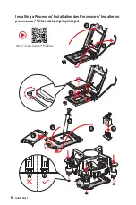
Page 2: ...II Quick Start 1 2 3 6 4 5 7 8 9 Installing a Processor Installation des Prozessors Installer un processeur Установка процессора https youtu be 4ce91YC3Oww ...

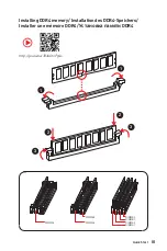
Page 3: ...I Quick Start Installing DDR4 memory Installation des DDR4 Speichers Installer une mémoire DDR4 Установка памяти DDR4 http youtu be T03aDrJPyQs DIMMB2 DIMMB2 DIMMB1 DIMMA2 DIMMA2 DIMMA2 DIMMA1 1 1 2 2 3 3 ...

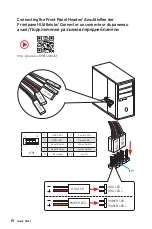
Page 4: ... LED POWER LED POWER LED Connecting the Front Panel Header Anschließen der Frontpanel Stiftleiste Connecter un connecteur du panneau avant Подключение разъемов передней панели http youtu be DPELIdVNZUI 1 2 10 9 JFP1 1 HDD LED 2 Power LED 3 HDD LED 4 Power LED 5 Reset Switch 6 Power Switch 7 Reset Switch 8 Power Switch 9 Reserved 10 No Pin ...

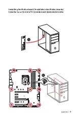
Page 5: ...V Quick Start Installing the Motherboard Installation des Motherboards Installer la carte mère Установка материнской платы 1 2 ...

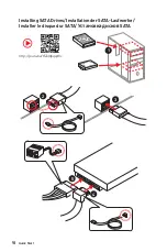
Page 6: ...VI Quick Start 1 2 3 4 5 Installing SATA Drives Installation der SATA Laufwerke Installer le disque dur SATA Установка дисков SATA http youtu be RZsMpqxythc ...

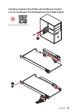
Page 7: ...VII Quick Start 1 2 3 4 5 6 Installing a Graphics Card Einbau der Grafikkarte Installer une carte graphique Установка дискретной видеокарты http youtu be mG0GZpr9w_A ...

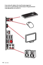
Page 8: ...VIII Quick Start Connecting Peripheral Devices Peripheriegeräte Connecter un périphérique anschliessen Подключение периферийных устройств ...

Page 9: ...IX Quick Start Connecting the Power Connectors Stromanschlüsse anschliessen Connecter les câbles du module d alimentation Подключение разъемов питания http youtu be gkDYyR_83I4 ATX_PWR1 CPU_PWR1 ...

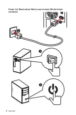
Page 10: ...X Quick Start 1 4 2 3 Power On Einschalten Mettre sous tension Включение питания ...

Page 11: ...Front Panel Connectors 21 CPU_PWR1 ATX_PWR1 Power Connectors 22 JUSB1 2 USB 2 0 Connectors 23 JUSB3 4 USB 3 1 Gen1 Connectors 23 CPU_FAN1 PUMP_FAN1 SYS_FAN1 4 Fan Connectors 24 JAUD1 Front Audio Connector 25 JCI1 Chassis Intrusion Connector 25 JTPM1 TPM Module Connector 26 JBAT1 Clear CMOS Reset BIOS Jumper 26 JRGB1 JRGB2 JRAINBOW1 RGB LED Connectors 27 JCORSAIR1 CORSAIR Connector 28 Onboard LEDs ...

Page 12: ...2 Contents OC Menu 36 Software Description 44 Installing Windows 10 44 Installing Drivers 44 Installing Utilities 44 ...

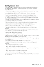
Page 13: ... computer before installation is completed This could cause permanent damage to the components as well as injury to the user y If you need help during any installation step please consult a certified computer technician y Always turn off the power supply and unplug the power cord from the power outlet before installing or removing any computer component y Keep this user guide for future reference ...

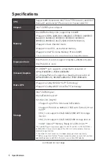
Page 14: ...1600 60Hz y 1x DisplayPort port supports a maximum resolution of 4096X2304 24Hz 3840X2160 60Hz 1920X1200 60Hz Multi GPU y Supports 2 Way NVIDIA SLI Technology y Supports 3 Way AMD CrossFire Technology Storage Intel Z370 Chipset y 6x SATA 6Gb s ports y 2x M 2 slots Key M Support up to PCIe 3 0 x4 and SATA 6Gb s Support PCIe 3 0 x4 NVMe U 2 SSD with Turbo U 2 Host Card M2_1 slot supports 2242 2260 2...

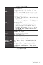
Page 15: ...USB ports 4 Type A ports on the back panel 4 ports available through the internal USB connectors 6x USB 2 0 High speed USB ports 2 Type A ports on the back panel 4 ports available through the internal USB connectors Audio y Realtek ALC1220 Codec y 7 1 Channel High Definition Audio y Supports S PDIF output LAN 1x Intel I219 V Gigabit LAN controller Wirsless LAN Bluetooth for Z370 GAMING PRO CARBON ...

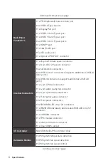
Page 16: ...1 connectors supports additional 4 USB 3 1 Gen1 ports y 2x USB 2 0 connectors supports additional 4 USB 2 0 ports y 1x 4 pin CPU fan connector y 1x 4 pin water pump fan connector y 4x 4 pin system fan connectors y 1x Front panel audio connector y 2x Front panel connectors y 2x 5050 RGB LED strip 12V connectors y 1x WS2812B Individually Addressable RGB LED strip 5V connector y 1x CORSAIR connector ...

Page 17: ...OL y RAMDISK y DPC LATENCY TUNER y FAST BOOT y X BOOST y DRAGON EYE y GAMING APP y SUPER CHARGER y MYSTIC LIGHT y GAMING LAN MANAGER y Nahimic Audio y Open Broadcaster Software OBS y TriDef VR SmartCam y SteelSeries Engine 3 y WTFast y CPU Z MSI GAMING y Intel Extreme Tuning Utility y Google Chrome Google Toolbar Google Drive y Norton Internet Security Solution This offer is valid for a limited pe...

Page 18: ... Fan Smart Fan Control y LED Mystic Light Mystic Light Extension RGB Mystic light SYNC EZ DEBUG LED Mystic Light Extension RAINBOW Corsair Extension y Protection M 2 Shield PCI E Steel Armor y Performance Multi GPU SLI Technology Multi GPU CrossFire Technology DDR4 Boost Lightning USB USB with Type A C Twin Turbo M 2 y Stability Military Class 5 Continued on next page ...

Page 19: ...nce GAMING HOTKEY GAMING MOUSE Control y BIOS Click BIOS 5 y Certification Quadro SLI Ready Quadro Ready SteelSeries Certified JCORSAIR1 Connector Specification Supporting CORSAIR RGB Products Maximum connection Lighting Node PRO RGB LED Strip 7 HD120 RGB Fan 6 SP120 RGB Fan 6 LL120 RGB Fan 5 ...

Page 20: ... Status Description Off No link Yellow Linked Blinking Data activity Speed LED Status Description Off 10 Mbps connection Green 100 Mbps connection Orange 1 Gbps connection LAN Port LED Status Table Audio Ports Configuration Audio Ports Channel 2 4 6 8 Center Subwoofer Out Rear Speaker Out Line In Side Speaker Out Line Out Front Speaker Out Mic In connected Blank empty ...

Page 21: ... volume or balance the right left side of the speakers that you plugged in front or rear panel by adjust the bar y Profiles toggles between profiles y Advanced Settings provides the mechanism to deal with 2 independent audio streams y Jack Status depicts all render and capture devices currently connected with your computer y Connector Settings configures the connection settings Auto popup dialog W...

Page 22: ... Rear I O Panel AUDIO INPUT Rear Front Side Center Subwoofer Audio jacks to headphone and microphone diagram Audio jacks to stereo speakers diagram Audio jacks to 7 1 channel speakers diagram AUDIO INPUT ...

Page 23: ...I_E3 PCI_E4 PCI_E5 PCI_E6 CPU Socket CPU_PWR1 JRGB2 ATX_PWR1 JUSB3 JUSB1 JUSB2 JBAT1 JUSB4 SATA 1 2 SATA 3 4 M2_1 M2_2 DIMMA1 DIMMA2 DIMMB1 DIMMB2 SYS_FAN1 SYS_FAN4 SYS_FAN3 JCI1 JSEL1 JRAINBOW1 SATA5 SATA6 CPU_FAN1 PUMP_FAN1 JCORSAIR1 JFP1 JFP2 DEMOLED1 JPWRLED1 SYS_FAN2 JAUD1 ...

Page 24: ...as formed a tight seal with the CPU before booting your system y Overheating can seriously damage the CPU and motherboard Always make sure the cooling fans work properly to protect the CPU from overheating Be sure to apply an even layer of thermal paste or thermal tape between the CPU and the heatsink to enhance heat dissipation y Whenever the CPU is not installed always protect the CPU socket pin...

Page 25: ...4GB or less for 32 bit Windows OS due to the memory address limitation Therefore we recommended that you to install 64 bit Windows OS if you want to install more than 4GB memory on the motherboard y Some memory may operate at a lower frequency than the marked value when overclocking due to the memory frequency operates dependent on its Serial Presence Detect SPD Go to BIOS and find the Memory Try ...

Page 26: ...s PCI_E4 PCIe 3 0 x8 CPU lanes PCI_E5 PCIe 3 0 x1 PCH lanes PCI_E6 PCIe 3 0 x4 PCH lanes x16 x8 x8 x8 x8 x4 Multiple graphics cards installation recommendation Important If you install a large and heavy graphics card you need to use a tool such as MSI Gaming Series Graphics Card Bolster to support its weight to prevent deformation of the slot ...

Page 27: ... user guide of your graphics card to make sure you meet all the system requirements To install SLI graphics cards 1 Turn off your computer and disconnect the power cord install two graphics cards into the PCI_E1 and PCI_E4 slots 2 Connect the two cards together using the SLI Bridge Connector 3 Connect all PCIe power connectors of the graphics cards 4 Reconnect the power cord power up the computer ...

Page 28: ...le to the USB connector on the card 3 Connect the other end of the USB cable to the USB 2 0 connector on the motherboard 4 Use the screw to secure the card 5 Screw the antennas tight to the RP SMA connectors on the Wi Fi Bluetooth PCIe card as shown Important Make sure all cables are properly connected Antennas USB cable USB 2 0 connector PCIe x1 slot Wi Fi Bluetooth PCIe card ...

Page 29: ... module into the M 2 slot at a 30 degree angle 5 Put the screw in the notch on the trailing edge of your M 2 module and tighten it into the base screw 4 Using M 2 shield We provide the M 2 shield on the M2_1 slot to help dissipate heat away from the M 2 module Before installing the M 2 module for the first time you need to remove the screw lift the cover and remove the protective film and the roun...

Page 30: ...g transmission otherwise y SATA cables have identical plugs on either sides of the cable However it is recommended that the flat connector be connected to the motherboard for space saving purposes M 2 SATA combination table Slot Available SATA connectors M2_1 PCIe SATA PCIe SATA PCIe SATA M2_2 PCIe PCIe SATA SATA SATA1 SATA2 SATA3 SATA4 SATA5 SATA6 SATA M 2 SATA SSD PCIe M 2 PCIe SSD available una...

Page 31: ... SSD 1xM 2 SATA SSD 5xSATA HDDs 2xM 2 SATA SSDs 4xSATA HDDs 2xM 2 PCIe SSDs 4xSATA HDDs 1xM 2 PCIe SSD 6xSATA HDDs SATA6 SATA6 JFP1 JFP2 Front Panel Connectors These connectors connect to the switches and LEDs on the front panel 1 2 10 9 JFP1 1 HDD LED 2 Power LED 3 HDD LED 4 Power LED 5 Reset Switch 6 Power Switch 7 Reset Switch 8 Power Switch 9 Reserved 10 No Pin 1 JFP2 1 Speaker 2 Buzzer 3 Buzz...

Page 32: ...Res 9 5VSB 21 5V 10 12V 22 5V 11 12V 23 5V 12 3 3V 24 Ground 5 4 1 8 CPU_PWR1 1 Ground 5 12V 2 Ground 6 12V 3 Ground 7 12V 4 Ground 8 12V Important Make sure that all the power cables are securely connected to a proper ATX power supply to ensure stable operation of the motherboard CPU_PWR1 ATX_PWR1 Power Connectors These connectors allow you to connect an ATX power supply ...

Page 33: ...B3_RX_DN 9 USB2 0 19 Power 10 NC 20 No Pin Important Note that the Power and Ground pins must be connected correctly to avoid possible damage JUSB1 2 USB 2 0 Connectors These connectors allow you to connect USB 2 0 ports on the front panel 1 2 10 9 1 VCC 2 VCC 3 USB0 4 USB1 5 USB0 6 USB1 7 Ground 8 Ground 9 No Pin 10 NC Important y Note that the VCC and Ground pins must be connected correctly to a...

Page 34: ...ow to adjust the fan connector to PWM or DC Mode PWM Mode pin definition 1 Ground 2 12V 3 Sense 4 Speed Control Signal DC Mode pin definition 1 Ground 2 Voltage Control 3 Sense 4 NC Default PWM Mode fan connectors Default DC Mode fan connectors Switching fan mode and adjusting fan speed You can switch between PWM mode and DC mode and adjust fan speed in BIOS HARDWARE MONITOR Select PWM mode or DC ...

Page 35: ... intrusion detector 1 Connect the JCI1 connector to the chassis intrusion switch sensor on the chassis 2 Close the chassis cover 3 Go to BIOS Settings Security Chassis Intrusion Configuration 4 Set Chassis Intrusion to Enabled 5 Press F10 to save and exit and then press the Enter key to select Yes 6 Once the chassis cover is opened again a warning message will be displayed on screen when the compu...

Page 36: ...ity platform manual for more details and usages JBAT1 Clear CMOS Reset BIOS Jumper There is CMOS memory onboard that is external powered from a battery located on the motherboard to save system configuration data If you want to clear the system configuration set the jumpers to clear the CMOS memory Keep Data default Clear CMOS Reset BIOS Resetting BIOS to default values 1 Power off the computer an...

Page 37: ...orts 5050 RGB LED strips 12V G R B with the maximum power rating of 3A 12V y The JRAINBOW1 connector supports WS2812B Individually Addressable RGB LED strips 5V Data Ground with the maximum power rating of 3A 5V y Please keeping the LED strip shorter than 2 meters to prevent dimming y Always turn off the power supply and unplug the power cord from the power outlet before installing or removing the...

Page 38: ...1 2 3 4 5 6 Any fan not connected in series will break communication and the RGB LED lighting function will not work y Quantity of RGB LED Fans or RGB LED Lighting PRO strips supported may differ between models Please refer to the motherboard specification y CORSAIR RGB LED Fan and CORSAIR Lighting Node PRO can t be used at the same time 1 JCORSAIR1 1 5V 2 Data 3 Ground JCORSAIR1 connector JCORSAI...

Page 39: ...cates the XMP Extreme Memory Profile mode is enabled PCIe x16 slot LEDs These LED indicate the PCIe x16 slots status CPU indicates CPU is not detected or fail DRAM indicates DRAM is not detected or fail VGA indicates GPU is not detected or fail BOOT indicates the booting device is not detected or fail LED Color PCIe slot status Red x16 mode White x8 x4 x1 mode ...

Page 40: ...e installed LED light effect demonstration components These components are used by retailers to demonstrate onboard LED light effects JPWRLED1 LED power input DEMOLED1 Change LED light effects JSEL1 Short press DEMOLED1 will change color Open press DEMOLED1 will change effects ...

Page 41: ...owing methods to enter BIOS setup y Press Delete key when the Press DEL key to enter Setup Menu F11 to enter Boot Menu message appears on the screen during the boot process y Use MSI FAST BOOT application Click on GO2BIOS button and choose OK The system will reboot and enter BIOS setup directly Click on GO2BIOS Function key F1 General Help F2 Add Remove a favorite item F3 Enter Favorites menu F4 E...

Page 42: ...he BIOS Setup during POST 2 Insert the USB flash drive that contains the update file into the computer 3 Select the M FLASH tab and click on Yes to reboot the system and enter the flash mode 4 Select a BIOS file to perform the BIOS update process 5 After the flashing process is 100 completed the system will reboot automatically Updating the BIOS with Live Update 6 Before updating Make sure the LAN...

Page 43: ...rcle to select the X M P profile This switch will only be available if the X M P supported memory module is installed y Setup Mode switch press this tab or the F7 key to switch between Advanced mode and EZ mode y Screenshot click on this tab or the F12 key to take a screenshot and save it to USB flash drive FAT FAT32 format only y Search click on this tab or the Ctrl F keys and the search page wil...

Page 44: ...Hardware Monitor menu that allows you to manually control the fan speed by percentage y Favorites press the Favorites tab or the F3 key to enter Favorites menu It allows you to create personal BIOS menu where you can save and access favorite frequently used BIOS setting items Default HomePage allows you to select a BIOS menu e g SETTINGS OC etc as the BIOS home page Favorite1 5 allows you to add t...

Page 45: ...o the descriptions of EZ Mode Overview section y BIOS menu selection the following options are available SETTINGS allows you to specify the parameters for chipset and boot devices OC allows you to adjust the frequency and voltage Increasing the frequency may get better performance M FLASH provides the way to update BIOS with a USB flash drive OC PROFILE allows you to manage overclocking profiles H...

Page 46: ... BIOS setup Note We use as the symbol for the OC settings of Expert mode f Beta Runner Disabled Beta function or feature for DIY attempt only f CPU Ratio Apply Mode All Core Sets applied mode for CPU ratio This item only appears when a CPU that supports Turbo Boost is installed All Core Activate the CPU Ratio field All CPU cores will run the same CPU ratio that be set in CPU Ratio Per Core Activat...

Page 47: ...usted Ring Frequency Shows the adjusted Ring frequency Read only f GT Ratio Auto Sets the integrated graphics ratio The valid value range depends on the installed CPU f Adjusted GT Frequency Shows the adjusted integrated graphics frequency Read only f Misc Setting Press Enter or key to open or close the following 3 items related to CPU features fEIST Enabled Enables or disables the Enhanced Intel ...

Page 48: ...ct a profile of memory module for overclocking the memory This item will be available when the memory modules that support X M P is installed f DRAM Reference Clock Auto Sets the DRAM reference clock The valid value range depends on the installed CPU This item appears when a CPU that supports this adjustment is installed f DRAM Frequency Auto Sets the DRAM frequency Please note the overclocking be...

Page 49: ...to Sets the voltage limit for CPU under voltage protection If set to Auto BIOS will configure this setting automatically Higher voltage provides less protection and may damage the system fCPU Over Current Protection Auto Sets the current limit for CPU over current protection If set to Auto BIOS will configure this setting automatically fCPU Switching Frequency Auto Sets the PWM working speed to stab...

Page 50: ...s or disables the CPU GT VRM for over temperature protection The CPU GT frequency may be throttled when VRM temperature over the specified value f CPU Core GT Voltage Mode Auto Sets the CPU Core GT voltage mode Auto This setting will be configured automatically by BIOS Adaptive Mode Sets the adaptive voltage automatically for optimizing the system performance Override Mode Allows you to set the vol...

Page 51: ...isplays all the settings and timings of installed memory You can also access this information menu at any time by pressing F5 fDIMMx Memory SPD Press Enter to enter the sub menu The sub menu displays the information of installed memory Read only f CPU Features Press Enter to enter the sub menu fHyper Threading Enabled Intel Hyper Threading technology treats the multi cores inside the processor as ...

Page 52: ...d tuning the performance to the specific application Disabled Enables the requested cache line only fCPU AES Instructions Enabled Enables or disables the CPU AES Advanced Encryption Standard New Instructions support This item appears when a CPU supports this function fIntel Adaptive Thermal Monitor Enabled Enables or disables the Intel adaptive thermal monitor function to protect the CPU from over...

Page 53: ...appears when a CPU that support Turbo Boost is installed Enabled Enables this function to boost CPU performance automatically over specification when system request the highest performance state Disabled Disables this function fLong Duration Power Limit W Auto Sets the long duration TDP power limit for CPU in Turbo Boost mode fLong Duration Maintained s Auto Sets the maintaining time for Long dura...

Page 54: ...I Driver Disc into your optical drive 3 The installer will automatically appear and it will find and list all necessary drivers 4 Click Install button 5 The software installation will then be in progress after it has finished it will prompt you to restart 6 Click OK button to finish 7 Restart your computer Installing Utilities Before you install utilities you must complete drivers installation 1 I...

Page 55: ...1 Connecteurs d alimentation 23 JUSB1 2 Connecteurs USB 2 0 24 JUSB3 4 Connecteurs USB 3 1 Gen1 24 CPU_FAN1 PUMP_FAN1 SYS_FAN1 4 Connecteurs pour ventilateurs 25 JAUD1 Connecteur audio avant 26 JCI1 Connecteur intrusion châssis 26 JTPM1 Connecteur de module TPM 27 JBAT1 Cavalier Clear CMOS Réinitialisation BIOS 27 JRGB1 JRGB2 JRAINBOW1 Connecteurs LED RGB 28 JCORSAIR1 Connecteur CORSAIR 29 Indicat...

Page 56: ...2 Table des matières OC Menu menu overclocking 37 Informations sur les logiciels 46 Installer Windows 10 46 Installer les pilotes 46 Installer les utilitaires 46 ...

Page 57: ...xés sur la carte mère ou ailleurs dans le boîtier de l ordinateur y Ne démarrez pas l ordinateur avant d avoir terminé l installation Ceci peut endommager les composants ou vous blesser y Si vous avez besoin d aide pendant l installation veuillez consulter un technicien informatique certifié y Avant d installer les composants d ordinateur veuillez toujours mettre hors tension et débrancher le cord...

Page 58: ... un buffered y Support Intel Extreme Memory Profile XMP Veuillez vous référer au site www msi com pour plus d informations sur la mémoire compatible Slots d extension y 3 x slots PCIe 3 0 x16 support les modes x16 x0 x4 x8 x8 x4 y 3 x slots PCIe 3 0 x1 Sorties vidéo intégrées y 1 x port HDMI supportant une résolution maximum de 4096x2160 30Hz 2560x1600 60Hz y 1 x port DisplayPort supportant une ré...

Page 59: ... Intel Optane veuillez vous assurer d avoir mis à jour les pilotes et le BIOS avec la dernière version disponible sur le site officiel MSI RAID Chipset Intel Z370 y Support des architectures RAID 0 RAID 1 RAID 5 et RAID 10 pour les périphériques de stockage SATA y Support des architectures RAID 0 et RAID1 pour les périphériques de stockage M 2 PCIe La configuration RAID du SSD PCIe M 2 peut être c...

Page 60: ...e dans le slot M2_3 M 2 Touche E y Support Wi Fi 802 11 a b g n ac double bande 2 4GHz 5GHz jusqu à la vitesse de 867 Mbps y Support Dual Mode Bluetooth 2 1 2 1 EDR 3 0 4 0 BLE 4 2 Connecteurs sur le panneau arrière y 1 x port clavier souris PS 2 y 2 x ports USB 2 0 Type A y 1 x port DisplayPort y 1 x port USB 3 1 Gen2 Type A y 1 x port USB 3 1 Gen2 Type C y 4 x ports USB 3 1 Gen1 Type A y 1 x por...

Page 61: ... audio avant y 2 x connecteurs de panneau avant y 2 x connecteurs pour ruban LED RGB de type 5050 sortie 12V y 1 x connecteur pour ruban LED RGB WS2812B adressables individuellement sortie 5V y 1 x connecteur CORSAIR y 1 x connecteur de module TPM y 1 x connecteur intrusion châssis y 1 x cavalier Clear CMOS Contrôleur E S Contrôleur NUVOTON NCT6795 Moniteur système y Détection de la température du...

Page 62: ...YSTIC LIGHT y GAMING LAN MANAGER y Nahimic Audio y Open Broadcaster Software OBS y TriDef VR et SmartCam y SteelSeries Engine 3 y WTFast y CPU Z MSI GAMING y Intel Extreme Tuning Utility y Google Chrome Google Toolbar et Google Drive y Norton Internet Security Solution Cette fonctionnalité dépend d une offre limitée dans le temps Veuillez vous référer au site www msi com pour plus d informations S...

Page 63: ...la pompe Contrôle des ventilateurs y LED Mystic Light Mystic Light Extension RGB Mystic light SYNC EZ DEBUG LED Mystic Light Extension RAINBOW Corsair Extension y Protection M 2 Shield Steel Armor PCI E y Performance Technologie Multi GPU SLI Technologie Multi GPU CrossFire DDR4 Boost Lightning USB Port USB de type A et C Twin Turbo M 2 y Stabilité Military Class 5 Suite du tableau sur la page sui...

Page 64: ...HOTKEY Contrôle de la souris GAMING y BIOS Click BIOS 5 y Certification Quadro SLI Ready Quadro Ready SteelSeries Certifié Spécifications du connecteur JCORSAIR1 Produits CORSAIR à LED RGB supportés Connexion maximale Ruban LED RGB Lighting Node PRO 7 Ventilateur RGB HD120 6 Ventilateur RGB SP120 6 Ventilateur RGB LL120 5 ...

Page 65: ...onnexion Jaune Connexion correcte Clignote Activité en cours LED indiquant la vitesse Etat Description Eteint Débit de 10 Mbps Vert Débit de 100 Mbps Orange Débit de 1 Gbps Tableau explicatif de l état de la LED du port LAN Configuration des ports audio Ports Audio Canal 2 4 6 8 Sortie centre Caisson de basse Sortie audio haut parleur arrière Entrée Ligne Sortie audio haut parleur côté Sortie Lign...

Page 66: ... le son gauche droite des haut parleurs branchés sur le panneau avant ou derrière en ajustant la barre de volume y Profils bascule entre les profils y Paramètres avancés fournit le mécanisme pour gérer deux flux audio indépendants y Etat des prises Jack présente tous les périphériques de diffusion et de capture connectés à votre ordinateur y Paramètres du connecteur configure les paramètres de con...

Page 67: ...t Side Center Subwoofer Ilustration de l utilisation des ports audio dédiés au casque et au microphone Ilustration de l utilisation du port audio dédié aux haut parleurs Ilustration de l utilisation des ports audio dédiés aux haut parleurs 7 1 AUDIO INPUT ...

Page 68: ...1 PCI_E3 PCI_E4 PCI_E5 PCI_E6 Socket processeur CPU_PWR1 JRGB2 ATX_PWR1 JUSB3 JUSB1 JUSB2 JBAT1 JUSB4 SATA 1 2 SATA 3 4 M2_1 M2_2 DIMMA1 DIMMA2 DIMMB1 DIMMB2 SYS_FAN1 SYS_FAN4 SYS_FAN3 JCI1 JSEL1 JRAINBOW1 SATA5 SATA6 CPU_FAN1 PUMP_FAN1 JCORSAIR1 JFP1 JFP2 DEMOLED1 JPWRLED1 SYS_FAN2 JAUD1 ...

Page 69: ... la surchauffe Assurez vous d appliquer une couche de pâte thermique ou adhésif thermique entre le processeur et le système de refroidissement afin d améliorer la dissipation de la chaleur y Quand le processeur n est pas installé protégez toujours les broches de l emplacement du processeur avec le couvercle dédié y Si vous avez achetez un processeur indépendamment du ventilateur veuillez vous réfé...

Page 70: ...a limitation de mémoire Par conséquent il est recommandé d installer le système d exploitation Windows 64 bit si vous voulez installer une mémoire de plus de 4 Go sur la carte mère y Certaines mémoires peuvent fonctionner à une fréquence réduite par rapport à la valeur indiquée lors de l overclocking car la fréquence d opération de mémoire dépend du Serial Presence Detect SPD Rendez vous sur le BI...

Page 71: ...CI_E4 PCIe 3 0 x8 CPU lignes PCI_E5 PCIe 3 0 x1 PCH lignes PCI_E6 PCIe 3 0 x4 PCH lignes x16 x8 x8 x8 x8 x4 Installation recommandée pour une configuration multi GPU Important Si vous installez une carte graphique lourde il vous faut utiliser un outil comme la barre de support MSI Gaming Series pour supporter son poids et pour éviter la déformation du slot ...

Page 72: ... de votre carte graphique afin de parfaitement répondre à la demande du système Pour installer les cartes graphiques en SLI 1 Eteignez votre ordinateur et déconnectez le cordon d alimentation Installez deux cartes graphiques dans les slots PCI_E1 et PCI_E4 2 Connectez les deux cartes graphiques avec un pont SLI 3 Reliez tous les connecteurs d alimentation PCIe des cartes graphiques 4 Reconnectez l...

Page 73: ...r USB de la carte WiFi Bluetooth 3 Connectez l autre extrémité du câble USB au connecteur USB 2 0 de la carte mère 4 Utilisez une vis pour fixer la carte 5 Vissez fermement les antennes aux connecteurs RP SMA sur la carte PCIe Wi Fi Bluetooth comme illustré ici Important Assurez vous que tous les câbles sont correctement connectés Antennes Câble USB Connecteur USB 2 0 slot PCIe x1 Carte PCIe Wi Fi...

Page 74: ...ositionnez la vis dans l encoche située sur le bord du module M 2 et fixez la dans la vis de base 4 Vidéo de démonstration Référez vous à la vidéo d instruction sur l utilisation de la protection M 2 Shield https youtu be NwtQBpkUazs Utilisation de la protection M 2 Shield Nous fournissons une protection pour le slot M2_1 appelée M 2 Shield Cette protection permet de mieux dissiper la chaleur du m...

Page 75: ...rte de données pendant la transmission y Les câbles SATA disposent de prises identiques sur chaque côté Néanmoins il est recommandé de connecter la prise plate sur la carte mère pour un gain d espace Tableau de combinaison M 2 et SATA Slot Connecteurs SATA disponibles M2_1 PCIe SATA PCIe SATA PCIe SATA M2_2 PCIe PCIe SATA SATA SATA1 SATA2 SATA3 SATA4 SATA5 SATA6 SATA M 2 SATA SSD PCIe M 2 PCIe SSD...

Page 76: ... x SSDs M 2 SATA 4 x disques durs SATA 2 x SSDs M 2 PCIe 4 x disques durs SATA 1 x SSD M 2 PCIe 6 x disques durs SATA SATA6 SATA6 JFP1 JFP2 Connecteurs de panneau avant Ces connecteurs se lient aux interrupteurs et indicateurs LED du panneau avant 1 2 10 9 JFP1 1 HDD LED 2 Power LED 3 HDD LED 4 Power LED 5 Reset Switch 6 Power Switch 7 Reset Switch 8 Power Switch 9 Reserved 10 No Pin 1 JFP2 1 Spea...

Page 77: ...21 5V 10 12V 22 5V 11 12V 23 5V 12 3 3V 24 Ground 5 4 1 8 CPU_PWR1 1 Ground 5 12V 2 Ground 6 12V 3 Ground 7 12V 4 Ground 8 12V Important Veuillez vous assurer que tous les câbles d alimentation sont branchés aux connecteurs adéquats afin garantir une opération stable de la carte mère CPU_PWR1 ATX_PWR1 Connecteurs d alimentation Ces connecteurs vous permettent de relier une alimentation ATX ...

Page 78: ...No Pin Important Notez que les câbles d alimentation et de terre doivent être branchés correctement afin d éviter d endommager la carte JUSB1 2 Connecteurs USB 2 0 Ces connecteurs vous permettent de relier des ports USB 2 0 sur le panneau avant 1 2 10 9 1 VCC 2 VCC 3 USB0 4 USB1 5 USB0 6 USB1 7 Ground 8 Ground 9 No Pin 10 NC Important y Notez que les broches VCC et Terre doivent être branchées cor...

Page 79: ...ur en mode PWM ou mode DC Définition des broches en mode PWM 1 Ground 2 12V 3 Sense 4 Speed Control Signal Définition des broches en mode DC 1 Ground 2 Voltage Control 3 Sense 4 NC Connecteurs pour ventilateurs en mode PWM par défaut Connecteurs pour ventilateurs en mode DC par défaut Basculer entre les modes des ventilateurs et ajuster la vitesse Vous pouvez alterner entre le mode PWM et le mode ...

Page 80: ...vercle du boîtier 3 Allez dans le BIOS SETTINGS Réglages Security Sécurité Chassis Intrusion Configuration Configuration intrusion châssis 4 Réglez Chassis Intrusion intrusion châssis sur Enabled Activé 5 Appuyez sur F10 pour sauvegarder et quitter Ensuite appuyez sur la touche Enter Entrée pour choisir Yes Oui 6 Désormais si le boîtier du PC est ouvert quand l ordinateur est allumé vous recevrez ...

Page 81: ...S Une mémoire CMOS est intégrée et est alimentée en externe par une batterie située sur la carte mère afin de conserver les données de configuration système Si vous souhaitez nettoyer la configuration système placez le cavalier sur Effacer CMOS de manière à nettoyer la mémoire CMOS Conserver les données défaut Effacer CMOS Réinitialiser BIOS Réinitialiser le BIOS aux valeurs par défaut 1 Eteignez ...

Page 82: ...nce nominale maximale de 3A 12V y Le connecteur JRAINBOW1 supporte des rubans LED RGB WS2812B adressables individuellement 5V Data Ground avec une puissance nominale maximale de 3A 5V y Veuillez garder la longueur du ruban LED inférieure à 2 mètres pour éviter la gradation des couleurs y Avant d installer ou de retirer le ruban LED veillez à toujours éteindre l alimentation et à débrancher le câbl...

Page 83: ...n est pas connecté en série interrompra la communication et la fonction de rétroéclairage LED RGB ne fonctionnera pas y Le nombre de ventilateurs LED RGB ou de rubans CORSAIR Lightning Node Pro supportés peut varier selon le modèle Veuillez vous référer aux spécifications de la carte mère y Le ventilateur LED RGB de marque Corsair et le ruban CORSAIR Lighting Node PRO peuvent être utilisés en même...

Page 84: ...é Indicateurs LED du slot PCIe x16 Ces LED indiquent l état des slots PCIe x16 CPU indique que le CPU n est pas détecté ou que son initialisation a échoué DRAM indique que la mémoire DRAM n est pas détectée ou que son initialisation a échoué VGA indique que le GPU n est pas détecté ou que son initialisation a échoué BOOT indique que le périphérique de démarrage n est pas détecté ou que son initial...

Page 85: ...s de lumière des indicateurs LED Ces connecteurs sont utilisés par les revendeurs pour faire une démonstration des effets de lumière des indicateurs LED JPWRLED1 Indicateur LED de l entrée d alimentation DEMOLED1 Modifie les effets de lumière des indicateurs LED JSEL1 Court Modifie la couleur en appuyant sur DEMOLED1 Ouvrir Modifie les effets en appuyant sur DEMOLED1 ...

Page 86: ...Pendant le démarrage lorsqu apparaît le message Press DEL key to enter Setup Menu F11 to enter Boot Menu sur l écran veuillez appuyer sur la touche Suppr y Quand l ordinateur est déjà en marche vous pouvez utiliser l application MSI FAST BOOT Cliquez sur le bouton GO2BIOS puis sur OK Le système redémarre et entre dans l interface Setup du BIOS Cliquez sur GO2BIOS Touches de fonction F1 Aide généra...

Page 87: ...1 Appuyez sur la touche Suppr pour entrer dans l interface Setup du BIOS pendant le processus de POST 2 Connectez le lecteur Flash USB contenant le profil à l ordinateur 3 Choisissez l onglet M FLASH et cliquez sur Yes Oui pour redémarrer le système et entrer dans le mode Flash 4 Choisissez un profil BIOS pour commencer la mise à jour du BIOS 5 Une fois la mise à jour terminée le système redémarre...

Page 88: ...tème y Interrupteur XMP cliquez sur le cercle intérieur pour activer ou désactiver le profil XMP Extreme Memory Profile Cliquez sur le cercle extérieur pour choisir le profil XMP Cet interrupteur est seulement disponible si le profil XMP supporte le module de mémoire installé y Interrupteur de modes de réglages appuyez sur ce menu ou la touche F7 pour commuter entre le mode avancé et le mode simpl...

Page 89: ...Flash qui fournit la méthode de mise à jour BIOS à l aide d un disque flash USB y Moniteur de matériel cliquez sur ce bouton pour faire apparaître le menu Moniteur de matériel qui vous permet de contrôler manuellement la vitesse des ventilateurs y Favoris appuyez sur l onglet Favoris ou appuyez sur la touche F3 pour entrer dans le menu Favoris Il vous permet de créer un menu BIOS personnalisé où v...

Page 90: ... de périphérique démarrage veuillez vous référer à la partie EZ mode pour plus de précision y Sélection du menu BIOS les options suivantes sont disponibles SETTINGS Réglages permet de personnaliser les paramètres du chipset et du démarrage des périphériques OC permet d ajuster la fréquence et la tension L augmentation de la fréquence peut améliorer les performances M FLASH permet de mettre le BIOS...

Page 91: ...sons le symbole pour indiquer les réglages OC du mode Expert f Beta Runner Disabled Les fonctionnalités de la version bêta sont fournies pour que l utilisateur les teste lui même f CPU Ratio Apply Mode All Core Règle le mode d application en cours pour le ratio ou multiplicateur du processeur Ce menu n apparaît que si le processeur installé est compatible avec Turbo Boost All Core Active le paramè...

Page 92: ... modifiée Fonctionne en lecture seule f GT Ratio Auto Règle le ratio de la puce graphique intégrée La gamme de valeur valides dépend du processeur installé f Adjusted GT Frequency Montre la fréquence de la puce graphique intégrée modifiée Fonctionne en lecture seule f Misc Setting Appuyez sur les touches Entrée et ou pour ouvrir ou fermer les 3 paramètres suivants relatifs aux fonctionnalités du p...

Page 93: ...quence de base paramétrée immédiatement f Extreme Memory Profile X M P Disabled La technologie d overclocking X M P Extreme Memory Profile permet un overclocking par l intermédiaire du module de mémoire Activez la technologie XMP ou sélectionnez un profil de module de mémoire pour overclocker la mémoire Ce menu est seulement disponible si vous disposez de modules de mémoire prenant en charge la te...

Page 94: ...nnellement à la charge du processeur Une valeur plus élevée peut entraîner une tension plus élevée et de bonnes performances d overclocking mais augmentera la température du processeur et du module de régulation de tension VRM Mis en Auto le BIOS configure ce réglages automatiquement fCPU Over Voltage Protection Auto Définit une limite de tension pour la protection contre la surtension du CPU En Au...

Page 95: ...uency Auto Définit la vitesse de fonction du PWM pour stabiliser la tension du CPU GT et minimiser minimize la gamme d ondulation L augmentation de la vitesse de fonction PWM élève la température MOSFET Il est nécessaire alors de disposer d une solution de refroidissement adéquate pour MOSFET avant d augmenter cette valeur En Auto le BIOS configure automatiquement ce réglage fCPU GT VRM Over Tempera...

Page 96: ...seur installé Vous pouvez également accéder à ce sous menu à tout moment en appuyant sur la touche F4 Fonctionne en lecture seule fCPU Technology Support Appuyez sur la touche Entrée pour accéder au sous menu Ce sous menu affiche les principales fonctions et technologies prises en charge par le processeur installé Fonctionne en lecture seule f MEMORY Z Appuyez sur la touche Entrée pour accéder au s...

Page 97: ...re Prefetcher Enabled Active ou désactive le prefetcher matériel MLC Streamer prefetcher Enabled Permet au prefetcher matériel d acquérir automatiquement les données et les instructions dans le cache L2 de la mémoire pour ajuster les performances du processeur Disabled Désactive le prefetcher matériel fAdjacent Cache Line Prefetch Enabled Active ou désactive le prefetcher matériel du processeur ML...

Page 98: ...ock Enabled Verrouille ou déverrouille la fonction MSR 0xE2 15 CFG lock bit Enabled Verrouille le CFG lock bit Disabled Déverrouille le CFG lock bit fEIST Enabled Active ou désactive Enhanced Intel SpeedStep Technology Ce menu apparaît lorsque OC Explore Mode est mis en Normal Enabled Active la technologie EIST pour ajuster la tension du processeur et de la fréquence du cœur de manière dynamique C...

Page 99: ...leur est supérieure à une valeur définie le processeur réduit automatiquement la fréquence du cœur pour réduire la consommation d énergie fFCLK Frequency Auto Définit la fréquence du signal d horloge pour mettre sous en tension tôt Une fréquence FCLK réduite peut vous aider à conserver une fréquence de base élevée fDMI Link Speed Auto Définit la vitesse de l interface DMI Direct Media Interface qui r...

Page 100: ... Disc dans le lecteur optique 3 L outil d installation apparaît automatiquement Il trouvera et listera tous les pilotes dont vous avez besoin 4 Cliquez sur le bouton Install 5 L installation des pilotes commence Une fois terminée il vous sera demandé de redémarrer 6 Cliquez sur le bouton OK pour terminer 7 Redémarrez votre ordinateur Installer les utilitaires Avant d installer les utilitaires il f...

Page 101: ...panel Anschlüsse 22 CPU_PWR1 ATX_PWR1 Stromanschlüsse 23 JUSB1 2 USB 2 0 Anschlüsse 24 JUSB3 4 USB 3 1 Gen1 Anschlüsse 24 CPU_FAN1 PUMP_FAN1 SYS_FAN1 4 Stromanschlüsse für Lüfter 25 JAUD1 Audioanschluss des Frontpanels 26 JCI1 Gehäusekontaktanschluss 26 JTPM1 TPM Anschluss 27 JBAT1 Clear CMOS Steckbrücke Reset BIOS 27 JRGB1 JRGB2 JRAINBOW1 RGB LED Anschlüsse 28 JCORSAIR1 CORSAIR Anschluss 29 Onboa...

Page 102: ...2 Inhalt OC Menü 37 Softwarebeschreibung 46 Installation von Windows 10 46 Installation von Treibern 46 Installation von Utilities 46 ...

Page 103: ...puter nicht bevor die Installation abgeschlossen ist Dies könnte permanente Schäden an den Komponenten sowie zu das Verletzung des Benutzers verursachen y Sollten Sie Hilfe bei der Installation benötigen wenden Sie sich bitte an einen zertifizierten Computer Techniker y Schalten Sie die Stromversorgung aus und ziehen Sie das das Stromkabel ab bevor Sie jegliche Computer Komponente ein und ausbauen...

Page 104: ... ungepufferte Speicher y Unterstützt Intel Extreme Memory Profile XMP Weitere Informationen zu kompatiblen Speicher finden Sie unter http www msi com Erweiterung anschlüsse y 3x PCIe 3 0 x16 Steckplätze unterstützt x16 x0 x4 x8 x8 x4 Modi y 3x PCIe 3 0 x1 Steckplätze Onboard Grafik y 1x HDMI Anschluss Unterstützung einer maximalen Auflösung von 4096x2160 30Hz 2560x1600 60Hz y 1x DisplayPort Anschl...

Page 105: ...rstützen maximal 1x M 2 PCIe SSD 1x M 2 SATA SSD 5x SATA HDDs Auf Seite 21 finden Sie eine Anleitung für verschiedene M 2 Steckplätze Kombinationstabelle Die Turbo U 2 Hostkarte ist im Lieferumfang nicht enthalten bitte separat kaufen Bevor Sie Intel Optane Speichermodule verwenden stellen Sie bitte über Downloads von der MSI Website sicher dass die Treiber und das BIOS auf dem neuesten Stand sind...

Page 106: ...Audio y Realtek ALC1220 Codec y 7 1 Kanal HD Audio y Unterstützt S PDIF Ausgang LAN 1x Intel I219 V Gigabit LAN Controller Wirsless LAN Bluetooth nur für Z370 GAMING PRO CARBON AC Intel Dualband Wireless AC 8265 Karte y Das Wireless Modul ist im M2_3 M 2 Key E Steckplatz vorinstalliert y Unterstützt Wi Fi 802 11 a b g n ac Dualband 2 4 GHz 5 GHz mit Datenraten von bis zu 867 Mbps y Unterstützt ein...

Page 107: ...dioanschluss des Frontpanels y 2x Frontpanel Anschlüsse y 2x 5050 RGB LED Streifen 12 V Anschlüsse y 1x WS2812B Einzeln adressierbare RGB LED Streifen 5 V Anschluss y 1x CORSAIR Anschluss y 1x TPM Anschluss y 1x Gehäusekontaktschalter y 1x Clear CMOS Steckbrücke E A Anschluss NUVOTON NCT6795 Controller Chip Hardware Monitor y CPU System Temperaturerfassung y CPU System Geschwindigkeitserfassung y ...

Page 108: ... CHARGER y MYSTIC LIGHT y GAMING LAN MANAGER y Nahimic Audio y Open Broadcaster Software OBS y TriDef VR SmartCam y SteelSeries Engine 3 y WTFast y CPU Z MSI GAMING y Intel Extreme Tuning Utility y Google Chrome Google Toolbar Google Drive y Norton Internet Security Solution Dieses Angebot steht nur für begrenzte Zeit zur Verfügung weitere Informationen finden Sie unter www msi com Fortsetzung auf...

Page 109: ... Smart Lüftersteuerung y LED Mystic Light Mystic Light Extension RGB Mystic Light SYNC EZ DEBUG LED Mystic Light Extension RAINBOW Corsair Extension y Schutz M 2 Abdeckung PCI E Steel Armor y Leistung Multi GPU SLI Technologie Multi GPU CrossFire Technologie DDR4 Boost Lightning USB USB Anschluss mit Typ A C Twin Turbo M 2 y Stabilität Military Class 5 Fortsetzung auf der nächsten Seite ...

Page 110: ...ING HOTKEY GAMING Maussteuerung y BIOS Click BIOS 5 y Zertifizierung Quadro SLI Ready Quadro Ready SteelSeries Certified JCORSAIR1 Anschluss Spezifikationen Unterstützung von CORSAIR RGB Produkten Maximale Verbindung Lighting Node PRO RGB LED Streifen 7 HD120 RGB Lüfter 6 SP120 RGB Lüfter 6 LL120 RGB Lüfter 5 ...

Page 111: ...ng Aus Keine Verbindung Gelb Verbindung Blinkt Datenaktivität Geschwindigkeit LED Zustand Bezeichnung Aus 10 Mbps Verbindung Grün 100 Mbps Verbindung Orange 1 Gbps Verbindung LAN Port LED Zustandstabelle Konfiguration der Audioanschlüsse Audioanschlüsse Kanal 2 4 6 8 Mitte Subwoofer Ausgang Hinterer Lautsprecher Line In Seitliche Lautsprecher Line Out Vorderer Lautsprecher Mic In verbindet Blank l...

Page 112: ...nd die Balance Einstellung der Lautsprecher die im Front Panel oder auf der Rückseite des PCs eingesteckt sind y Profil Ermöglicht die Umschaltung zwischen den Profilen y Erweiterte Einstellungen Ermöglicht die zeitgleiche Verwendung von zwei Audiostreams y Verbindungsstatus Bildet die angeschlossenen Render und Capture Geräte ab y Anschlüsse Konfiguriert die Anschlusseinstellungen Auto Popup Dial...

Page 113: ...Rückseite E A AUDIO INPUT Rear Front Side Center Subwoofer Audiobuchsen für den Anschluss von einem Kopfhörer und Mikrofon Audiobuchsen für Stereo Lautsprecher Audiobuchsen für 7 1 Kanal Anlage AUDIO INPUT ...

Page 114: ... PCI_E3 PCI_E4 PCI_E5 PCI_E6 CPU Sockel CPU_PWR1 JRGB2 ATX_PWR1 JUSB3 JUSB1 JUSB2 JBAT1 JUSB4 SATA 1 2 SATA 3 4 M2_1 M2_2 DIMMA1 DIMMA2 DIMMB1 DIMMB2 SYS_FAN1 SYS_FAN4 SYS_FAN3 JCI1 JSEL1 JRAINBOW1 SATA5 SATA6 CPU_FAN1 PUMP_FAN1 JCORSAIR1 JFP1 JFP2 DEMOLED1 JPWRLED1 SYS_FAN2 JAUD1 ...

Page 115: ...vor Sie Ihr System starten y Überhitzung beschädigt die CPU und das System nachhaltig Stellen Sie stets eine korrekte Funktionsweise des CPU Kühlers sicher um die CPU vor Überhitzung zu schützen Stellen Sie sicher dass eine gleichmäßige Schicht thermischer Paste oder thermischen Tapes zwischen der CPU und dem Kühlkörper vorhanden ist um die Wärmeableitung zu erhöhen y Schützen Sie den CPU Sockel i...

Page 116: ...ines 32 Bit Windows Betriebssystem bei 4GB oder weniger liegt Wenn Sie mehr als 4 GB Speicher auf dem Motherboard einbauen möchten empfehlen wir deshalb ein 64 Bit Windows Betriebssystem zu installieren y Einige Speicherriegel können beim Übertakten auf einer niedrigeren Frequenz arbeiten als der festgelegte Wert abhängig von dem SPD Serial Presence Detect Stellen Sie im BIOS Setup mit Memory Try ...

Page 117: ...H Lanes PCI_E4 PCIe 3 0 x8 CPU Lanes PCI_E5 PCIe 3 0 x1 PCH Lanes PCI_E6 PCIe 3 0 x4 PCH Lanes x16 x8 x8 x8 x8 x4 Mehrere Grafikkarten Einbauempfehlung Wichtig Wenn Sie eine große und schwere Grafikkarte einbauen benötigen Sie einen Grafikkarten Stabilisator Graphics Card Bolster der das Gewicht trägt und eine Verformung des Steckplatzes vermeidet ...

Page 118: ...onen können Sie aus dem Handbuch Ihrer Grafikkarte entnehmen Installation der SLI Grafikkarten 1 Schalten Sie Ihren Computer aus und ziehen Sie die Kabel ab Installieren Sie Ihre Grafikkarten im PCI_E1 und PCI_E4 Slot 2 Verbinden Sie beide Karten mit einer SLI Brücke 3 Verbinden Sie alle PCIe Stromanschlüsse der Grafikkarten 4 Schliessen Sie das Netzkabel wieder an und schalten Sie den Computer ei...

Page 119: ...en USB Anschluss der Karte an 3 Schließen Sie das andere Ende des USB Kabels an den USB 2 0 Anschluss des Motherboards an 4 Befestigen Sie die Karte mit einer Schraube 5 Befestigen Sie die Antennen am RP SMA Anschluss der Wi Fi Bluetooth PCIe Karte wie angezeigt Wichtig Stellen Sie sicher dass alle Kabel richtig angeschlossen sind Antennas USB Kabel USB 2 0 Anschluss PCIe x1 Steckplatz Wi Fi Bluet...

Page 120: ...rad Winkel 5 Setzen Sie die Schraube in die Aussparung an der Hinterkante des M 2 Modul und schrauben Sie sie in den Schraubsockel 4 M 2 Abdeckung verwenden Wir setzen eine M 2 Abdeckung auf dem M2_1 Steckplatz ein um die Abwärme des M 2 Moduls effizient abführen zu können Bevor Sie das M 2 Modul erstmals installieren sollten Sie die Schraube entfernen die M 2 Abdeckung anheben und die Schutzfolie...

Page 121: ...inem 90 Winkel Datenverlust könnte die Folge sein y SATA Kabel haben identische Stecker an beiden Enden Es wird empfohlen den flachen Stecker auf dem Motherboard einstecken Tabelle der M 2 SATA Gerätekombination Steckplatz Verfügbare SATA Anschlüsse M2_1 PCIe SATA PCIe SATA PCIe SATA M2_2 PCIe PCIe SATA SATA SATA1 SATA2 SATA3 SATA4 SATA5 SATA6 SATA M 2 SATA SSD PCIe M 2 PCIe SSD Verfügbar Nicht ve...

Page 122: ...3 1xM 2 PCIe SSD 1xM 2 SATA SSD 5xSATA HDDs 2xM 2 SATA SSDs 4xSATA HDDs 2xM 2 PCIe SSDs 4xSATA HDDs 1xM 2 PCIe SSD 6xSATA HDDs SATA6 SATA6 JFP1 JFP2 Frontpanel Anschlüsse Diese Anschlüsse verbinden die Schalter und LEDs des Frontpanels 1 2 10 9 JFP1 1 HDD LED 2 Power LED 3 HDD LED 4 Power LED 5 Reset Switch 6 Power Switch 7 Reset Switch 8 Power Switch 9 Reserved 10 No Pin 1 JFP2 1 Speaker 2 Buzzer...

Page 123: ...B 21 5V 10 12V 22 5V 11 12V 23 5V 12 3 3V 24 Ground 5 4 1 8 CPU_PWR1 1 Ground 5 12V 2 Ground 6 12V 3 Ground 7 12V 4 Ground 8 12V Wichtig Stellen Sie sicher dass alle Anschlüsse mit den richtigen Anschlüssen des Netzteils verbunden sind um einen stabilen Betrieb der Hauptplatine sicherzustellen CPU_PWR1 ATX_PWR1 Stromanschlüsse Mit diesen Anschlüssen verbinden Sie die ATX Stromstecker ...

Page 124: ...e dass Sie die mit Stromführende Leitung und Erdung bezeichneten Pins korrekt verbinden müssen ansonsten kann es zu Schäden kommen JUSB1 2 USB 2 0 Anschlüsse Mit diesen Anschlüssen können Sie die USB 2 0 Anschlüsse auf dem Frontpanel verbinden 1 2 10 9 1 VCC 2 VCC 3 USB0 4 USB1 5 USB0 6 USB1 7 Ground 8 Ground 9 No Pin 10 NC Wichtig y Bitte beachten Sie dass Sie die mit VCC Stromführende Leitung un...

Page 125: ...sungen um den PWM oder DC Modus auszuwählen Pin Belegung des PWM Modus 1 Ground 2 12V 3 Sense 4 Speed Control Signal Pin Belegung des DC Modus 1 Ground 2 Voltage Control 3 Sense 4 NC Lüfteranschlüsse des Standard PWM Modus Lüfteranschlüsse des Standard DC Modus Umschalten des Lüfter Modus und Anpassung der Lüfterdrehzahl Sie können unter BIOS HARDWARE MONITOR zwischen dem PWM und DC Modus umschalt...

Page 126: ...uss am Gehäusekontakt Schalter Sensor am Gehäuse an 2 Schließen Sie die Gehäuseabdeckung 3 Gehen Sie zu BIOS SETTINGS Security Chassis Intrusion Configuration 4 Stellen Sie Chassis Intrusion auf Enabled 5 Drücken Sie F10 zum Speichern und Beenden und drücken Sie dann die Enter Taste um Ja auszuwählen 6 Bei eingeschaltetem Computer wird eine Warnmeldung auf dem Bildschirm angezeigt wenn die Gehäuse...

Page 127: ...MOS Steckbrücke Reset BIOS Der Onboard CMOS Speicher RAM wird durch eine externe Spannungsversorgung durch eine Batterie auf dem Motherboard versorgt um die Daten der Systemkonfiguration zu speichern Wenn Sie die Systemkonfiguration löschen wollen müssen Sie die Steckbrücke für kurze Zeit umsetzen Daten beibehalten Standardwert CMOS Daten löschen Reset des BIOS Rücksetzen des BIOS auf Standardwert...

Page 128: ...2V G R B mit der maximalen Leistung von 3 A 12 V y Der JRAINBOW1 Anschluss unterstützt WS2812B einzeln adressierbare RGB LED Streifen 5 V Daten Erdung mit der maximalen Leistung von 3 A 5 V y Beachten Sie bitte dass die Länge des LED Streifens maximal 2 Meter betragen darf um eine Verdunkelung der LED zu verhindern y Schalten Sie die Stromversorgung aus und ziehen Sie das Netzkabel ab bevor Sie di...

Page 129: ...falschen Reihenfolge verbinden wird die Kommunikation gestört und die RGB LEDs funktionieren nicht y Die Anzahl der RGB LED Lüfter oder der RGB LED Lighting Node PRO Streifen kann je nach Modell unterschiedlich sein Um mehr Informationen zu erfahren lesen Sie bitte die Spezifikation des Motherboards y CORSAIR RGB LED Lüfter und CORSAIR Lighting Node PRO Streifen können nicht gleichzeitig genutzt w...

Page 130: ...emory Profile Modus aktiviert ist PCIe x16 Steckplatz LEDs Die LED zeigen den Status der PCIe x16 Steckplätze an CPU CPU wird nicht erkannt oder ist fehlerhaft DRAM DRAM wird nicht erkannt oder ist fehlerhaft VGA GPU wird nicht erkannt oder ist fehlerhaft BOOT Boot Gerät wird nicht erkannt oder ist fehlerhaft LED Farbe Status des PCIe Steckplatzes Rot x16 Modus Weiß x8 x4 x1 Modus ...

Page 131: ... des LED Lichteffekts Diese Komponenten ermöglichen es dem Fachhändler die integrierten LED Lichteffekte zu zeigen JPWRLED1 LED Stromzufuhr DEMOLED1 Veränderung der LED Lichteffekte JSEL1 Geschlossen Die Betätigung von DEMOLED1 führt zur Änderung der LED Farbe Offen Die Betätigung von DEMOLED1 führt zur Änderung der LED Effekte ...

Page 132: ...zurufen y Während des BOOT Vorgangs drücken Sie die Taste ENTF wenn die Meldung Press DEL key to enter Setup Menu F11 to enter Boot Menu erscheint y Verwenden Sie die MSI FAST BOOT Anwendung Klicken Sie die GO2BIOS Taste und drücken Sie OK Das System startet neu und geht direkt ins BIOS Klicken Sie auf GO2BIOS Funktionstasten F1 Allgemeine Hilfe F2 Hinzufügen Entfernen eines Favoritenpunkts F3 Öff...

Page 133: ...ffnen 2 Schließen das USB Flashlaufwerk mit der BIOS Datei an den Computer 3 Wählen Sie die Registerkarte M FLASH und klicken Sie auf Yes Ja um das System neu zu starten Rufen Sie den Flash Modus auf 4 Wählen Sie die BIOS Datei zur Durchführung des BIOS Aktualisierungsprozesses aus 5 Nachdem das Flashen des BIOS vollständig ist startet das System automatisch neu Aktualisierung des BIOS mit Live Up...

Page 134: ...eren Drehen Sie den äußeren Kreis um ein X M P Profil zu wählen Dieser Schalter steht nur zur Verfügung wenn die installierten Speichermodule die X M P Technik unterstützen y Setup Modus Schalter Mit dieser Registerkarte oder der F7 Taste können Sie zwischen dem Erweiterten Modus und EZ Modus wechseln y Screenshot Wählen Sie diese Registerkarte oder betätigen Sie die F12 Taste um einen Screenshot ...

Page 135: ...are Monitor mit dem Sie die Lüfterdrehzahl in Prozent manuell steuern y Favoriten Drücken Sie die F3 Taste um das Favoriten Menü aufzurufen Hier können Sie Ihre persönliches BIOS Menü erstellen in dem Sie die häufig verwendeten oder favorisierten BIOS Einstellungsoptionen auswählen können Default HomePage Über diese Option können Sie ein BIOS Menü zum Beispiel Einstellungen Übertaktung usw als BIO...

Page 136: ...bschritt y BIOS Menü Auswahl Die folgenden Optionen stehen zur Verfügung SETTINGS Mit diesem Menü können Sie die Parameter für Chipsatz Boot Geräte angeben OC Hier können Sie die Frequenz und Spannung anpassen Die Erhöhung der Frequenz kann eine bessere Leistung erreichen M FLASH M Flash erlaubt es das BIOS mit einem USB Flash Laufwerk zu aktualisieren OC PROFILE In diesem Menü werden die verschie...

Page 137: ...ie die Funktion um die normale oder Expertenversion des OC Einstellungen anzuzeigen Normal Bietet normale Übertaktungseinstellungen im BIOS Setup Expert Bietet die erweiterten Übertaktungseinstellungen für den erfahrenen Benutzer welche die Einstellungen im BIOS Setup konfigurieren wollen Hinweis Wir verwenden als Symbol für die Übertaktungseinstellungen des Erweiterten Modus f Beta Runner Disable...

Page 138: ...f CPU Ratio Offset When Running AVX Auto Legt einen Offset Wert fest um die Taktrate des CPU Kerns zu reduzieren Es könnte für die Wärmeableitung beim Betrieb des AVX Instruction Set hilfreich sein Wenn die Einstellung auf Auto gesetzt ist wird das BIOS diese Einstellungen automatisch konfigurieren Diese Option wird angezeigt wenn die CPU diese Funktion unterstützt f Ring Ratio Auto Setzen Sie den...

Page 139: ... Hier können Sie den CPU Grundtakt anpassen Sie können die CPU übertakten indem Sie diesen Wert verändern Bitte beachten Sie dass die Übertaktung und das Ergebnis und die Stabilität nicht gewährleistet sind Diese Option wird angezeigt wenn der installierte Prozessor diese Funktion unterstützt f CPU Base Clock Apply Mode Auto Einstellung des angepassten CPU Grundtakts Auto Diese Einstellungen werde...

Page 140: ...nd die Standardeinstellungen auf das BIOS zu laden f Memory Fast Boot Auto Aktivieren oder deaktivieren Sie die die Initiierung und Prüfung des Speichers für jeden Boot Auto Diese Einstellungen werden vom BIOS automatisch konfiguriert Enabled Der Vorgang der Initierung und Prüfung des Hauptspeichers wird aus dem Archiv der ersten Initiierung imitiert um den Systemstart zu beschleunigen Disabled De...

Page 141: ...ungswert bekommen auch einen Temperaturanstieg der CPU und VRM verursachen fCPU GT Over Voltage Protection Auto Legen Sie die Spannungsgrenze für den CPU GT Überspannungsschutz fest Wenn die Einstellung auf Auto gesetzt ist wird das BIOS diese Einstellungen automatisch konfigurieren Höhere Spannung bietet weniger Sicherheit und kann das System beschädigen fCPU GT Under Voltage Protection Auto Legen...

Page 142: ... es manuell einstellen f DRAM Voltages control Auto Erlaubt das Einstellen der DRAM Spannungen Wenn die Einstellung auf Auto gesetzt ist wird das BIOS die Spannungen automatisch einstellen oder Sie können es manuell einstellen f PCH Voltages control Auto Erlaubt das Einstellen der PCH Spannungen Wenn die Einstellung auf Auto gesetzt ist wird das BIOS die Spannungen automatisch einstellen oder Sie ...

Page 143: ...tung ein Diese Option wird angezeigt wenn die installierte CPU diese Einstellungen unterstützt Enable Aktiviert die Intel Hyper Threading Technologie Disabled Deaktiviert die Option wenn das System die HT Funktion nicht unterstützt fActive Processor Cores All Hier können Sie die Zahl der aktiven Prozessorkerne auswählen fLimit CPUID Maximum Disabled Aktiviert oder deaktiviert den erweiterten CPUID...

Page 144: ...elt den CPU Kerntakt wenn die CPU Temperatur über die adaptive Temperatur steigt Disabled Deaktiviert diese Funktion fIntel C State Auto Aktiviert oder deaktiviert das Intel C State C State ist eine durch ACPI definierte Prozessor Power Management Technologie Auto Diese Einstellungen werden vom BIOS automatisch konfiguriert Enabled Ermöglicht die Erkennung wann sich das System im Leerlauf befindet ...

Page 145: ...ehr Leistung benötigt Disabled Deaktivieren Sie diese Funktion fLong Duration Power Limit W Auto Hier stellen Sie die TDP Leistungsgrenze für die CPU in Turbo Boost Modus ein fLong Duration Maintained s Auto Hier stellen Sie den Zeitraum ms für die TDP Leistungsgrenze W ein fShort Duration Power Limit W Auto Hier stellen Sie die TDP Leistungsgrenze für CPU in Turbo Boost Modus ein fCPU Current Lim...

Page 146: ...isches Laufwerk 3 Der Installer wird automatisch erscheint und findet und finden Sie die benötigten Treiber in die Liste 4 Klicken Sie auf Install 5 Die Software Installation ist im Gange Wenn die Installation abgeschlossen ist werden Sie dazu aufgefordet den Computer neu zu starten 6 Klicken Sie auf OK zum Beenden 7 Starten Sie Ihren Computer neu Installation von Utilities Bevor Sie Anwendungen i...

Page 147: ...21 JFP1 JFP2 Разъемы передней панели 22 CPU_PWR1 ATX_PWR1 Разъемы питания 23 JUSB1 2 Разъемы USB 2 0 24 JUSB3 4 Разъемы USB 3 1 Gen1 24 CPU_FAN1 PUMP_FAN1 SYS_FAN1 4 Разъемы вентиляторов 25 JAUD1 Разъем аудио передней панели 26 JCI1 Разъем датчика открытия корпуса 26 JTPM1 Разъем модуля TPM 27 JBAT1 Джампер очистки данных CMOS Сброс BIOS 27 JRGB1 JRGB2 JRAINBOW1 Разъемы RGB LED 28 JCORSAIR1 Разъем...

Page 148: ...2 Содержание Описание программного обеспечения 46 Установка Windows 10 46 Установка драйверов 46 Установка утилит 46 ...

Page 149: ...зователя y Если вам нужна помощь на любом этапе сборки компьютера пожалуйста обратитесь к сертифицированному компьютерному специалисту y Всегда выключайте питание и отсоединяйте шнур питания от электрической розетки перед установкой или удалением любого компонента компьютера y Сохраните это руководство для справки y Не допускайте воздействия на материнскаую плату высокой влажности y Перед тем как ...

Page 150: ...ECC небуферизованной памяти y Поддержка Intel Extreme Memory Profile XMP Пожалуйста обратитесь www msi com для получения дополнительной информации о совместимых памяти Слоты расширения y 3x слота PCIe 3 0 x16 поддержка режима x16 x0 x4 x8 x8 x4 y 3x слота PCIe 3 0 x1 Встроенная графика y 1x порт HDMI с поддержкой максимального разрешения 4096x2160 30Гц 2560x1600 60Гц y 1x порт DisplayPort с поддер...

Page 151: ...ставки и приобретается отдельно Перед использованием модулей памяти Intel Optane убедитесь что драйверы и BIOS были обновлены до последней версии с веб сайта MSI RAID Чипсет Intel Z370 y Поддержка RAID 0 RAID1 RAID 5 и RAID 10 для накопителей SATA y Поддержка RAID 0 и RAID1 для накопителей M 2 PCIe RAID массив на накопителях M 2 PCIe может быть создан с помощью M 2 Optane Genie USB y Контроллер AS...

Page 152: ...й связи предварительно установлен в слот M2_3 M 2 Ключ E y Поддержка Wi Fi 802 11 a b g n ac два диапазона 2 4ГГц 5ГГц со скоростью передечи до 867 Мбит с y Поддержка Dual Mode Bluetooth 2 1 2 1 EDR 3 0 4 0 BLE 4 2 Разъемы задней панели y 1x комбинированный порт PS 2 клавиатуры мыши y 2x порта USB 2 0 Type A y 1x порт DisplayPort y 1x порт USB 3 1 Gen2 Type A y 1x порт USB 3 1 Gen2 Type C y 4x пор...

Page 153: ...редней панели y 2x разъема передней панели y 2x разъема ленты 5050 RGB LED 12В y 1x разъем RGB светодиодных лент WS2812B 12В с индивидуальной адресацией y 1x разъем CORSAIR y 1x разъем модуля TPM y 1x разъем датчика открытия корпуса y 1x джампер очистки данных CMOS Контроллер ввода вывода NUVOTON NCT6795 Аппаратный мониторинг y Определение температуры процессора системы y Определение скорости вент...

Page 154: ...y SUPER CHARGER y MYSTIC LIGHT y GAMING LAN MANAGER y Nahimic Audio y Open Broadcaster Software OBS y TriDef VR SmartCam y SteelSeries Engine 3 y WTFast y CPU Z MSI GAMING y Intel Extreme Tuning Utility y Google Chrome Google Toolbar Google Drive y Norton Internet Security Solution Данное предложение годно только в течение ограниченного периода для получения дополнительной информации посетите www ...

Page 155: ...альное управление скоростью вращения вентиляторов y Индикатор Mystic Light Mystic Light Extension RGB Mystic light SYNC EZ DEBUG LED Mystic Light Extension RAINBOW Corsair Extension y Защита M 2 Shield PCI E Steel Armor y Производительность Multi GPU SLI Technology Multi GPU CrossFire Technology DDR4 Boost Lightning USB USB with Type A C Twin Turbo M 2 y Стабильность Military Class 5 Продолжение н...

Page 156: ...кация Quadro SLI Ready Quadro Ready SteelSeries Certified Технические характеристики разъема JCORSAIR1 Поддерживаемые продукты CORSAIR RGB Максимальное количество подключенных устройств RGB светодиодные полосы Lighting Node PRO 7 Вентиляторы HD120 с RGB светодиодной подсветкой 6 Вентиляторы SP120 с RGB светодиодной подсветкой 6 Вентиляторы LL120 с RGB светодиодной подсветкой 5 ...

Page 157: ...е подключен Желтый Подключен Мигает Передача данных Скорость передачи данных Состояние Описание Выкл 10 Мбит с подключение Зеленый 100 Мбит с подключение Оранжевый 1 Гбит с подключение Таблица состояний индикатора порта LAN Конфигурация портов Аудио Порты Аудио Канал 2 4 6 8 Выход центральной колонки сабвуфера Тыловые колонки Линейный вход Выход боковых колонок Линейный выход Выход фронтальных кол...

Page 158: ... правой и левой колонок подключенных к передней или задней панели y Профили позволяют переключаться между различными профилями y Расширенные настройки обеспечивают работу с двумя независимыми потоками аудио y Состояние разъемов отображает все устройства воспроизведения и записи подключенные к компьютеру y Настройки подключений настраивают параметры подключения Автоматическое всплывающее диалоговое...

Page 159: ... Задняя панель портов ввода вывода AUDIO INPUT Rear Front Side Center Subwoofer Подключение наушников и микрофона Подключение внешнего стерео усилителя колонок Подключение звуковой системы 7 1 AUDIO INPUT ...

Page 160: ...PCI_E3 PCI_E4 PCI_E5 PCI_E6 Процессорный сокет CPU_PWR1 JRGB2 ATX_PWR1 JUSB3 JUSB1 JUSB2 JBAT1 JUSB4 SATA 1 2 SATA 3 4 M2_1 M2_2 DIMMA1 DIMMA2 DIMMB1 DIMMB2 SYS_FAN1 SYS_FAN4 SYS_FAN3 JCI1 JSEL1 JRAINBOW1 SATA5 SATA6 CPU_FAN1 PUMP_FAN1 JCORSAIR1 JFP1 JFP2 DEMOLED1 JPWRLED1 SYS_FAN2 JAUD1 ...

Page 161: ...ред включением системы проверьте герметичность соединения между процессором и радиатором y Перегрев может привести к серьезному повреждению процессора и материнской платы Всегда проверяйте работоспособность вентилятора для защиты процессора от перегрева При установке кулера нанесите ровный слой термопасты или термоленту на крышку установленного процессора для улучшения теплопередачи y Если процесс...

Page 162: ...емкость адресуемой памяти для 32 бит ОС Windows составляет не более 4 ГБ Если вы хотите использовать более 4ГБ оперативной памяти на материнской плате рекомендуется устанавливать 64 бит ОС Windows y Некоторые модули памяти при разгоне могут работать на частотах ниже заявленной производителем поскольку выставляемая для памяти частота зависит от информации записанной в SPD Serial Presence Detect Зай...

Page 163: ... PCI_E4 PCIe 3 0 x8 линии CPU PCI_E5 PCIe 3 0 x1 линии PCH PCI_E6 PCIe 3 0 x4 линии PCH x16 x8 x8 x8 x8 x4 Рекомендации по установке нескольких видеокарт Внимание При установке массивной видеокарты необходимо использовать такой инструмент как MSI Gaming Series Graphics Card Bolster для поддержки веса графической карты и во избежание деформации слота ...

Page 164: ... обратитесь к руководству пользователя вашей видеокарты чтобы убедиться что она соответствует всем требованиям системы Для установки видеокарт в SLI 1 Выключите компьютер и отсоедините шнур питания Установите две видеокарты в слот PCI_E1 и PCI_E4 2 Соедините видеокарты разъемом SLI Bridge 3 Подключите все разъемы питания PCIe видеокарт 4 Подключите кабель питания включите компьютер установите драй...

Page 165: ...те один конец кабеля USB к разъему USB на карте 3 Подключите другой конец кабеля USB к разъему USB 2 0 на материнской плате 4 Закрепите карту с помощью винта 5 Прикрутите антенны к разъемам RP SMA на PCIe карте Wi Fi Bluetooth как показано на рисунке ниже Внимание Убедитесь что все кабели подключены правильно Антенны Кабель USB Разъем USB 2 0 Слот PCIe x1 Карта Wi Fi Bluetooth PCIe ...

Page 166: ...вьте модуль М 2 в разъем М 2 под углом 30 градусов 5 Совместите винт с выемкой на задней кромке модуля M 2 и закрутите его в стойку 4 Использование M 2 shield M 2 shield на разъеме M 2 используется в качестве радиатора охлаждения для рассеяния тепла от модуля M 2 Перед установкой модуля M 2 в первый раз необходимо удалить винт поднять крышку и снять защитную пленку и круглую резину с термоинтерфей...

Page 167: ...еря данных при передаче y Кабели SATA оснащены одинаковыми коннекторами с обеих сторон Однако для экономии занимаемого пространства к материнской плате рекомендуется подключать плоский разъем Рекомендации и по установке устройств M 2 PCIe и SATA Слот Доступные разъемы SATA и PCIe M2_1 PCIe SATA PCIe SATA PCIe SATA M2_2 PCIe PCIe SATA SATA SATA1 SATA2 SATA3 SATA4 SATA5 SATA6 SATA M 2 SATA SSD PCIe ...

Page 168: ...SD 5xSATA HDDs 2xM 2 SATA SSDs 4xSATA HDDs 2xM 2 PCIe SSDs 4xSATA HDDs 1xM 2 PCIe SSD 6xSATA HDDs SATA6 SATA6 JFP1 JFP2 Разъемы передней панели Эти разъемы служат для подключения кнопок и светодиодных индикаторов расположенных на передней панели 1 2 10 9 JFP1 1 HDD LED 2 Power LED 3 HDD LED 4 Power LED 5 Reset Switch 6 Power Switch 7 Reset Switch 8 Power Switch 9 Reserved 10 No Pin 1 JFP2 1 Speake...

Page 169: ... OK 20 Res 9 5VSB 21 5V 10 12V 22 5V 11 12V 23 5V 12 3 3V 24 Ground 5 4 1 8 CPU_PWR1 1 Ground 5 12V 2 Ground 6 12V 3 Ground 7 12V 4 Ground 8 12V Внимание Для обеспечения стабильной работы системной платы проверьте надежность подключения всех кабелей питания к блоку питания АТХ CPU_PWR1 ATX_PWR1 Разъемы питания Данные разъемы предназначены для подключения блока питания ATX ...

Page 170: ..._RX_DN 9 USB2 0 19 Power 10 NC 20 No Pin Внимание Помните что во избежание повреждений необходимо правильно подключать контакты питания и земли JUSB1 2 Разъемы USB 2 0 Данные разъемы предназначены для подключения портов USB 2 0 на передней панели 1 2 10 9 1 VCC 2 VCC 3 USB0 4 USB1 5 USB0 6 USB1 7 Ground 8 Ground 9 No Pin 10 NC Внимание y Помните что во избежание повреждений необходимо правильно по...

Page 171: ... настройки режима работы вентилятора вручную PWM или DC следуйте указаниям ниже Назначение контактов разъема для режима PWM 1 Ground 2 12V 3 Sense 4 Speed Control Signal Назначение контактов разъема для режима DC 1 Ground 2 Voltage Control 3 Sense 4 NC Разъем вентилятора с управлением PWM по умолчанию Разъем вентилятора с управлением DC по умолчанию Переключение режимов работы и скорости вращения ...

Page 172: ...ытия корпуса 1 Подключите подключите датчик открытия корпуса к разъему JCI1 2 Закройте крышку корпуса 3 Войдите в BIOS Settings Security Chassis Intrusion Configuration 4 Установите Chassis Intrusion в Enabled 5 Нажмите клавишу F10 чтобы сохранить настройки и выйти а затем нажмите клавишу Enter чтобы выбрать Yes 6 При открытии корпуса на экране будет появляться предупреждающее сообщение каждый раз...

Page 173: ...ения см в описании модуля ТРМ JBAT1 Джампер очистки данных CMOS Сброс BIOS На плате установлена CMOS память с питанием от батарейки для хранения данных о конфигурации системы Для сброса конфигурации системы очистки данных CMOS памяти воспользуйтесь этим джампером Сохранение данных По умолчанию Очистка данных Сброс BIOS Сброс настроек BIOS до значений по умолчанию 1 Выключите компьютер и отключите ...

Page 174: ...аксимальной мощностью 3А 12В y Разъем JRAINBOW1 поддерживает подключение RGB светодиодных лент WS2812B с индивидуальной адресацией 5В Data Ground с максимальной мощностью 3А 5В y Обратите внимание что длина лент должна быть не более 2 метров иначе яркость свечения будет падать y Перед установкой или заменой светодиодных лент RGB необходимо полностью обесточить систему и отключить кабель питания y ...

Page 175: ...зъемам может привести к неработоспособности их подсветки y Количество поддерживаемых вентиляторов с RGB светодиодной подсветкой или светодиодных лент RGB Lighting PRO может различаться в зависимости от модели Для получения подробной информации обратитесь к техническим характеристикам материнской платы y Вентиляторы CORSAIR с RGB светодиодной подсветкой нельзя использовать одновременно со светодиод...

Page 176: ...ый LED показывает включение режима XMP Extreme Memory Profile Индикаторы слотов PCIe x16 Данные светодиоды показывают состояния слотов PCIe x16 Цвет LED Состояния слотов PCIe Красный x16 Белый x8 x4 x1 CPU процессор не обнаружен или поврежден DRAM память DRAM не обнаружена или повреждена VGA видеокарта не обнаружена или повреждена BOOT устройство загрузки не обнаружено или повреждено ...

Page 177: ... для демонстрации светодиодных эффектов Данные компоненты используются в розничных магазинах для демонстрации светодиодных эффектов на плате JPWRLED1 Индикатор подключения питания DEMOLED1 Изменение световых эффектов JSEL1 Вкл Нажатие DEMOLED1 приводит к изменению цвета Выкл Нажатие DEMOLED1 приводит к изменению цвета ...

Page 178: ...IOS Ниже представлены способы входа в настройки BIOS y Нажмите клавишу Delete когда появляется сообщение на экране Press DEL key to enter Setup Menu F11 to enter Boot Menu во время загрузки y При помощи приложения MSI FAST BOOT Нажмите на кнопку GO2BIOS и выберите ОК Система перезагрузится и автоматически войдет в настройки BIOS Нажмите на кнопку GO2BIOS Функциональные клавиши F1 Общая справка F2 ...

Page 179: ...е USB Обновление BIOS 1 Нажмите клавишу Del для входа в настройки BIOS во время процедуры POST 2 Вставьте флэш диск USB содержащий файл обновления в компьютер 3 Выберите вкладку M FLASH и нажмите на кнопку Yes для перезагрузки системы и входа в режим обновления 4 Выберите файл BIOS для выполнения процесса обновления BIOS 5 После завершения процесса обновления система перезагрузится автоматически О...

Page 180: ...лайте никаких изменений в меню OC и не загружайте настройки по умолчанию y Переключатель XMP нажмите на внутренний значок чтобы включить выключить X M P Extreme Memory Profile Для выбора профиля X M P переключите внешний значок Этот переключатель доступен только в случае если установлен модуль памяти с подержкой X M P y Переключатель режимов установки нажмите эту вкладку или клавишу F7 чтобы перек...

Page 181: ... энергопотребления y M Flash нажмите на эту кнопку для отображения меню M Flash Пункт позволяет выбрать способ обновления BIOS при помощи USB флеш накопителя y Аппаратный мониторинг нажмите на эту кнопку для отображения меню аппаратного мониторинга Пункт позволяет вручную регулировать скорость вращения вентиляторов в процентах y Избранное нажмите на данную кнопку или клавишу F3 для входа в меню Из...

Page 182: ...Приоритет загрузочных устройств пожалуйста обратитесь к разделу Режим EZ y Выбор меню BIOS доступны следующие опции SETTINGS в данном меню представлены настройки чипсета и загрузочных устройств OC позволяют регулировать частоту и напряжение Увеличение частоты приводит к увеличению производительности M FLASH позволяет выбрать метод обновления BIOS с USB флэш диска OC PROFILE позволяет управлять про...

Page 183: ...Expert Расширенные параметры разгона в BIOS для опытных пользователей Примечание Символом отмечаются параметры разгона в режиме Expert f Beta Runner Disabled Бета функции предоставлены исключительно для DIY попытки f CPU Ratio Apply Mode All Core Устанавливает режим применения для множителя CPU Данный пункт появляется только если процессор поддерживает Turbo Boost All Core Включает поле CPU Ratio ...

Page 184: ...бора инструкций AVX Этот пункт появляется при установке процессора с поддержкой данной функции f Ring Ratio Auto Установка множителя кольцевой шины Диапазон допустимых значений зависит от установленного процессора f Adjusted Ring Frequency Показывает измененную частоту шины Ring Это значение нельзя изменять f GT Ratio Auto Установка множителя для интегрированной графики Диапазон допустимых значени...

Page 185: ...se Clock Apply Mode Auto Устанавливает способ применения изменений для заданной базовой частоты процессора Auto Этот параметр будет настроен автоматически с помощью BIOS Next Boot Процессор перейдет на заданную базовую частоту при следующей загрузке Immediate Процессор перейдет на заданную базовую частоту немедленно f Extreme Memory Profile X M P Disabled X M P Extreme Memory Profile является техн...

Page 186: ...память более не будет подвергаться процессу инициализации и тренировке измененными настройками для ускорения загрузки Disabled Память будет проходить процесс инициализации и тренировки при каждой загрузке f DigitALL Power Нажмите Enter для входа в подменю Функция управляет цепями питания связанными с PWM процессора fCPU Loadline Calibration Control Auto Устанавливает определенный нагрузочный режим...

Page 187: ... параметр Чем выше значение тем ниже степень защиты и выше вероятность выхода системы из строя fCPU GT Under Voltage Protection Auto Устанавливает нижнюю границу напряжения для защиты CPU GT от пониженного напряжения Если установлено Auto BIOS автоматически настроит этот параметр Чем выше значение тем ниже степень защиты и выше вероятность выхода системы из строя fCPU Lite Load Auto Уменьшает напр...

Page 188: ...ряжения автоматически Вы также можете настроить напряжения вручную f PCH Voltages control Auto Эти параметры позволяют вам задать напряжения связанные с памятью При установке в Auto BIOS установит напряжения автоматически Вы также можете настроить напряжения вручную f CPU Memory Changed Detect Enabled Включение или выключение предупреждающих сообщений при загрузке системы когда процессор или памят...

Page 189: ...fLimit CPUID Maximum Disabled Включение или выключение расширенных значений CPUID Enabled BIOS будет ограничивать максимальное входное значение CPUID для обхода проблемы загрузки в устаревших операционных системах не поддерживающих процессор с расширенными значениями CPUID Disabled Используйте фактическое максимальное входное значение CPUID fIntel Virtualization Tech Enabled Включение или выключен...

Page 190: ...e Auto Включение или выключение Intel C state C state это технология управления питанием процессора определяемая ACPI Auto Параметр будет настроен автоматически с помощью BIOS Enabled Определяет состояние простоя системы и значительно сокращает энергопотребление процессором Disabled Выключение функции fC1E Support Disabled Включение или выключение функции C1E для энергосбережения в состоянии прост...

Page 191: ...ong Duration Power Limit W Auto Настроит предельную мощность TDP процессора для длительной работы в режиме Turbo Boost fLong Duration Maintained s Auto Настроит максимальное время работы процессора с ограничением мощности при Long Duration Power Limit fShort Duration Power Limit W Auto Настроить предельную мощность TDP процессора при кратковременных нагрузках в режиме Turbo Boost fCPU Current Limi...

Page 192: ...верами MSI Driver Disc в привод для оптических дисков 3 Автоматически отобразится окно установщика который найдет и перечислит все необходимые драйверы 4 Нажмите кнопку Install 5 Начнется установка драйверов После ее завершения будет предложено перезапустить систему 6 Нажмите кнопку OK для завершения 7 Перезапустите компьютер Установка утилит Перед установкой утилиты необходимо выполнить установку...

Page 193: ...06 5692 ER Son B급 기기 가정용 방송통신기자재 이 기기는 가정용 B급 전자파적합기기로서 주 로 가정에서 사용하는 것을 목적으로 하며 모 든 지역에서 사용할 수 있습니다 クラスB情報技術装置 この装置は クラスB情報技術装置です この 装置は 家庭環境で使用することを目的として いますが この装置がラジオやテレビジョン受 信機に近接して使用されると 受信障害を引き起こすこと があります 取扱説明書に従って 正しい取り扱いをして下さい VCCI B C Tick Compliance Battery Information European Union Batteries battery packs and accumulators should not be disposed of as unsorted household waste Please use...

Page 194: ...a MSI estará comprometido con los términos de recogida de sus productos vendidos en la Unión Europea al final de su periodo de vida Usted debe depositar estos productos en el punto limpio establecido por el ayuntamiento de su localidad o entregar a una empresa autorizada para la recogida de estos residuos NEDERLANDS Om het milieu te beschermen wil MSI u eraan herinneren dat De richtlijn van de Eur...

Page 195: ... hexavalent chromium polybrominated biphenyls or polybrominated diphenyl ethers in concentrations exceeding 0 1 weight and 0 01 weight for cadmium except for the exemptions set in Schedule 2 of the Rule Türkiye EEE yönetmeliği Türkiye Cumhuriyeti EEE Yönetmeliğine Uygundur Україна обмеження на наявність небезпечних речовин Обладнання відповідає вимогам Технічного регламенту щодо обмеження використ...

Page 196: ...iver updates and other information http www msi com y Register your product at http register msi com Trademark Recognition All product names used in this manual are the properties of their respective owners and are acknowledged Revision History Version 2 0 2017 08 First release Version 2 1 2017 10 Update CPU Lanes PCIe Version 2 2 2017 12 Update CORSAIR connector 产品中有害物质的名称及含量 部件名称 有害物质 铅 Pb 汞 Hg ...

Reviews: