
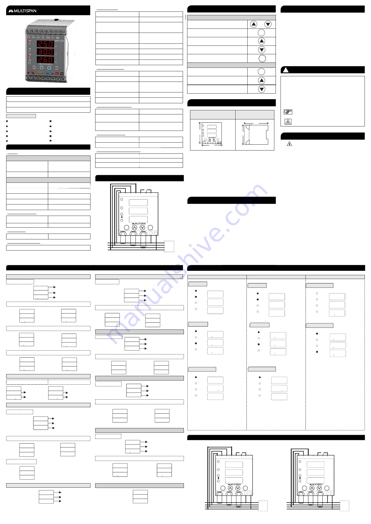
MPD-152
Motor Protection Device
Over/Under Current
Over/Under Frequency
Over/Under Voltage
Single Phase Prevention
Short Circuit
Unbalance
Phase Loss
Lock Rotor Point
Phase Sequence
User Selectable Trip Time
Auto/Manual Reset Function
True RMS Measurement
INPUT :
Voltage AC
Direct Voltage AC
30 to 300V(L - N)
50 to 520V(L - L)
Burden
Voltage AC
Current AC
Burden
Primary CT Ratio
Secondary Current AC
Overload
Frequency
Up to 6A continuous
45.0 to 65.0 Hz
DIMENSION :
Size (mm)
NETWORK SELECTION :
3 Phase - 4 Wire,
TRIP SETTING :
Under Current
0.00 to CTR
0.00 to CTR
Over Current
FEATURES
Protection Available
Under Voltage
50 to 520V For 3Ø - 3W
30 to 300V For 3Ø - 4W
Over Voltage
50 to 550V For 3Ø - 3W
30 to 330V For 3Ø - 4W
Over / Under Frequency
45.0 to 65.0 Hz
Lock Rotor Point
0.5 to 9.0 Scale
Short Circut
1 - 9 Scale
Unbalance
5 - 60%
TIME PARAMETER :
Power On Delay
0 to 99 Sec
Initial Time Delay
0 to 99 Sec
Trip Delay Time
0 to 999 Sec
(Voltage, Current, Frequency,
SSP, Unbalance)
Scrolling Time
1 to 99 Sec
Reset Time
0 to 99 Sec
OUTPUT SPECIFICATION :
Relay
1 Nos
Relay Type
Supply Voltage
100 to 270V AC, 50Hz
Power Consuption
3VA @ 230 AC MAX
Rating
10Amp, 250V AC
AUXILIARY SUPPLY :
KEY OPERATION
To View Individual Parameters Value
OR
Operator Mode
To Reset The Relay Contact manually after
Tripping
Parameter Setting Mode
TECNICAL SPECIFICATION
3 Phase - 3 Wire,
TERMINAL CONNECTION
MAINTENANCE
MECHANICAL INSTALLATION
Under Current fault Message
1) Unc in R Phase
2) Unc in Y Phase
3) Unc in B Phase
4) Unc in RY Phase
5) Unc in YB Phase
6) Unc in RB Phase
7) Unc in RYB Phase
Under Current
R phase Current Value
U N C
R
2 8 7
Fault in R phase
U N C
Y
2 7 2
U N C
B
2 6 3
U N C
R Y
2 7 0
U N C
Y B
2 6 0
U N C
R B
2 5 5
U N C
R Y B
2 5 5
Over Frequency Fault Message
Over frequency
Frequency Value
O V F
5 2 6
Unbalance Fault Message
1) Unb in R Phase
2) Unb in Y Phase
3) Unb in B Phase
4) Unb in RYB Phase
Unbalance
Unbalance Percentage
Between R & B Phase
U N B
R B
5 5
Fault Between R & B Phase
U N B
R y
5 9
U N B
Y B
5 7
U N B
R Y B
5 5
Phase Loss Message
1) R Phase loss
2) Y Phase loss
3) B Phase loss
Phase
Loss
P H A
R
L O S
P H A
Y
L O S
P H A
B
L O S
Phase Sequence Message
Phase
Fault
P H A
S E Q
F L T
Sequence
< 0.2VA
5 to 6000 Amp selectable
ENVIRONMENTAL CONDITION :
Working Temperature
Storage Temperature
Relative Humidity
0 to 55°C
0 to 55°C
95 % RH Non-Condensing
FAULT MESSAGE
To Enter In Parameter Setting Mode
To View The Voltage Page While Display
Indicate fault
To View The Current Page While Display
Indicate fault
Edited Parameter Value to be Set, And Move
to the Next Step
To Increment Parameter Value
To Decrement Parameter Value
1)
V
LN
Page
< 0.2VA
WIRING CONNECTION
1) 3 Phase - 4 Wire
2) 3 Phase - 3 Wire
Page - 1
3)
Frequency
Page
R
0.5 to 5 Amp
3
ø
- 4W NETWORK CONNECTION
1)
V
LL
Page
2) Amp Page
1) Fault Massage
2) KA Page
L1
L2
L3
V
R
I
KA
2 4 0
2 4 0
2 4 0
f R Q
5 0 0
H Z
4 2 0
4 2 0
4 2 0
r
U N C
2 8 7
1 2 0
1 2 0
1 2 0
Under Frequency Fault Message
Under frequency
Frequency Value
U N F
5 2 6
Single Phase Prevention Fault
S P P
R
1 0 0
R Phase Fault
Single Phase Prevention
R - Phase Voltage Value
2) SPP in Y Phase
S P P
Y
1 0 5
3) SPP in B Phase
S P P
B
1 1 0
R
L O S
S P P
Y
L O S
S P P
B
L O S
S P P
Lock Rotor Point
L R P
R
5 0 0
R Phase Fault
Lock Rotor Point
Phase Currunt Value
L R P
Y
5 0 0
L R P
B
5 0 0
Frequency Fault Message
SPP Fault Due to Phase Loss
Single Phase Prevention
R Phase
Loss
1) SPP in R Phase
1) SPP in R Phase
2) SPP in Y Phase
3) SPP in B Phase
1) LRP in R Phase
2) LRP in Y Phase
3) LRP in B Phase
3
ø
- 3 W NETWORK CONNECTION
3
ø
- 3W / 3 - 4W NETWORK CONNECTION
Neutral Loss
1 C/O (NO-C-NC)
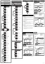
DISPLAY PAGES
SET
S1
S2
S1
S2
S1
S2
L1
L2
MPD 152
L3
L1
L2
R
V
KA
L3
N
NO
C
NC
RST
L
N
DISPLAY AND KEYS :
Display
3 Digit, 3 Line 7 Seg 0.28”,
RED LED
Keys
SET, INC, DEC, RST
L1
L2
L3
V
R
I
KA
2)
Amp
Page
5 0 0
5 0 0
5 0 0
L1
L2
L3
V
R
I
KA
L1
L2
L3
V
R
I
KA
L1
L2
L3
V
R
I
KA
5 0 0
5 0 0
5 0 0
f R Q
5 0 0
H Z
L1
L2
L3
V
R
I
KA
L1
L2
L3
V
R
I
KA
L1
L2
L3
V
R
I
KA
SET
RST
S1
S2
S1
S2
S1
S2
L
N
L1
L2
MPD 152
L3
L1
L2
V
KA
L3
N
NO C
NC
L1
L2
L3
N
TO
LOAD
R
SET
RST
S1
S2
S1
S2
S1
S2
L
N
L1
L2
MPD 152
L3
L1
L2
V
KA
L3
N
NO C
NC
L1
L2
L3
N
TO
LOAD
R
SET
RST
S1
S2
S1
S2
S1
S2
L
N
L1
L2
MPD 152
L3
L1
L2
V
KA
L3
N
NO C
NC
L1
L2
L3
N
TO
LOAD
R
Front View (mm)
Side View(mm)
1) To install the instrument on a DIN rail, raise the clamp at the
back of the instrument and place it on the rail. Now release
the clamp, so the instrument fits on the DIN rail.
2) Ensure proper fitting of the instrument by pulling it outwards.
3) To remove the instrument raise the clamp to release it from
the DIN rail.
4) The equipment in its installed state must not come in close
proximity to any heating source, caustic vapors, oil steam, or
other unwanted process byproducts.
5) Do not connect anything to unused terminals.
Read complete instructions prior to installation
and operation of the unit.
WARNING :
Risk of electric shock.
SAFETY PRECAUTION
!
All safety related codifications, symbols and instructions
that appear in this operating manual or on the equipment
must be strictly followed to ensure the safety of the operating
personnel as well as the instrument.
If all the equipment is not handled in a manner specified
by the manufacturer, it might impair the protection provided
by the equipment.
WARNING GUIDELINES
WARNING : Risk of electric shock.
1) To prevent the risk of electric shock, power supply to the
equipment must be kept OFF while doing the wiring
arrangement. Do not touch the terminals while power is
being supplied.
2) To reduce electro magnetic interference, use wire with
adequate rating and twists of the same of equal size shall
be made with shortest connection.
3. Cable used for connection to power source, must have a
cross section of 1mm or greater. These wires should have
insulations capacity made of at least 1.5kV.
4) A better anti-noise effect can be expected by using
standard power supply cable for the instrument.
1) Do not allow pieces of metal, wire clippings, or fine
metallic fillings from installation to enter the product or
else it may lead to a safety hazard that may in turn
endanger life or cause electrical shock to the operator.
2) Circuit breaker or mains switch must be installed
between power source and supply terminal to facilitate
power ‘ON’ or ‘OFF’ function. However this mains switch
or circuit breaker must be installed at convenient place
normally accessible to the operator.
INSTALLATION GUIDELINES
3) Use and store the instrument within the specified ambient
temperature and humidity ranges as mentioned in this
manual.
1) The equipment should be cleaned regularly to avoid blockage
of ventilating parts.
2) Clean the equipment with a clean soft cloth. Do not use
isopropyl alcohol or any other cleaning agent.
MAINTENANCE
3) Fusible resistor must not be replaced by operator.
SET
SET
RST
240
240
240
75(H)X 55(W)X110(D)
75
55
110
Neutral Loss Message
R
1 5 8
S P P
NOTE : Neutral loss Protection available Only,
In Case Of SPP Enable
75
MAINTENANCE
MAINTENANCE
3)
Frequency
Page


