background image

CommPlete 4000

Communications Server

User Guide

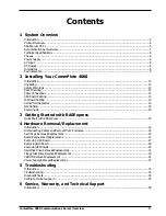
Summary of Contents for CommPlete 4000

Page 1: ...CommPlete 4000 Communications Server User Guide...

Page 2: ...blication and to make changes from time to time in the content hereof without obligation of Multi Tech Systems Inc to notify any person or organization of such revisions or changes Record of Revisions...

Page 3: ...ades 14 NIC Cabling 15 Powering Up 16 3 Getting Started with RASExpress Quick Start with RASExpress 18 4 Hardware Removal Replacement Introduction 24 Disconnecting Cables and Removal from Enclosure 24...

Page 4: ...or 42 6 Pin Circular Jack 43 RJ 45 Connector 44 34 Pin Floppy Disk Drive Connector 44 Printer Port Connector 45 COM 2 Port Connector 45 Hard Disk Connector 45 Appendix B Regulatory Information 46 FCC...

Page 5: ...CommPlete 4000 Communications Server Overview 5 1 System Overview...

Page 6: ...mPlete 4000 is shipped with factory installed RASExpress server software for remote access functionality Each CommPlete 4000 has a default configuration that allows it to boot as a RAS unit The four C...

Page 7: ...Intelligent Serial Interface Cards ISI5634PCI 8 ISI5634PCI 8 ISI5634PCI 8 CommPlete 4000 Single Processor Data Communications Server Figure 1 2 Typical RASExpress Application Additional noteworthy fe...

Page 8: ...8 ISIHP 4S orISIHP 4U Power Supply AC Input Power requirement 100 120 220 240V 6A 3A RMS selectable by slide switch Frequency 50 60 Hz Efficiency 65 full load nominal line DC Output Output 5 25A 12 10...

Page 9: ...of the backplane such PCI expansion cards will not operate properly in those positions Dimensions Height 5 25 inches Width 19 inches Depth 17 inches Weight 31 lbs 14kg Environmental Temperature 0 40o...

Page 10: ...10 CommPlete 4000 Communications Server Overview...

Page 11: ...CommPlete 4000 Communications Server Overview 11 2 Installing Your CommPlete 4000...

Page 12: ...ing telephone lines Avoid using a telephone other than a cordless type during an electrical storm There may be a remote risk of electrical shock from lightning Do not use the telephone to report a gas...

Page 13: ...may involve connection to three back panel connectors see Figure 2 2 The back panel connectors are Video connector COM 1 connector Keyboardconnector SBC Backplane 6 Pin Circular Jack To External Keyb...

Page 14: ...us Consequently if both slots are used they must be occupied with identical devices and the device drivers must be identical This is a constraint of PCI bus architecture Also the device drivers must s...

Page 15: ...ner slot NIC Cabling The 10 100Mb PCI EtherNet Network Interface Card is located as shown in Figure 2 4 The NIC has a single RJ 45 connector and three LEDs Network Interface Card 120 RJ 45 UTP Connect...

Page 16: ...16 CommPlete 4000 Communications Server Overview...

Page 17: ...CommPlete 4000 Communications Server Overview 17 3 Getting Started with RASExpress...

Page 18: ...4000 server Optional a client PC connected to the CommPlete 4000 s network and equipped with Telnet a browser or MultiManager Accessing RASExpress To configure the CommPlete 4000 as a RASExpress serv...

Page 19: ...ver A6 Enable IP Remote Access Note Error messages will appear and will indicate that the remote addresses of the WAN ports are not on the same subnet This is normal for the initial setup Ignore these...

Page 20: ...ss Enter The connection closes while the RASExpress server re boots A new menu appears after the CommPlete 4000 has re booted A17 To complete the configuration of the RASExpress server select Configur...

Page 21: ...r B6 Enable IP Remote Access Note Error messages will appear and will indicate that the remote addresses of the WAN ports are not on the same subnet This is normal for the initial setup Ignore these m...

Page 22: ...RASExpress main menu appears Using TCP IP Access Run your Telnet software and connect to the IP address of the RASExpress server The RASExpress main menu appears B11 At the Telnet main menu select Con...

Page 23: ...CommPlete 4000 Communications Server Overview 23 4 Hardware removal Replacement...

Page 24: ...label all cable connections before disconnecting any cables from the CommPlete 4000 1 Remove the power cord from the back of the CommPlete 4000 2 If connected disconnect the video COM 1 and keyboard c...

Page 25: ...led into or removed from the SBC side of the card cage without removing the card cage However installing removing an expansion card from the opposite side requires removal of the card cage see Figure...

Page 26: ...t of the chassis See Figure 4 5 Set it next to the chassis Note Before placing the card cage back into the chassis verify that the power connectors from the power supply to the backplane are fully att...

Page 27: ...e are needed Follow the procedure Disconnecting Cables and Removal from Enclosure presented above Summary after powering down the unit and disconnecting all power and signal cables employ two persons...

Page 28: ...place the SBC board verify SBC board configuration Refer to the Hardware Configuration and Installation instructions in the SBC manual 8 Install the new SBC board by following steps 1 5 in reverse ord...

Page 29: ...removing or replacing the single ISI board on the left side looking from the front of the midplane card cage removal is not necessary Ignore steps 3 through 5 1 Remove the CommPlete 4000 from rack en...

Page 30: ...nting tabs b Replace drive chassis mounting screws 3 c Reconnect power and data cables d Replace top cover 7 screws e Two people are needed Replace CommPlete 4000 into rack enclosure Floppy Disk Drive...

Page 31: ...crews securing the CDROM drive to the drive chassis 7 Open the front door and remove CDROM drive by sliding it out the front of the drive chassis 8 To install a new CDROM drive follow steps 1 7 in rev...

Page 32: ...he switch 9 Remove the three power supply mounting screws from the back of the CommPlete 4000 10 Remove the power supply from the chassis 11 To install a new power supply follow steps 1 7 in reverse o...

Page 33: ...CommPlete 4000 Communications Server Overview 33 5 Troubleshooting...

Page 34: ...e all connectors from the SBC and adapter boards except the video connector and then power ON the CommPlete 4000 If the CommPlete 4000 now has video then there is a problem with one of the cables or o...

Page 35: ...a large 5 pin DIN to a small 6 PIN PS 2 DIN check it the cable converter to see if it is defective or the wrong type Verify that the keyboard works on a different system If problem persists contact M...

Page 36: ...36 CommPlete 4000 Communications Server Overview...

Page 37: ...CommPlete 4000 Communications Server Overview 37 6 Service Warranty and Technical Support...

Page 38: ...tomer or any party without MTS s written authorization or used in any manner inconsistent with MTS s instructions MTS s entire obligation under this warranty shall be limited at MTS s option to repair...

Page 39: ...ion product upgrade data problem solving tips and a message service for you to leave questions for which you would like additional information The phone number for the Multi Tech BBS is 612 785 3702 o...

Page 40: ...prefer to receive e mail technical support via the Internet you can contact Tech Support at the following address http www multitech com _forms email_tech_support htm Multi Tech s presence includes a...

Page 41: ...CommPlete 4000 Communications Server Overview 41 Appendices...

Page 42: ...signals for VGA monitors 1 5 10 6 11 15 Figure A 1 15 Pin VGA Connector Pin Identification Pin Description 1 Analog Red 2 Analog Green 3 Analog Blue 4 VESA Monitor Status Bit 2 5 DigitalGround 6 Digit...

Page 43: ...oard 1 2 3 4 5 6 Figure A 3 6 Pin Mini DIN Keyboard Connector Pin Identification PinDescription 1 KeyboardData 2 NC 3 GND 4 5VDC 5 KeyboardClock 6 NC RJ 45 Connector This connector ties the EN Series...

Page 44: ...und 9 Ground 26 Track 0 10 Motor Enable 1 27 Ground 11 Ground 28 Write Protect 12 Drive Select 2 29 Ground 13 Ground 30 Read Data 14 Drive Select 1 31 Ground 15 Ground 32 Select Head 16 Motor Enable 2...

Page 45: ...rivers to provide the read write functions 40 1 2 39 Figure A 7 Hard Disk Connector Pin Description Pin Description 1 Reset 21 NC 2 Ground GND 22 Ground GND 3 Data Bit 7 SD7 23 I O Write IOW 4 Data Bi...

Page 46: ...ou in advance that temporary discontinuance of service may be required But if advance notice isn t practical the telephone company will notify the customer as soon as possible Also you will be advised...

Page 47: ...n rural areas Caution Users should not attempt to make such connections themselves but should contact the appropriate electric inspection authority or electrician as appropriate Compliance with BABT R...

Page 48: ...ommunication Module Carrier Card Expansion Card X X Example Diagram Showing Creepage and Clearance Distances Y Y Fig B 1 Example Diagram Showing Creepage and Clearance Distances Except at the edge con...

Page 49: ...umber The REN value of a unit is calculated from 3 n where n is the total number of units which can be connected in parallel which will still cause the standard bell as defined in BS6305 Appendix D to...

Page 50: ...re dc from the Private Circuit for correct operation The modem may be damaged if connected in a private circuit mode to a circuit supplying dc current the maximum permissible direct current is zero am...

Reviews: