MuxLab VideoEase 500090, Installation Manual
The MuxLab VideoEase 500090 is a versatile video distribution system that ensures high-quality signal transmission. To easily set up and configure this product, download the free Installation Manual from our website. This comprehensive manual provides step-by-step instructions for seamless installation, giving you the utmost convenience and control.
Share
Download


Reviews:
No comments
Related manuals for VideoEase 500090

IR Link Pro
Brand: Ebode Pages: 8
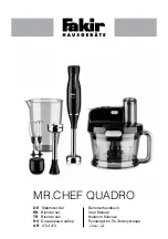
MR.CHEF QUADRO
Brand: Fakir Pages: 72

USB Rover 2850
Brand: Icron Pages: 2

USB 3.0 Spectra 3022
Brand: Icron Pages: 2

UHD-EXB350EAU-K
Brand: Orei Pages: 21

Certified Reconditioned 780
Brand: Vitamix Pages: 40

8RGRA-H01C01S0PE
Brand: Pengo Pages: 13

Dynapro DPS-1050
Brand: Tribest Pages: 60

Matrixline 2000 Series
Brand: KVM-TEC Pages: 55

MegaView 76
Brand: Marmitek Pages: 52

Mini Mixx MM1R
Brand: Euro Cuisine Pages: 52

TL-WA820RE
Brand: TP-Link Pages: 2

Space-Saving Blender
Brand: Hamilton Beach Pages: 24

DL-Vision(M/S)-AR
Brand: G&D Pages: 56

KX1000
Brand: KING Pages: 16

LM-HE150
Brand: LINK-MI Pages: 5

RP-N53
Brand: Asus Pages: 119

94114
Brand: Gordon Pages: 4


