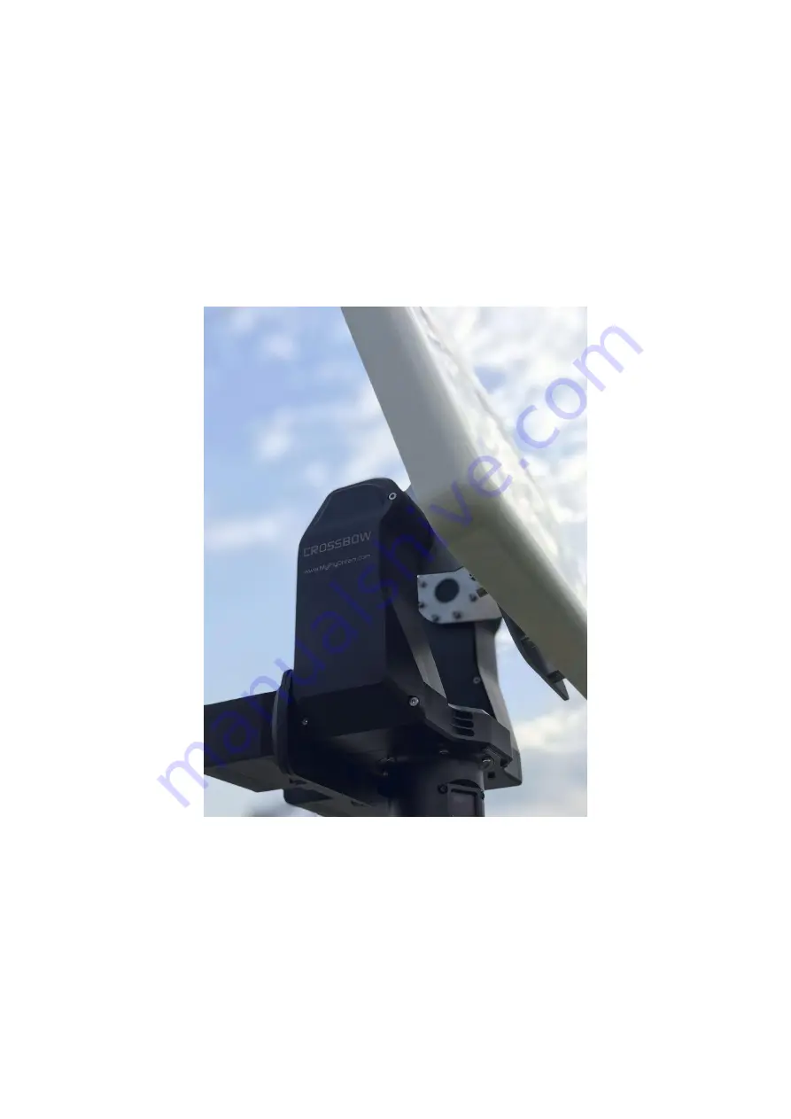
background image


Crossbow AAT 

Manual 

V 1.1 


 2019-Aug-29 


www.MyFlyDream.com


Summary of Contents for Crossbow AAT

Page 1: ...Crossbow AAT Manual V 1 1 2019 Aug 29 www MyFlyDream com ...

Page 2: ...the aircraft thus allowing the video receiver to pick up the strongest signal possible at given distance and other factors In order to obtain better signal reception quality it is advised to use high gain receiving antennas High gain antennas are known for very narrow angles of effective reception For its successful operation Crossbow AAT requires the flight data such as latitude and longitude of ...

Page 3: ...s Tracking Ability MAX Pan Speed 300deg s MAX Tilt Speed 60deg s MAX Pan Angle Unlimited 450deg MAX Tilt Angle 15deg 135deg Mechanical Electrical specifications Weight 2 6kg MAX Tilt Torque 14kgf cm Operating Voltage 12 16V DC Power Consumption 15W Typical Protocol Interface MFD VBI All MFD Autopilots TeleFlyPro TeleFlyTiny supported MAVLink MAVLink V1 0 V2 0 supported 2 Installation and wiring 1 ...

Page 4: ...nding power socket of the AAT as shown in the picture 2 The antenna has to be mounted on the Crossbow AAT with the use of a special bracket In order to prevent tampering with the normal operation of the compass built into the Crossbow AAT it is recommended to avoid using antennas made with ferromagnetic materials Wherever possible use non magnetic stainless steel bolts aluminum and other non magne...

Page 5: ...3 There is an aviation socket on the main unit the upper connector and a cable with aviation plug and color coded wires ...

Page 6: ...og video input 3 Gray External GPS RX U2 RX This pin maybe not available in later version The UART2 has been move to the top of the LEFT ARM of Crossbow 4 Orange Telemetry Data TX U3 TX connected with RX of your DataRadio 5 Blue Telemetry Data RX U3 RX connected with TX of your DataRadio 6 Black Ground If you wish to use MAVLink protocol to provide tracking data through digital radio link Fix the ...

Page 7: ...ital radio link to the green line of the cable Power on the digital radio link Usually the UAV ground station also needs to be connected to the digital radio link Sharing the TX line of the digital radio link with Crossbow AAT will not affect the normal ground station operation 4 The base of the AAT has 2 similar aviation sockets for use with 2 matching cable with a aviation plugs and color coded ...

Page 8: ... Definition PIN Wiring Color Definition 1 Orange Telemetry Data TX U3 TX connected with RX of your DataRadio 2 Blue Telemetry Data TX U3 RX connected with TX of your DataRadio 3 Red 12V 16V power supply shared AAT power supply voltage ...

Page 9: ...t Connected 2 Blue Not Connected 3 Red Not Connected 4 Gray Not Connected 5 Yellow Analog video output 6 Black Ground There is also a Crossbow RF model which uses a RF Slipring inside With this RF version users can mount their antenna on the tracker and access the signal Up to 3GHz with the lower N Connector of the Crossbow The RF model looks a little bit different ...

Page 10: ...will recognize the GPS Compass module once it s plugged The screen will display something like GPS 12 L14 to show the number of satellites locked by remote GPS local GPS With this module The tracker will start to track when it locks enough satellites without setting home operation ...

Page 11: ...r will be displayed alternatively When you get enough satellites locked usually 8 or more press the right button on the base to SetHome for the tracker With MFD AP MFD Crosshair you can SetHome for your plane meanwhile the Home location of the tracker will also be set Once the plane flies to 10 meters away the tracker will start to track Crossbow can work in 2 modes Unlimited 450degrees In Unlimit...

Page 12: ...milar will happen in the opposite way Mostly the tracker can rotate 360 45 45 450degrees That s why we call it 450degrees mode 4 Downlink The Crossbow AAT needs a downlink to get the information of the tracking plane Usually this is the most difficult part to get your system to work Because you have to merge several devices came from different manufactories We may extend this chapter in the future...

Page 13: ... video RX outputs clear videos check with an AV monitor Feed the signal to PIN 2 of the upper socket of course you need a common Ground wire between your VideoRX and the tracker Note that you need to make sure the plane side and the tracker are using the same VBI version If the tracker decodes information from the video signal successfully the main screen will display like VLink 90 2 DataRadio MAV...

Page 14: ... of the tracker to establish a downlink In this case usually you also need a HDMI cable or Ethernet cable to get video signal from the VideoRX on the tracker These cables limits the tracker to rotate continuously You need to use the tracker in 450 degrees mode Finally you have this solution The tracker pitch yaw the antenna only Your VideoRX and DataRadio stay on the ground and connect with your a...

Page 15: ...rollers In this case FlightInfo ALT BARO are both from MAVLINK_MSG_ID_GPS_RAW_INT message We recommend our users to set the update frequency of the above 2 messages higher to get better tracking performance The method varies from different Flight Controllers Take the ArduPilot Mega as an example you can search for string SR1_ in Mission Planner All parameters List to get a table of MAVLink message...

Page 16: ...AIN MENU YawTrim HomePos CalCompass MotorCurr CalPitch CompassMod BaudRate FlightInfo PayloadSel OSDLevel VBISetting Protocol TrackerID SysInfo Factory Exit YawTrim Yaw 0 Pitch 0 Exit If the tracker is slightly tracking the plane left or right you can apply some YawTrim to make it more accurate Use Negative values to trim the tracker to LEFT Use Positive values to trim the tracker to RIGHT You can...

Page 17: ...this function will be helpful especially you have a proper pre saved home position in the tracker AutoLoad N means the tracker will not load the most recent home position when it starts up Click the right button to set AutoLoad Y to enable it CalCompass CalCompass MAX 125 Exit AutoLoad N Exit Click the right button to execute a compass calibrate the compass of the tracker Before doing that please ...

Page 18: ...ave H Pos to save this High Position 5 Save Exit CompassMod UseCompass InitOnly Always Never Exit This setting is about how to use the compass of the tracker InitOnly The tracker only reads the compass to know where is North when starting up Later it will use an internal optical encoder to work smoothly without the compass In this case you can t rotate your tripod because the tracker is not able t...

Page 19: ...from the barometer of the plane PayloadSel Payload Light Midium Heavy UltraHeavy Exit Choose the payload level of your setup Light Light Weight antennas high acceleration and fast movements UltraHeavy Very Heavy antennas low acceleration and slow movements OSDLevel Brightness Level 90 Exit Choose the OSD OnScreenDisplay brightness level of the tracker The tracker is able to overlay some graphics i...

Page 20: ...t necessary information from it V2 works better in long range Protocol Protocol ALT BARO Exit Choose ALT BARO or ALT GPS to determine what altitude data of the MAVLink data stream will be used to track We will discuss this in the chapter 5 Downlink TrackerID TrackerID ID 1 Exit Choose the numeral ID of the tracker When you use FlyTogether function your ID will be displayed on other s OSD screen Yo...

Page 21: ...PitchTest AllTest CoreData Exit This screen is reserved for the manufacture ...

Page 22: ...Appendix A ...

Page 23: ......

Page 24: ...r pitch tracking Which specific ALT setting you need to use depends on the behaviour of your AutoPilot Due to the imperfect world of MAVLink you need to pay more attention about the Altitude information of MAVLink There are about 6 7 places allow the autopilots to send altitude data or barometer data It s difficult to tell which altitude is exact you need There are altitudes based on GPS ASL based...

Page 25: ...iver for USB TTL if necessary http www myflydream com inc lib download download php DId 30 download the MFD FW update tool you need Net 4 0 framework to use it http www myflydream com inc lib download download php DId 61 Choose 38400 baudrate for Crossbow You need to power on your Crossbow to update firmwares ...

Page 26: ...pear to ask you to confirm the update Click YES Just wait for a few seconds until the update finishes Please check these settings after update 1 Set Baudrate to the value that you need to work with your gears 2 Set Current of your 2 motors by menu MotorCurr Usually you can use 2000ma for both motors 3 Calibrate the compass module with menu CalCompass If you have an external GPS compass module plea...

Reviews: