background image

S82 W18717  Gemini Drive

Muskego, Wisconsin 53150

Phone:  (877) 622-2694

Fax:  (888) 679-3319

www.nabcoentrances.com

Technical Support:  (866) 622-8325

WARNING

• Turn OFF all power to the Automatic Door if a Safety System is not working.

• Instruct the Owner to keep all power turned OFF until corrective action can be achieved by a NABCO 

trained technician. Failure to follow these practices may result in serious consequences.

• NEVER leave a Door operating without all Safety detection systems operational.

Part #C-00140 

Rev. 10/7/16

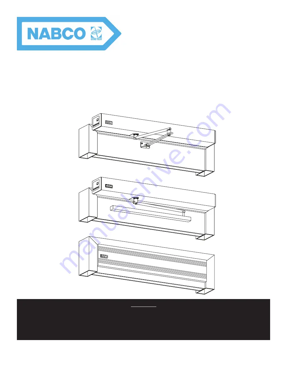
GT20 Swing Door Operator 

Wiring and Programming Manual 

**With GT20 Control**

DN 1145

Summary of Contents for GT20

Page 1: ...ty System is not working Instruct the Owner to keep all power turned OFF until corrective action can be achieved by a NABCO trained technician Failure to follow these practices may result in serious c...

Page 2: ...THIS PAGE IS INTENTIONALLY LEFT BLANK...

Page 3: ...l 5 11 Section 5c Safety with Monitoring Function 5 12 Section 5d Locking Devices 5 13 Section 5e Single Swing Door 5 14 Section 5f Double Swing Door Master 5 15 Section 5g Double Swing Door Slave 5 1...

Page 4: ...Settings 8 35 Section 8f Sensor Signals 8 35 Section 8g Emergency Stop 8 36 Section 8h Check Connections 8 36 Section 8i Interlock Operation 8 36 Section 8j Check Connections 8 37 CHAPTER 9 RELAY PRIN...

Page 5: ...the function impaired Notice Indicates a statement of company policy as the message relates to the personal safety or protection of property Notice should not be used when there is a hazardous situat...

Page 6: ...Disconnect power at the branch circuit protection during all electrical or mechanical service When uncertain whether power supply is disconnected always verify using a voltmeter All electrical troubls...

Page 7: ...SI standard Both Full Power and Low Energy Swing door Units are listed by UL according to UL325 and is identified as such on the label Instruct the building owners and operator on the essentials of th...

Page 8: ...g located near the top of inside Header Ensure that the Grounding of the Electric Power Supply is installed connected in a proper way especially the PE Cable from the Building Side Attention Depending...

Page 9: ...Figure 3 1 Table 3 1 Operating Modes Automatic X X Door Panel is opened by an Activation Device or a Knowing Act X X Door Panel is closed upon expiration of the adjustable hold open time Night Door Pa...

Page 10: ...nnected always verify using a voltmeter DN 1209 Table 4 1 Terminals 1 13 Description Description Description 1 Power Program Selector Switch 7 Reference Switch Connection 13 Joystick 2 Connection Term...

Page 11: ...t Stop 14 SE 24V 15 SE Stop 16 SE Test 17 GND X106 Jumper N A N A X107 Safety Element Reverse 18 SE 24V 19 SE Rev 20 SE Test 21 GND X108 Motor or Electric Lock 27 EL 24V 28 GND 29 EL COM 30 EL NO 31 E...

Page 12: ...Power Consump on of ALL Sensors and Powered Ac va on Devices MUST NOT Exceed 1 2 Amps Exterior Ac va on Device Interior Ac va on Device SA SL SO SM SW X110 X108 27 28 29 30 31 18 19 20 21 X107 14 15 1...

Page 13: ...K SE active Safety element gn bl ge 5V OK max min 32 gn gn PG PO PI PU CG CH CL X117 SG X111 BG BU BD 14 15 17 18 19 21 COM N C PWR PWR COM N C PWR PWR Swing Side Door Mounted Sensor Approach Side Doo...

Page 14: ...32 green green PG PO PI PU CG CH CL X117 SG X111 BG BU BD ERROR E Lock Relay red white 14 15 17 19 Powered Activation Devices OUT 1 COM OUT 1 N C PWR PWR WARNING When Any Door Mounted Sensor Input is...

Page 15: ...minals 28 GND and 32 EL Fb Jumper provided by NABCO is needed between Terminals 28 GND and 29 EL COM Power for Lock 24 VDC 800mA max FAIL SECURE LOCK POWERED BY OTHER SOURCE FAIL SAFE and MAG Locks ar...

Page 16: ...or CAN BUS External Program Selector Motor Lock or Electric Lock Optionally Feedback signal Motor Lock or Electric Lock Softswitch El Fb NO NC Safety Element Reversing Swing Door Mounted Sensor Openin...

Page 17: ...CAN BUS External Program Selector Motor Lock or Electric Lock for Master Optionally Feedback signal Motor Lock or Electric Lock Softswitch El Fb NO NC Safety Element Reversing Swing Door Mounted Sens...

Page 18: ...External Program Selector Motor Lock or Electric Lock for Master Optionally Feedback signal Motor Lock or Electric Lock Softswitch El Fb NO NC Safety Element Reversing Swing Door Mounted Sensor Openin...

Page 19: ...ensor CAN BUS External Program Selector Motor Lock or Electric Lock for Master Optionally Feedback signal Motor Lock or Electric Lock Softswitch El Fb NO NC Safety Element Reversing Swing Door Mounted...

Page 20: ...N BUS External Program Selector Motor Lock or Electric Lock for Master Optionally Feedback signal Motor Lock or Electric Lock Softswitch El Fb NO NC Safety Element Reversing Swing Door Mounted Sensor...

Page 21: ...PG PO PI PU CG CH CL X117 SG X111 BG BU BD WARNING Total Power Consumption Of All Sensors And Powered Activation Devices Must Not Exceed 1 2 Amps To Other GT20 Control sim pair astragal sequenced doo...

Page 22: ...m OK SE active Safety element gn bl ge 5V OK max min 32 gn gn PG PO PI PU CG CH CL X117 SG X111 BG BU BD 14 15 17 18 19 21 COM N C PWR PWR COM N C PWR PWR Swing Side Door Mounted Sensor Approach Side...

Page 23: ...ence Sensor if used COM N O PWR PWR PG PO 16 20 PI PU 11 12 13 COM N O PWR PWR Activation Sensor WARNING When Any Door Mounted Sensor Input is not Used A Jumper Must Be In Place At Input Terminals 15...

Page 24: ...to scroll backwards Briefly push down on the Joystick to OK selection The Value will start to blink located on the lower half of the screen If ESC is selected the current Menu Page will be displayed X...

Page 25: ...p or down The Element will stop blinking and be right side up for each circumstance Region US 3 Briefly push down on the Joystick The Value will start to blink on the lower half of the screen 4 Move t...

Page 26: ...tick to OK selection Width 48 in 16 Move the Joystick to the Right or to the Left to select between 30 inches and 63 inches 17 Briefly push down on the Joystick to OK selection Weight 200 lbs 18 Move...

Page 27: ...first and then CLOSE d If the Door Panel opens much wider than the Ao angle programmed within the GT20 Control the angle can be corrected by changing the dAxis Value If the Door Panel continues to op...

Page 28: ...Page briefly push down on the Joystick Move the Joystick to the Left until the REINIT Menu is displayed REINIT 2 Briefly push down on the Joystick Move the Joystick to the Right or Left until the Ele...

Page 29: ...he will be displayed For example If the Door Panel is programmed to stay open for 5 seconds before closing the Door Panel will fully open come to a stop and then the LCD will not only display 5 the LC...

Page 30: ...or 2 X X m means closing sequence Master X X s means closing sequence Slave X X w means Interlock 3 Active error Section 7c Menu Selection Table 7 5 Menus Menu Description PARAMETER Sets the parameter...

Page 31: ...Door Panel will press against lock to engage it FLock Full Low 2 0A OFF 7 0A Sets amount of force that is applied to the door to engage the lock at the closed position It is only active if TLock setti...

Page 32: ...able Connector Y Green X X If panic breakout latch is installed and the motor is plugged in backwards or the wrong arms are chosen during programming there is a possibility the door can burst open une...

Page 33: ...Opening OPEN Opens Door Panel CL MOT Motor Close Inverse Application OExSTp OFF OFF N A X X Used to set one of the activation Values to sequential mode X X Sequential mode is used to hold the door op...

Page 34: ...al 13 Opening Command Inside LOCKED Relay switches during the time the Door Panel is LOCKED with an electric lock Table 7 8 Double Door Menu Settings for Closing Sequence and Interlock Function Elemen...

Page 35: ...2 REINIT Menu Reverts Settings back to Factory Default Element Description FACTORY RESET All settings that were programmed into the GT Control will be reset to Factory Defaults PARAM RESET Resets Sets...

Page 36: ...r Panel to open first and then the Slave Door Panel second Section 8b Safety Element Connections Safety Elements that are connected to their respective GT20 Controls X X SER Push side door mounted Sen...

Page 37: ...catch up with and then pass the Master If this is required select a higher VO Setting Range for the Slave Door Panel 7 If an electric lock is installed on the Master select the Parameter TDelay Time D...

Page 38: ...elect the Setting Range Open 3 Go to the Slave GT20 Control Select the Parameter EMY IN Select the Setting Range Open 4 Go to the Master GT20 Control Select the following parameters X X DubleD MastA X...

Page 39: ...le yo to configure the operating modes in which the Interlock system shall be active 1 Check the LCD Display on the Master GT20 Control to see if a small black w is visible on the first level connecti...

Page 40: ...nu can display the Elements Values or the Diagnostic Menu can display the Status of the Door Panel Section 9a Install the Relay PCB Board Shut Breaker OFF Failure to do so may result in serious person...

Page 41: ...ystick Down until the Element RC 0 1 is displayed RC 0 1 CLOSED 6 Briefly push down on the Joystick The Value will start to blink on the lower half of the screen 7 Move the Joystick to the Right or to...

Page 42: ...f the GT20 Control detects an Error s PSAUTO Relay switches when the Program Selector is in Mode AUTOMATIC PSNIGHT Relay switches when the Program Selector is in Mode NIGHT PSEXIT Relay switches when...

Page 43: ...ng X X A0 A Active Error 0 Most recent Error Table 10 1 Drive Mechanism Nou Description Cause Elimination Checking Time Reaction E1 01 Encoder Channel A Lost X X Check y y Encoder Connection y y Motor...

Page 44: ...is changed X X Carry out a learn cycle Upon changing the drive unit configuration H 02 Minimum opening angle has not been achieved X X Check the locking electric lock During Teach H E11 01 Halfteach r...

Page 45: ...W Update necessary After Power Up Table 10 4 Power No Description Cause Elimination Checking Time Reaction E30 01 30 V Error 30 V too low Mains failure overload motor Check 115 VAC line Replace hardwa...

Page 46: ...rectly define the role of the Closing Sequence or the Interlock Function Permanent W E71 01 CAN connection No CAN connection X X Plug in check or replace the CAN cable X X Check if all the CAN partici...

Page 47: ...Safety Sensors are active or incorrectly cabled X X Remove the obstacle X X Check the cabling between the Safety Sensor and the control unit and eliminate any detected deficiencies X X Replace the Sa...

Page 48: ...mode The Operating Mode cannot be changed Program selection keys on the side on the side cover are not lighted The ribbon cable is not plugged in correctly or not plugged in at all Check the ribbon ca...

Page 49: ...lder There must be only one single file in the FD20G folder DN 1191 Figure 11 1 Name Convention within Heirarchy Levels Section 11b Procedure 1 Verify that the USB Stick has a folder in it named FD20G...

Page 50: ...ocket X118 11 b a LCD display on the Control Unit The display of the functions is ensured via three LEDs on the control PCB SOK Green USB Loader started OE Blue Activity in progress delete write memor...

Reviews: