background image

IP-NC32

8

-VDZ


Quick Start Guide 

Summary of Contents for IP-NC328-VDZ

Page 1: ...IP NC328 VDZ Quick Start Guide ...

Page 2: ... INTERNET ACCESS THE USE OF PRODUCT SHALL BE WHOLLY AT YOUR OWN RISKS OUR COMPANY SHALL NOT TAKE ANY RESPONSIBILITES FOR ABNORMAL OPERATION PRIVACY LEAKAGE OR OTHER DAMAGES RESULTING FROM CYBER ATTACK HACKER ATTACK VIRUS INSPECTION OR OTHER INTERNET SECURITY RISKS HOWEVER OUR COMPANY WILL PROVIDE TIMELY TECHNICAL SUPPORT IF REQUIRED SURVEILLANCE LAWS VARY BY JURISDICTION PLEASE CHECK ALL RELEVANT ...

Page 3: ...f not installed and used in accordance with the instructions may cause harmful interference to radio communications However there is no guarantee that interference will not occur in a particular installation If this equipment does cause harmful interference to radio or television reception which can be determined by turning the equipment off and on the user is encouraged to try to correct the inte...

Page 4: ...pplicable harmonized European standards listed under the EMC Directive 2014 30 EU the RoHS Directive 2011 65 EU 2012 19 EU WEEE directive Products marked with this symbol cannot be disposed of as unsorted municipal waste in the European Union For proper recycling return this product to your local supplier upon the purchase of equivalent new equipment or dispose of it at designated collection point...

Page 5: ... Safety Instruction These instructions are intended to ensure that user can use the product correctly to avoid danger or property loss The precaution measure is divided into Warnings and Cautions Warnings Serious injury or death may occur if any of the warnings are neglected Cautions Injury or equipment damage may occur if any of the cautions are neglected Warnings IP NC328 VDZ Quick Start Guide W...

Page 6: ...a fire hazard Please make sure that the plug is firmly connected to the power socket When the product is mounted on wall or ceiling the device should be firmly fixed If smoke odor or noise rise from the device turn off the power at once and unplug the power cable and then please contact the service center Cautions Make sure the power supply voltage is correct before using the camera Do not drop th...

Page 7: ...p locations and do not expose it to high electromagnetic radiation To avoid heat accumulation good ventilation is required in the operating environment Keep the camera away from liquid while in use During transport the camera should be packed in its original packing or packing of the same type Improper use or replacement of the battery may result in hazard of explosion Replace with the same or equ...

Page 8: ...7 disassemble the camera yourself We do not assume any responsibility for problems caused by unauthorized repair or maintenance IP NC328 VDZ Quick Start Guide ...

Page 9: ...er the LAN 20 3 1 Wiring 20 3 2 Activating the Camera 21 3 3 Modifying the IP Address 24 4 Accessing via Web Browser 27 5 Operating via STGO2 App 29 5 1 Enable STGO2 Service on Camera 29 5 2 STGO2 Setup 32 5 3 Adding Camera to STGO2 32 5 4 Initializing the Memory Card 34 IP NC328 VDZ Quick Start Guide 2 2 MountingPreparation 12 2 3 2 Wall Mounting 17 2 3 3 Pendant Mounting 19 ...

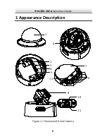
Page 10: ...9 1 Appearance Description IP NC328 VDZ Quick Start Guide 1 2 3 4 5 6 7 8 12 9 10 11 Figure 1 1 Overview of Dome Camera ...

Page 11: ...g the user name password IP address port No etc IP NC328 VDZ Quick Start Guide No Description No Description 1 Dome 7 Junction Box 2 Alarm input output 8 Sealing Plugs 3 Audio input output 9 Lens 4 Network Interface PoE 10 Reset Button 5 Power Interface 12 VDC 11 Memory Card Slot 6 Video Out BNC 12 Grounding screw ...

Page 12: ... prevent IR reflection Dust or grease on the dome cover will cause IR reflection Please do not remove the dome cover film until the installation is finished If there is dust or grease on the dome cover clean the dome cover with clean soft cloth and isopropyl alcohol Make sure that there is no reflective surface too close to the camera lens The IR light from the camera may reflect back into the len...

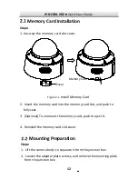
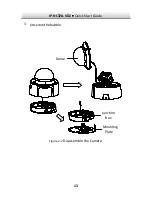
Page 13: ... Card 2 Insert the memory card into the memory card slot and push to fully seat 3 Optional To unmount the memory card push to eject it 4 Reinstall the memory card slot cover Mounting Preparation Steps 1 Lift the camera body to separate it from the junction box 2 Loosen the adapter plate screws and remove the mounting plate from the junction box ...

Page 14: ...13 IP NC328 VDZ Quick Start Guide Unscrew the bubble Dome Junction Box Mounting Plate Figure 2 2 Disassemble the Camera 3 ...

Page 15: ...he camera If routing through the ceiling cut a hole in ceiling according to the mounting and route the cables in advance If routing through the side outlet you may choose to route cables with or without conduit Steps 1 Place the mounting adapter at the desired location and mark 4 screw according to the holes marked 2 on the mounting plate 46 1 81 6 Ø4 5 0 18 Ø140 5 51 31 5 1 24 Ø45 1 77 83 5 3 29 ...

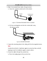
Page 16: ...nduit 2 Fit the mounting plate over the the conduit joint using Figure 2 5 Install the Conduit 3 Secure the mounting plate to the ceiling with the four supplied screws Note Use plastic anchors for installation against a cement surface and self tapping screws for installation against a wood surface 4 Route the cables through the junction box 1 Pierce the sealing plugs on the junction box the tabs a...

Page 17: ...les through the sealing plugs Note For RJ45 terminated cables use the supplied cable routing tool Cable Routing Tool Sealing Plug Figure 2 6 Route RJ45 terminated cable through Sealing Plug Junction Box Figure 2 7 Route Cables through Junction Box ...

Page 18: ...s on junction box and mountaing plate then secure the junction box to the mounting plate Safety Rope Figure 2 8 Install Junction Box 6 Hang the camera body on the safety rope 7 Connect the cables to corresponding ports on the camera Figure 2 9 Connect Cables ...

Page 19: ...nction box Figure 2 10 Affix the Camera Body 9 Adjust the viewing angle of the camera aim 1 Use supplied BNC video out cable to connect the camera to a monitor Power on the camera to obtain live image of the camera Video Out BNC To Monitor Figure 2 11 Connect Video Out ...

Page 20: ...rt Guide 2 Hold the lens to adjust the panning tilting and rotating position Pan 0 to 355 Rotate 0 to 355 Tilt 0 to 75 Figure 2 12 Adjust Viewing Angle 10 Peel off the protective films and reinstall the dome to the camera body ...

Page 21: ...te When choosing a wall mounting bracket the cap must match the mounting plate of the camera See Figure 2 3 Steps 17 1 Route the cables and install the wall mounting bracket 2 Install the cap to the bracket Secure the cap with the set screw Wall Mounting Bracket Cap Figure 2 13 Install Wall Mounting Bracket 3 Align the screw holes of the mounting plate with the corresponding screw holes of the cap...

Page 22: ...tep 4 to step 10 of Section 2 3 1 Ceiling Mounting to complete camera installation 2 3 3 Pendant Mounting The pendant mounting bracket is not included in the package Note When choosing a pendant mounting bracket the cap must match the mounting plate of the camera See Figure 2 3 Steps 1 Route the cables and install the pendant mounting bracket 2 Install the cap to the bracket Secure the cap with th...

Page 23: ...et 3 Align the screw holes of the mounting plate with the corresponding screw holes of the cap 4 Route the cables through the cable hole in the mounting plate and secure the mounting plate to the cap 5 Repeat step 4 to step 10 of Section 2 3 1 Ceiling Mounting to complete camera installation ...

Page 24: ...se strengthen your network protection If the product does not work properly contact your dealer or the nearest service center for help 3 1 Wiring Connect the camera to network according to the following figures 半球 Network Cable or Network Camera Computer Connecting Directly Figure 3 1 网络交换机 半球 Network Cable Network Cable or or Network Camera Computer Figure 3 2 Connecting via a Switch or a Router ...

Page 25: ...b browser will be shown as examples to illustrate camera activation 3 2 1 Activation via Web Browser 1 Power on the camera Connect the camera to your computer or the switch router which your computer is connected to 2 Input the IP address of the camera into the address bar of the web browser and press Enter to enter the activation interface Notes The default IP address of the camera is 192 168 1 6...

Page 26: ... and special characters in order to increase the security of your product We recommend you reset your password regularly especially in high security systems resetting the password monthly or weekly can better protect your product 4 Confirm the password 5 Click OK to save the password and enter the live view interface 3 2 2 Activation via SADP Software SADP software is used for detecting cameras on...

Page 27: ...DP software to search for cameras on the LAN 2 Select the inactive camera in the device list Select inactive camera Input and confirm password Figure 3 4 SADP Interface Note The SADP software supports batch activation 3 Create and input the new password in the password field and confirm the password IP NC328 VDZ Quick Start Guide ...

Page 28: ...nable the STGO2 service for the device during activation Refer to Chapter 5 1 for detailed information 4 Click Activate to finish activation You can check whether the activation was successful in the popup window If activation fails make sure that the password meets the minimum requirements and try again 3 3 Modifying the IP Address To view and configure the camera via LAN Local Area Network you n...

Page 29: ...elect an activated camera 3 Change the device IP address to the same subnet as your computer by either modifying the IP address manually or checking the Enable DHCP checkbox Modify the IP Address Figure 3 5 IP NC328 VDZ Quick Start Guide ...

Page 30: ... the device during activation Refer to Chapter 5 1 for detailed information 4 Input the admin password and click Modify to save IP address modification Batch IP address modification is supported by the SADPsoftware IP NC328 VDZ Quick Start Guide ...

Page 31: ...input the IP address of the camera and press the Enter key to enter the login interface Note The default IP address is 192 168 1 64 3 Input the user name and password The admin user should configure the device accounts and user operator permissions properly Delete any unnecessary accounts and user operator permissions Note The device will become locked if the admin account performs 7 failed passwo...

Page 32: ...nstall the plug in Note You may have to close the web browser to finish the installation of the plug in Download Plug in Figure 4 2 6 Reopen the web browser after the installation of the plug in and repeat steps 2 to 4 to login Note For detailed instructions of further configuration please refer to the user manual of network camera IP NC328 VDZ Quick Start Guide ...

Page 33: ...led on your camera before using the service You can enable the service through SADP software or web browser 5 1 1 Enable STGO2 Service via SADP Software Steps 1 Check the checkbox of Enable STGO2 on 1 Activate the Device page during camera activation refer to Chapter 3 2 2 2 Or Modify Network Parameters page while modifying IP address refer to Chapter 3 3 2 Create and enter a verification code Ent...

Page 34: ...red when you add the camera to the STGO2 app 3 Click and read the Terms of Service and Privacy Policy 4 Confirm and save the settings 5 1 2 Enable STGO2 Service via Web Browser Before you start You need to activate the camera before enabling the service Refer to Chapter 3 2 IP NC328 VDZ Quick Start Guide ...

Page 35: ...on com Platform Access Configuration Web Figure 5 2 3 Select Platform Access Mode as STGO2 4 Check the Enable checkbox 5 Click and read the Terms of Service and Privacy Policy in the pop up window 6 Create and enter a verification code Enter again to confirm Note The verification code is required when you add the camera to the STGO2 app 7 Confirm and save the settings IP NC328 VDZ Quick Start Guid...

Page 36: ... start You need to enable the STGO2 service on the camera before adding it to your STGO2 account Refer to Chapter 5 1 Steps 1 Use a network cable to connect the camera to a router Figure 5 3 Connect a Router Note After the camera connects to the network please wait one minute before any operation on the camera using the STGO2 app 2 In the STGO2 app tap on the upper right corner and then scan the Q...

Page 37: ...cation code of your camera Note The required verification code is the code you create or change when enabling STGO2 service on the camera If you forget the verification code you can check the current verification code on the Platform Access configuration page via a web browser 4 Follow the prompts to set the connection and add the camera to your STGO2 account Note For detailed information refer to...

Page 38: ... Storage Status in the Device Settings interface If the memory card status displays as Uninitialized click to initialize it The status will then change to Normal You can then start recording any event triggered video in the camera such as motion detection IP NC328 VDZ Quick Start Guide ...

Reviews: