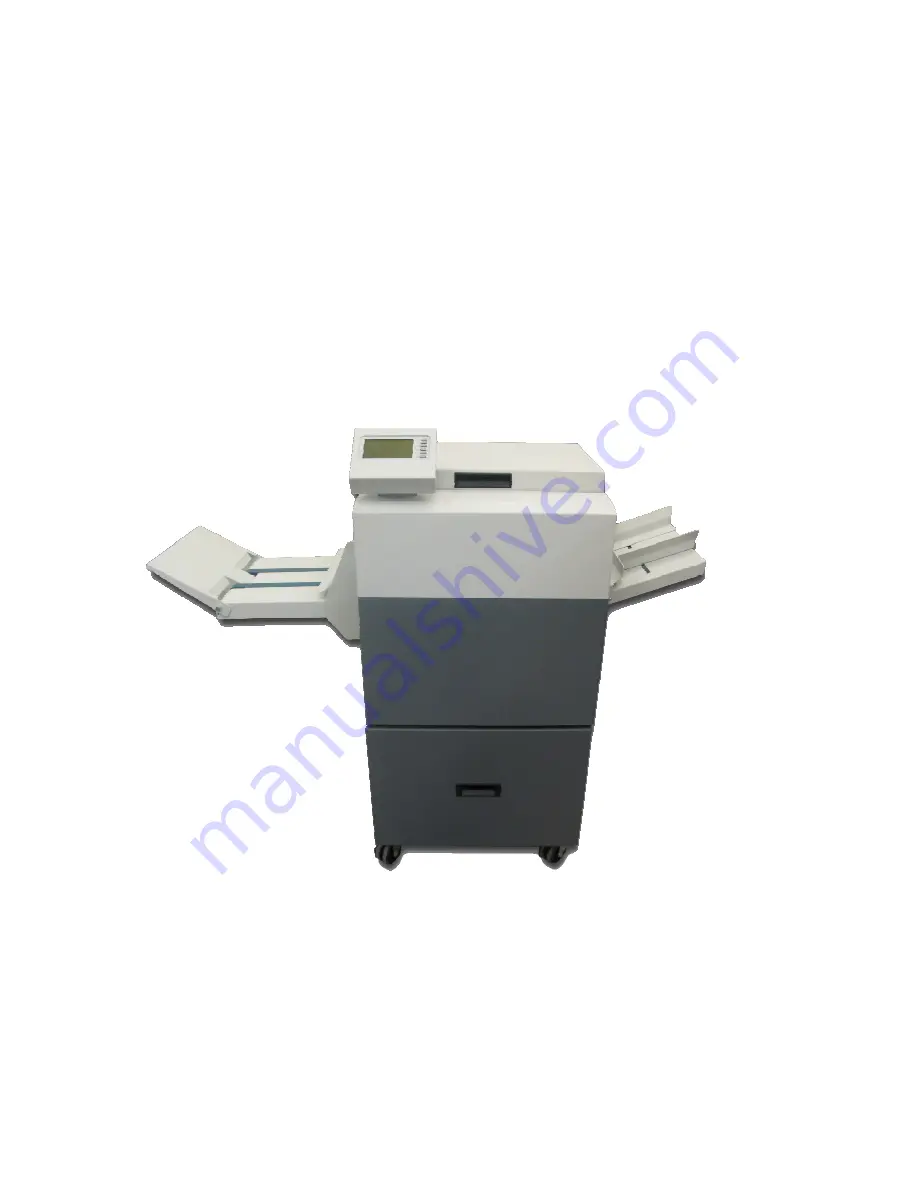
background image


2S Trimmer 

Service Manual


        Nagel 2S Trimmer 

Summary of Contents for 2S Trimmer

Page 1: ...2S Trimmer Service Manual Nagel 2S Trimmer ...

Page 2: ... Ernst Nagel GmbH 2S Trimmer Service Manual en doc Rev 1 0 20 07 2011 2 PAGE INTENTIONALLY BLANK ...

Page 3: ...3 2 TRIMMING MODE 24 4 COVERS 29 4 1 FRONT COVER 29 4 2 REAR COVER 30 4 3 UPPER INFEED COVER 31 4 4 LOWER INFEED COVER 32 4 5 UPPER OUTFEED COVER 33 4 6 LOWER OUTFEED COVER 34 4 7 BASE PLATE COVER 35 4 8 USER INTERFACE COVER 36 5 TROUBLESHOOTING 37 5 1 SERVICE PROGRAM MODE 37 5 1 1 Software Version 38 5 1 2 Diagnostics 39 5 1 3 Motors 40 5 1 4 Solenoids 41 5 1 5 Sensors and Switches 42 5 1 6 Voltm...

Page 4: ...AND BLOWN FUSE CONDITIONS 116 6 9 ADJUSTING THICKNESS DETECTION 118 7 PCB S 119 7 1 SOFTWARE DOWNLOAD 119 7 1 1 PCB1 MD6DC 119 7 1 2 PCB5 MD6DC 120 7 1 3 PCB6 CPU 121 7 1 4 PCB8 122 7 2 LED S TEST POINTS 123 7 2 1 Motor Drive MD6DC PCB1 PCB5 123 7 2 2 CPU PCB6 PCB7 124 7 2 3 Softstart PCB4 124 7 2 4 Interlock PCB3 125 8 NVM VALUES 125 8 1 CURRENT NVM VALUES 126 8 2 ADJUSTING NVM VALUES 127 8 2 1 N...

Page 5: ...th a strong magnetic field away from the machine Never attempt to perform maintenance or repairs other than described in this manual Never remove covers or guards that are fastened with screws Never install the equipment near a radiator or any other heat source Never override or bypass electrical or mechanical interlock devices In case of unusual sounds or noises abnormal surface temperature or od...

Page 6: ...ming the bleed off booklet Booklets with a maximum up to 25 sheets 80g m2 100 pages can be trimmed from 2mm to 35mm on each short edge of the booklet to a minimum of 200mm and a maximum of 320mm finished size Thereby it is also possible to trim asymmetrical All actions concerning operating the STR and adjusting the trim settings can easily be done by using the User Interface UI on STR For example ...

Page 7: ... activities At the Rear cover there is a label which refers to the Type of machine and serial Nr Fig 1 1 1 2 Fig 1 1 Fig 1 2 To find out if it is a TAG0 TAG1 or a TAG2 etc Machine find the Yellow Square label Fig 2 2 2 3 The number that is marked on this label Fig 2 4 indicates the type TAG of the machine If nothing is marked the type of machine is a TAG0 Use only the appropriate settings procedur...

Page 8: ...res of the STR in this document can be different than the actual machine See the picture below to get familiar with the components of the STR Fig 2 5 All direction are seen from the paper flow direction No Action 1 Top Cover 2 Booklet Infeed 3 Trim Waste Bin 4 Power switch inside 5 User Interface UI 6 Booklet Outfeed Rear Front Left Right Top Bottom 1 3 2 4 Fig 2 5 5 6 ...

Page 9: ... the STR continued 2 2 2 Components overview Inside Fig 2 7 Infeed Outfeed Motor6 J5 P5 S2 PCB6 FC1 FC3 J9 P9 J Motor3 J7 P7 Motor4 Motor3 S12 J4 P4 S1 J3 P3 Front view PCB print board J Motorx Motor conn Position Sx Switch position Jx Px Connector position FCx Sensor position Motorx Motor position PCB5 J Motor4 S7 S8 S9 ...

Page 10: ...nfeed J2 P2 J1 P1 PCB2 FC3 PCB3 J Motor2 FC1 J Motor1 J6 P6 Motor2 Motor1 S10 PCB1 TR1 Trafo1 Motor5 TR13 PCB4 C1 FC7 K1 K2 DB1 J9 P9 J4 P4 PCB8 PCB7 PCBx Printboard position J Motorx Motor conn Position TRx Terminal Rail Jx Px Connector position FCx Sensor position DBx Rectifier position Sx Switch position Motorx Motor position Cx Capacitor postion Trafox Transformer position Kx Relais position F...

Page 11: ... P6 S3 S4 FC2 FC1 Motor7 S13 J10 S1 J3 P3 M1 Fig 2 9 1 2 3 Top view J Motorx Motor conn Position PCBx Printboard position 1 Docking Bracket Jx Px Connector position Kx Relais position 2 Trimmer Paper Stop Sx Switch position Cx Capacitor position 3 Transport Belts Motorx Motor position S100 Power switch position U1 Netfilter connector CNT1 Counter position U2 Power Outlet connector M1 Solenoid posi...

Page 12: ... STR continued 2 2 2 Components overview Inside continued Fig 2 10 Infeed Outfeed J7 P7 S13 Motor8 Motor4 J Motor4 Motor3 J Motor3 S12 S10 Motor1 S11 J Motor2 J6 P6 Motor2 Motor7 J Motor1 Side Side Knife Knife Knife Blocks Top view J Motorx Motor conn Position Sx Switch position Motorx Motor position Jx Px Connector position ...

Page 13: ...itch Fig 2 14 for running the system with open top covers only when an override is really needed Use the Safety block for knife beam Fig 2 15 to support the Upper Knife Beam for protection in case of adjusting or replacing Knives Use Chapter 4 1 Front Cover or 4 2 Rear cover to remove the cover Caution Overriding the Interlock circuit is dangerous This should only be done by a trained Service Engi...

Page 14: ...d 2 2 4 Components overview I CAN plug Mode Selection plug Attention Make sure the I CAN Termination plug 6P3 Fig 2 16 2 17 is present Otherwise communication problems can arise Fig 2 16 Fig 2 17 Attention Make sure the Mode Selection plug 6P13 Fig 2 18 2 19 is present Otherwise communication problems can arise Fig 2 18 Fig 2 19 6P3 6P13 ...

Page 15: ...s Infeed Outfeed Rollers No Description Article code A Conveyor Roller 2 Cpl A OGMO 0000 0272 0000 B Conveyor Roller 2 Cpl A OGMO 0000 0272 0000 C Conveyor Roller 1 Cpl OGMO 0000 0052 0000 D Thickness Measurement System OGMO 0000 0737 0000 Belts No Description Article code 1 3X Belt Flat UU20U 1521 6 x30mm OMRE 0000 0055 0000 D C B A Infeed Outfeed 1 3x Fig 2 20 ...

Page 16: ...rs No Description Article code E Conveyor Roller 2 Cpl A OGMO 0000 0272 0000 F Conveyor Roller 4 L 40mm OGMO 0000 0274 0000 G Conveyor Roller 3 Cpl B OGMO 0000 0273 0000 H Conveyor Roller 1 Cpl OGMO 0000 0052 0000 Belts No Description Article code 1 1X Belt Flat UU20U 1158 6 x30mm OMRE 0000 0054 0000 2 1X Belt Flat UU20U 1002 8 x30mm OMRE 0000 0056 0000 G F E Infeed Outfeed H 2 1 F F Fig 2 21 ...

Page 17: ... 2011 17 Contents 2 General continued 2 2 Getting to know the STR continued 2 2 5 Rollers and Belts continued Control Board Belts No Description Article code 1 1X Tooth Belt T5 107510 L 1075 OMRT 0000 0002 0000 2 1X Tooth Belt T5 42010 L 420 OMRT 0000 0003 0000 1 2 ...

Page 18: ... Purpose X Can High Low Bidirectional bus between machines in the system Carries all communication between the modules in the system Exit H L Exit Out High Low From STR next machine there called Start H L Used during system start up to assign node numbers for the Can bus INPUT It is possible that the STR is connected to a previous machine with a 15Sub D cable Through this cable the STR communicate...

Page 19: ...er aligns the booklet and transport it to the outfeed Go to Bypass mode by continue chapter 3 1 Bypass mode The Trimming mode transports the booklet from the infeed inside the 2 Side Trimmer aligns the booklet trimmes the top and bottom side of booklet and transport it to the outfeed Go to Trimming mode by continue chapter 3 2 Trimming mode On the following pages both operating modes are explained...

Page 20: ...r STR107 Empty the Trim Waste Bin When the booklet arrives inside the STR it will be transported to the output side up to the Paper stop II The infeed sensor FC3 is active The time between the start signal and sensor FC3 activation should be less than 1 second after that the STR will give an error STR101 To check if the booklet has arrived in the STR correctly III The infeed sensor FC3 is inactive...

Page 21: ...me between sensor FC3 and FC2 should be less than 3 seconds after that the STR will give an error STR103 To check if the booklet has arrived at the Paper stop correctly V The Side Joggers start to move Motor7 and Motor8 and deactivates Switch S11 and Switch S13 The Side Joggers aligning the booklet VI When the Side Joggers are reaching the absolute position adjusted Side Trim size the Side Joggers...

Page 22: ...continued VII Both Side Joggers return to their home position VIII When S11 and S13 are activated Motor7 and Motor8 stops IX The solenoid M1 will be activated and the Paper stop is going down The belt propulsion motor Motor5 starts The booklet is transported to the output side of the STR Motor5 3 Motor7 3 Motor8 3 S11 S13 Motor7 3 Motor8 3 M1 ...

Page 23: ...r stop is closing XI Outfeed Sensor FC1 is active The time between sensor FC2 and FC1 should be less than 1 second after that the STR will give an error STR105 To check if the booklet has arrived at the outfeed correctly XII Sensor FC1 is inactive The time when FC1 is activated should be less than 2 seconds after that the STR will give an error STR106 To check if the booklet was transported out of...

Page 24: ...klet arrives inside the STR it will be transported to the output side up to the Paper stop II The infeed sensor FC3 is active The time between the start signal and sensor FC3 activation should be less than 1 second after that the STR will give an error STR101 To check if the booklet has arrived in the STR correctly III The infeed sensor FC3 is inactive Sensor FC3 activation should be less than 1 s...

Page 25: ...2 should be less than 3 seconds after that the STR will give an error STR103 To check if the booklet has arrived at the Paper stop correctly When booklet is to thick it will aboard the trimming mode V The Side Joggers start to move Motor7 and Motor8 and deactivates Switch S11 and Switch S13 The Side Joggers aligning the booklet VI When the Side Joggers are reaching the absolute position adjusted S...

Page 26: ...When S11 and S13 are activated Motor7 and Motor8 stop IX The knife motors Motor 1 2 3 and 4 will be activated the booklet is trimmed to the desired Finished Size Knife home switch S10 and S12 are deactivated The counter CNT1 adds 1 Trim cycle to the total 3 Global functionality description continued Contents CNT 0001 Motor3 3 3 Motor4 3 3 FC4 Motor7 3 Motor8 3 S11 S13 Motor7 3 Motor8 3 S10 S12 FC7...

Page 27: ...s down in the Trim waste bin Sensor Waste drawer full FC4 or FC7 activation should be less than 5 seconds for more than 10 booklets after that the STR will give an error STR107 Empty the Trim Waste Bin XI When the knife home switches S10 and S12 are activated the knife motors will be deactivated XII Solenoid M1 will be activated and the Paper stop is going down The belt propulsion motor Motor5 sta...

Page 28: ...M1 is deactivated and the Paper stop is closing XIV Outfeed Sensor FC1 is active The time between sensor FC2 and FC1 should be less than 1 second after that the STR will give an error STR105 To check if the booklet has arrived at the outfeed correctly XV Sensor FC1 is inactive The time when FC1 is activated should be less than 2 seconds after that the STR will give an error STR106 To check if the ...

Page 29: ...s 1 Open the Top cover See Fig 4 1 2 Switch off the main power switch and disconnect the power cord 3 Remove Screw A See Fig 4 2 4 Lift the Front cover upwards to unhook the cover at the lower end See Fig 4 3 4 4 5 Disconnect the Ground wire 6 Remove the Front cover Installation No Action Remarks 1 For installation follow the Removal procedure in reversed order A ...

Page 30: ...Open the Top cover See Fig 4 5 2 Switch off the main power switch and disconnect the power cord 3 Remove Screw A See Fig 4 6 4 Close the Top cover 5 Lift Rear cover upwards to unhook the cover at the lower end See Fig 4 7 4 8 6 Disconnect the Ground wire 7 Remove the Rear cover Installation No Action Remarks 1 For installation follow the Removal procedure in reversed order A ...

Page 31: ...al No Action Remarks 1 Remove the Front Rear Cover See Chap 4 1 4 2 2 Switch off the main power switch and disconnect the power cord 3 Remove Screws A B on both sides of the STR See Fig 4 10 4 11 4 Remove the Upper Infeed cover from the machine See Fig 4 9 Installation No Action Remarks 1 For installation follow the Removal procedure in reversed order B A ...

Page 32: ...al No Action Remarks 1 Remove the Front Rear Cover See Chap 4 1 4 2 2 Switch off the main power switch and disconnect the power cord 3 Remove Screws C D on both sides of the STR See Fig 4 13 4 14 4 Remove the Lower Infeed cover from the machine See Fig 4 12 Installation No Action Remarks 1 For installation follow the Removal procedure in reversed order D C ...

Page 33: ...al No Action Remarks 1 Remove the Front Rear Cover See Chap 4 1 4 2 2 Switch off the main power switch and disconnect the power cord 3 Remove Screws E F on both sides of the STR See Fig 4 16 4 17 4 Remove the Upper Outfeed cover from the machine See Fig 4 15 Installation No Action Remarks 1 For installation follow the Removal procedure in reversed order E F ...

Page 34: ...al No Action Remarks 1 Remove the Front Rear Cover See Chap 4 1 4 2 2 Switch off the main power switch and disconnect the power cord 3 Remove Screws G H on both sides of the STR See Fig 4 19 4 20 4 Remove the Lower Outfeed cover from the machine See Fig 4 18 Installation No Action Remarks 1 For installation follow the Removal procedure in reversed order G H ...

Page 35: ... Fig 4 21 Fig 4 22 Removal No Action Remarks 1 Switch off the main power switch and disconnect the power cord 2 Remove Screws J K on the back of Base STR See Fig 4 21 3 Remove Base Plate cover from the machine See Fig 4 22 Installation No Action Remarks 1 For installation follow the Removal procedure in reversed order J K ...

Page 36: ...4 23 Fig 4 24 Removal No Action Remarks 1 Switch off the main power switch and disconnect the power cord 2 Remove Screws L M on the back of the User Interface See Fig 4 23 3 Remove User Interface cover from the machine See Fig 4 24 Installation No Action Remarks 1 For installation follow the Removal procedure in reversed order L M ...

Page 37: ...4 1 No Action 1 Press the Admin button Note Insert the Interlock cheater otherwise some functions do not work 2 Use the buttons to select Service and press the Enter button 3 Enter the standard access code 1974 or 1983 by using the and buttons and press the Enter button 4 Use the buttons to select the Target that need to be checked and press the Enter button 5 Press the button to exit the Service ...

Page 38: ...de continued 5 1 1 Software Version Fig 5 5 Fig 5 6 No Action 1 Enter the Service Program mode see Chapter 5 1 2 Use the buttons to select Software version and press the Enter button 3 Check the Software version of the CPU PCB6 MD6DC PCB1 and MD6DC PCB5 4 Press the button to exit the Service Program mode and enter the Operator mode ...

Page 39: ...ch All messages regardless of nature are always connected with a fault code The main self diagnostic mode Diagnostics checks the voltages the sensors solenoids and the motors If a fault is found it will be displayed as a fault code This manual lists all fault codes To correct the fault go to chapter 5 2 Fault Code Descriptions NOTE It is normal to receive the code Fault Code 00034 STR034 if no Sta...

Page 40: ... than 1 time Fig 5 10 Fig 5 11 Fig 5 12 Fig 5 13 No Action 1 Enter the Service Program mode see Chapter 5 1 2 Use the buttons to select Motors and press the Enter button Fig 5 10 3 Use the buttons to select the Motor that need to be checked and press the Enter button Fig 5 11 4 For Knife motors only press the Unlock button to change the status of the Motor Fig 5 12 5 Press the CW CCW Cycle 1 butto...

Page 41: ...the Service Program mode see Chapter 5 1 2 Use the buttons to select Solenoids and press the Enter button 3 Use the buttons to select the Solenoid that need to be checked and press the Enter button 4 Press the ON OFF buttons to check the functionality of the selected Solenoid 5 After checking press the OFF buttons to change the Status of the Solenoid back in the normal situation 6 Press the button...

Page 42: ...Which state corresponding to blocked unblocked is depending on whether the sensor or switch has inverted function or not For status definition see Service Program Mode Tables 5 1 2 No Action 1 Enter the Service Program mode see Chapter 5 1 2 Use the buttons to select Sensors and press the Enter button 3 Use the buttons to select the Sensor or Switch that need to be checked and press the Enter butt...

Page 43: ...on to exit the Service Program mode and enter the Operator mode Voltage at Analogue Value Unregulated In 23 43V Unregulated 36V before interlock PCB3 from Power supply in STR measured on Interlock PCB3 Unregulated Out 23 43V Unregulated 36V after interlock PCB3 before K1 measured on Interlock PCB3 24V 16 30V Regulated 24V distributed from interlock PCB measured on Interlock PCB3 Unregulated PCB1 2...

Page 44: ...ss reflects timing calibration counter or function in the system Fig 5 24 Fig 25 Fig 5 26 No Action 1 Enter the Service Program mode see Chapter 5 1 2 Use the buttons to select NVM and press the Enter button 3 Use the buttons to select the NVM setting that need to be checked or changed and press the or Change button 4 Use the buttons to set a NewValue Dec and press the OK button 5 Press the ESC or...

Page 45: ...e are run such as motors and solenoids The program is basically made for factory testing but can be of some use when trouble shooting Fig 5 27 Fig 5 28 No Action 1 Enter the Service Program mode see Chapter 5 1 2 Use the buttons to select Dead cycle and press the Enter button 3 Use the Start button to select the start the Dead cycle and the Stop button to end the Dead cycle 4 Press the ESC or butt...

Page 46: ...ce Manual en doc Rev 1 0 20 07 2011 46 Contents 5 Troubleshooting continued 5 1 Service program mode continued 5 1 9 Calibration Can be used for adjusting the Side Jogger correction See chapter 8 2 2 NVM Side Jogger correction Fig 5 29 ...

Page 47: ...e Timeout 55 STR 014 STR M5 Motor5 Cycle Timeout 55 STR 015 STR M5 Motor5 Short Circuit 55 STR 016 STR M5 Motor5 Open Circuit 56 STR 017 STR M6 Motor6 Pulse Timeout 56 STR 018 STR M6 Motor6 Cycle Timeout 56 STR 019 STR M6 Motor6 Short Circuit 57 STR 020 STR M6 Motor6 Open Circuit 57 STR 021 STR M7 Motor7 Pulse Timeout 58 STR 022 STR M7 Motor7 Cycle Timeout 58 STR 023 STR M7 Motor7 Short Circuit 59...

Page 48: ... S9 Faulty 72 STR 066 STR S10 S10 Faulty 73 STR 067 STR S11 S11 Faulty 73 STR 068 STR S12 S12 Faulty 73 STR 069 STR S13 S13 Faulty 74 STR 070 STR S19 S19 Faulty 74 STR 071 STR S18 S18 Faulty 74 STR 080 36V INPUT 36V input Low 75 STR 081 36V INPUT 36V input High 76 STR 082 36V OUTPUT 36V output Low 76 STR 083 36V OUTPUT 36V output High 76 STR 084 24V OUTPUT 24V Low 76 STR 085 24V OUTPUT 24V High 76...

Page 49: ... short Circuit Y N Disconnect plug 1P3 from PCB1 Check wires for Short Circuit across leads Red2 Black3 Is there a Short Circuit Y N Replace PCB1 Replace wire harness Replace wire harness Replace motor STR M1 STR 003 Motor1 Open Circuit Procedure Disconnect the motor plug M1 Enter service mode unlock and start the Motor M1 Measure between the Red and Black wire The voltage is approximately 12VDC Y...

Page 50: ... 2 when not activated Y N Go to STR 066 S10 Faulty Disconnect Motor2 STR M2 enter the Service mode and select Motor1 STR M1 in motors unlock and start Motor1 STR M1 The motor energizes Y N Go to STR 003 Motor 1 Open Circuit Connect Motor2 STR M2 Disconnect Motor1 STR M1 enter the Service mode and select Motor2 STR M2 in motors unlock and start Motor2 STR M2 The motor energizes Y N Go to STR 006 Mo...

Page 51: ...it across leads Red2 Black9 Is there a short Circuit Y N Disconnect plug 1P3 from PCB1 Check wires for Short Circuit across leads Red6 Black7 Is there a Short Circuit Y N Disconnect connector J8 Check wires for Short Circuit across leads Orange3 Violet6 Is there a Short Circuit Y N Disconnect connector J9 Check wires for Short Circuit across leads Orange3 Violet6 Is there a Short Circuit Y N Check...

Page 52: ...ect plug 1P3 from PCB1 and cycle Motor M2 Measure between points 6 and 7 The voltage is approximately 22VDC Y N Replace PCB1 Replace wire harness Replace wire harness Replace Motor M2 STR 007 Motor3 Cycle Timeout See STR 010 Motor4 Cycle Timeout STR 008 Motor3 Short Circuit Procedure Disconnect the Motor plug M3 Run the diagnostics Fault code STR 009 Open Circuit is displayed Y N Disconnect connec...

Page 53: ... approximately 12VDC Y N Replace PCB5 Replace wire harness Replace wire harness Replace Motor M3 STR 010 Motor4 Cycle Timeout Procedure Enter the Service mode and select Trimmer Knife home position STR S12 in Switches The switch indicates 1 when activated and 2 when not activated Y N Go to STR 068 S10 Faulty Disconnect Motor4 STR M4 enter the Service mode and select Motor3 STR M3 in motors unlock ...

Page 54: ...rcuit across leads Red6 Black7 Is there a Short Circuit Y N Replace PCB5 Replace wire harness Replace wire harness Replace motor STR M4 STR 012 Motor4 Open Circuit Procedure Disconnect the motor plug M4 Enter service mode and cycle the Motor M4 Measure between the Red and Black wire The voltage is approximately 22VDC Y N Disconnect connector J7 and cycle Motor M3 Measure between the Red and Black ...

Page 55: ...ect the sensor plug to Motor5 STR Motor5 Measure between the two wires for the sensor 5V and Signal ground The voltage is approximately 5VDC Y N Check wires for damage Are the wires damaged Y N Go to STR 015 Motor Short Circuit Replace wire Harness Replace Sensor Enter service mode and start Motor5 The motor starts Y N Go to STR 016 Motor 5 Open Circuit Check for obstructions Disconnect the wires ...

Page 56: ...ire harness Replace Motor M5 STR 017 Motor6 Pulse Timeout Procedure STR 018 Motor6 Cycle Timeout Go to STR 020 Motor6 Open Circuit Enter the Service mode and select Motor6 encoder in sensors Slowly rotate the motor by hand and check the value on the display Value toggles between 0 and 1 Y N Disconnect the sensor plug to Motor6 STR Motor6 Measure between the two wires for the sensor 5V and Signal g...

Page 57: ...nnect plug 5P2 from PCB5 Check wires for Short Circuit across leads Orange4 Violet 11 Is there a Short Circuit Y N Replace PCB5 Replace wire harness Replace wire harness Replace motor STR M6 STR 020 Motor6 Open Circuit Procedure Disconnect the motor plug M6 Enter service mode and cycle the Motor M6 Measure between the Orange and Violet wire The voltage is approximately 22VDC Y N Disconnect connect...

Page 58: ...the two wires for the sensor 5V and Signal ground The voltage is approximately 5VDC Y N Check wires for damage Are the wires damaged Y N Go to STR 023 Motor 7 Short Circuit Replace wire Harness Replace Sensor Enter the Service mode and select Motor7 encoder B in sensors Slowly rotate the motor by hand and check the value on the display Value toggles between 0 and 1 Y N Disconnect the sensor plug t...

Page 59: ...across leads Orange2 Violet9 Is there a Short Circuit Y N Replace PCB1 Replace wire harness Replace wire harness Replace motor STR M7 STR 024 Motor7 Open Circuit Procedure Disconnect the motor plug M7 Enter service mode and cycle the Motor M7 Measure between the Orange and Violet wire The voltage is approximately 22VDC Y N Disconnect connector J6 and cycle Motor M7 Measure between the Orange and V...

Page 60: ...the two wires for the sensor 5V and Signal ground The voltage is approximately 5VDC Y N Check wires for damage Are the wires damaged Y N Go to STR 027 Motor 8 Short Circuit Replace wire Harness Replace Sensor Enter the Service mode and select Motor8 encoder B in sensors Slowly rotate the motor by hand and check the value on the display Value toggles between 0 and 1 Y N Disconnect the sensor plug t...

Page 61: ...across leads Orange2 Violet9 Is there a Short Circuit Y N Replace PCB5 Replace wire harness Replace wire harness Replace motor STR M8 STR 028 Motor8 Open Circuit Procedure Disconnect the motor plug M8 Enter service mode and cycle the Motor M7 Measure between the Orange and Violet wire The voltage is approximately 22VDC Y N Disconnect connector J6 and cycle Motor M7 Measure between the Orange and V...

Page 62: ...sure between the Orange and Violet wire Orange2 Violet4 The voltage is approximately 24VDC Y N Disconnect plug J1 and activate Magnet1 Measure between the orange and the violet wire Orange6 Violet12 The voltage is approximately 24VDC Y N Disconnect connector 3p4 and 1p2 activate Magnet1 Measure between point 2 on 3p4 and point 12 on 1p2 The voltage is approximately 24VDC Y N Replace PCB1 reconnect...

Page 63: ...Orange1 Is there a short Circuit Y N Replace PCB1 Run the diagnostics again Fault code STR 029 Open Circuit is displayed Y N Replace PCB3 Reconnect all wires Replace wire harness Replace wire harness Replace wire harness Replace motor STR M6 STR 032 Stacker Motor1 Open Circuit Procedure Check if the Belt stacker is connected Belt stacker is connected Y N Connect Belt Stacker Disconnect Belt Stacke...

Page 64: ...leads Orange5 Violet 11 Is there a short Circuit Y N Disconnect plug 1P2 from PCB1 Check wires for Short Circuit across leads Orange3 Violet10 Is there a Short Circuit Y N Replace PCB1 Replace wire harness Replace wire harness Replace Stacker Motor STR 041 Jogger1 Not Home Procedure Check Jogger1 switch S11 Is the switch activated Y N Check if Side Jogger isn t damaged or loosened Side Jogger is o...

Page 65: ...es of Side Jogger Check if S13 is activated using the service menu S13 is activated Y N Replace wire harness Retest procedure STR 043 Motor6 home to high Procedure Check Switch S1 Is the switch activated Y N Check if S1 isn t damaged or loosened Switch is ok Y N Replace or adjust Switch S1 See Chap 6 3 4 Correct NVM values of S1 lower than 2000 Y N Adjust S1 and calibrate See Chap 6 3 4 Check for ...

Page 66: ...B1 Check dipswitches on PCB1 Dipswitches are set to 0000 Y N Set dipswitches to 0000 and restart procedure Check dipswitches on PCB5 Dipswitches are set to 1001 Y N Set dipswitches to 1001 and restart procedure Check endresistors on PCB1 1P4 and PCB6 6P3 The endresistors appear to be undamaged Y N Replace damaged endresistors Check wiring between PCB1 and PCB5 Are there any loose or broken wires Y...

Page 67: ...B5 Check dipswitches on PCB5 Dipswitches are set to 1001 Y N Set dipswitches to 1001 and restart procedure Check dipswitches on PCB1 Dipswitches are set to 0000 Y N Set dipswitches to 0000 and restart procedure Check endresistors on PCB1 1P4 and PCB6 6P3 The endresistors appear to be undamaged Y N Replace damaged endresistors Check wiring between PCB1 and PCB5 Are there any loose or broken wires Y...

Page 68: ... 9 The voltage is approximately 5VDC Y N Replace PCB1 1 Replace wire harness 2 Replace PCB2 Adjust or replace sensor FC1 STR FC1 Check for obstructions and retest procedure STR 052 FC2 Faulty Fault code STR 052 indicates that Sensor FC2 STR FC2 is faulty Procedure Enter service mode and select FC2 STR FC2 in sensors Value toggles between 0 and 1 when activated deactivated Y N Disconnect the connec...

Page 69: ...y 5VDC Y N Replace PCB1 1 Replace wire harness 2 Replace PCB2 Adjust or replace sensor FC3 STR FC3 Check for obstructions and retest procedure STR 054 FC4 or FC7 Faulty Fault code STR 054 indicates that Sensor FC4 or FC7 STR FC4 or FC7 is faulty Procedure Enter service mode and select FC4 or FC7 STR FC4 or FC7 in sensors Value toggles between 0 and 1 when activated deactivated Y N Disconnect the c...

Page 70: ...5 Motor8 Pulse Timeout STR 059 FC6 Faulty Fault code STR 059 indicates that Sensor FC6 STR FC6 is faulty Procedure Enter service mode and select FC6 STR FC6 in sensors Value toggles between 0 and 1 when activated deactivated Y N Disconnect the connector to sensor FC6 Measure between the wires to sensor FC6 5V and Ground The voltage is approximately 5VDC Y N Check wires for damage Are the wires dam...

Page 71: ... Replace K2 Enter Service mode and select S1 in switches Value toggles between 0 and 1 when switch S1 is activated deactivated Y N 1 Replace S1 2 Disconnect the plugs from switch STR S1 Check wires for Continuity Short circuit across leads Is there a short circuit no continuity Y N Replace wire harness Replace PCB5 Check mechanics Enter Service mode and select S2 in switches Value toggles between ...

Page 72: ... N Check wiring for S3 S4 S7 S8 Is there damage on the wiring or a short circuit Y N Check K2 Is K2 damaged Y N Replace S3 S4 S7 S8 Replace K2 Replace wire harness Remove obstruction Tighten S3 S4 S7 S8 Replace S3 S4 S7 S8 STR 065 S9 Faulty Procedure Enter Service mode and select S9 in switches Value toggles between 0 and 1 when switch S9 is activated deactivated Y N 1 Replace S9 2 Disconnect the ...

Page 73: ... Y N Replace wire harness Replace PCB1 Check mechanics Enter Service mode and select S11 in switches Value toggles between 0 and 1 when switch S11 is activated deactivated Y N 1 Replace S11 2 Disconnect the plugs from switch STR S11 Check wires for Continuity Short circuit across leads Is there a short circuit no continuity Y N Replace wire harness Replace PCB1 Check mechanics Enter Service mode a...

Page 74: ...eactivated Y N 1 Replace S13 2 Disconnect the plugs from switch STR S13 Check wires for Continuity Short circuit across leads Is there a short circuit no continuity Y N Replace wire harness Replace PCB5 Check mechanics Enter Service mode and select S19 in switches Value toggles between 0 and 1 when switch S19 is activated deactivated Y N 1 Replace S19 2 Disconnect the plugs from switch STR S19 Che...

Page 75: ...age on rectifier Red and Black The voltage is approximately 26V Y N Replace rectifier Measure outgoing voltage on the Transformer between the Orange and Violet wire The voltage is approximately 10V Y N Check if Fuse F14 is blown Fuse F14 is blown Y N Replace transformer Replace Fuse F14 Power off the machine Measure the Orange wire Is there continuity Y N Replace wire harness Measure the Violet wi...

Page 76: ...4V Y N Check the wires for damage or short circuit across leads Is there damage or a short circuit Y N Replace transformer Replace wire harness Replace PCB3 STR 085 24V High Go to STR 088 24V Low STR 086 36V M6DC PCB1 Low Disconnect connector 1P11 Measure between the wires Red1 Black2 The voltage is approximately 36VDC Y N Check 1P11 wire for damage or Short Circuit across leads Red1 Black2 Is the...

Page 77: ...or Short Circuit across leads Red1 Black2 Is there damage or a short Circuit Y N Disconnect plug J1 Measure between the wires Red1 Black7 The voltage is approximately 36VDC Y N Check J11 wire for damage or Short Circuit across leads Red1 Black7 Is there damage or a short Circuit Y N Disconnect connector 3P1 Measure between pin 1 and pin2 The voltage is approximately 36VDC Y N Replace PCB3 1 Replac...

Page 78: ... timeout Procedure Clear paper area by opening the cover and remove the booklet The Infeed paper path sensor FC3 is deactivated Y N Go to STR 053 FC3 Faulty Make sure that nothing interferes with the paper path and close cover STR 103 JAM FC2 NOT COVERED Fault code STR 103 indicates that during a run the Paper path sensor FC2 was not covered within timeout Procedure Clear paper area by opening the...

Page 79: ...NOT UNCOVERED Fault code STR 106 indicates that during a run the Outfeed paper path sensor FC1 was covered exceeding timeout Procedure Clear paper area by opening the cover and remove the booklet The Outfeed paper path sensor FC1 is deactivated Y N Go STR 051 FC1 Faulty Make sure that nothing interferes with the paper path and close cover STR 107 JAM FC4 or FC7 WASTE BIN FULL Fault code STR 107 in...

Page 80: ...om other machines 5 Remove the Front or Rear Cover Depending on knife 6 Open the Top Cover ATTENTION In cases there was use of Loctite by some parts this is indicated with a black dot near that place Fig 6 1a Make sure that adjusted or replaced parts are also provided with Loctite WARNING Always stay clear from upper knife The knife edge may cause serious injuries Place the safety block Fig 6 1b b...

Page 81: ... the Knife Protection Plate See Fig 6 2 2 Remove Knife Safety Plate B or Trim Waste Fan See Fig 6 2 3 Place the Knife Protection Plate C or D using 2 screws M6x10 Depending on knife See Fig 6 3 6 4 4 Remove Screws E 6X with cup spring washers See Fig 6 5 5 Remove Upper Knife See Fig 6 5 Placement No Action Remarks 1 For placement follow the Placement instructions Upper Knife See Chap 6 1 5 A B E L...

Page 82: ... Knife Fig 6 6 Removal No Action Remarks 1 Remove Screws F with normal Washers 6x See Fig 6 6 2 Remove Lower Knife See Fig 6 5 3 Loosen Nuts L 3x See Fig 6 5 4 Turn Screws M 3x Counter Clockwise CCW until they passes edge N See Fig 6 5 Placement No Action Remarks 1 For placement follow the Placement Lower Knife Instructions See Chap 6 1 4 F 5 1 3 4 2 6 N L M CCW CCW CCW ...

Page 83: ...aper side a little bit and the Knife position on the Beam 2 See 1 2 2 Place the Lower Knife on the Beam against the Screws M 3x See Fig 6 10 3 Place the Screws F with normal Washers 6x back 4 Place a Safety Block between the Lower Knife and Upper Beam See 3 5 Turn the Screws F a little bit in the Lower Knife so the top of the screws do not stick out and the Lower Knife is hard to move 6 Remove the...

Page 84: ...6 4 2 Fit the Upper Knife on the guide bar H See Fig 6 7 3 Place don t tighten Screws E 6X with Washers and 6 Cup Spring Washers in the Upper Knife block Make sure each screw has 7 Cup Spring Washers placed according to Fig 6 7 4 Turn Screws E so there is no tension and no play between the Cup Spring Washers The Washers can still be turned by the fingers See Fig 6 7 5 Turn Screws E one revolution ...

Page 85: ...etween the Upper Knife and the Marked Screws R is 0 50mm Use a feeler gauge 0 50mm See Fig 6 7 2 Adjust the space if necessary with Screws O Never adjust Screws R See Fig 6 8 3 Turn Screws E two times 90º clockwise each See Fig 6 7 4 Place the Knife Safety Plate B or Trim Waste Fan back by using Allen Screws A with washers See Fig 6 2 5 Turn the Upper Knife down in the lowest position using by tur...

Page 86: ...er Knife to top position using by turning Crank P with a 13mm Wrench See Fig 6 9 3 Tighten Screws G 1 2 See Fig 6 10 4 Turn Screws M 3x until they touch the Lower Knife Do not force the Screws they only need to touch the Knife See Fig 6 10 5 Trim a booklet 4 sheets Very slowly lower the Upper Knife by turning Crank P Check that the Upper Knife does not touch the top of the Lower Knife When it does...

Page 87: ...ted to adjust the Lower Knife Adjust Screws M by turning them only 10º each time After that tighten Screws G again and trim a booklet 4 sheets It becomes very precisely 19 Check the booklet 4 sheets trim quality Make sure there is no tearing folding or sticking If necessary repeat previous step 20 Tighten Screws F 3 6 Tighten according to Sequence 1 6 See Fig 6 10 21 Trim a booklet of 25 sheets Us...

Page 88: ...ice Manual en doc Rev 1 0 20 07 2011 88 Contents 6 Default basic adjustments continued 6 1 Replacing Knives continued 6 1 8 Spine Support Knives For replacing the Spine Support Knives see Installation Manual SSK kit DBCI 0512 0042 0000 ...

Page 89: ...ut clean throughout the length 5 Cut the 25 sheet booklet See Fig 6 9 Check if the lowest sheet of the booklet is cut clean throughout the length 6 If the set is not correctly cut on one of the ends loosen the five Screws F G NOTE Keep tightened the screw on the good end and loosen the one on the bad end Turn Screw M on the bad end 1 36 revolution or 10 clockwise See Fig 6 6 See Fig 6 8 7 Tighten ...

Page 90: ...display A B UI Fig 6 19 Y N Adjust the booklet according to Chapter 6 2 2 Side Trim Finished Size Adjust the NVM value Motor6 Home Position Booklet width correction according to chapter 8 2 1 TAG 1 2 or 8 3 1 TAG 6 and up Make sure the Side Joggers are set at a correct distance Are the Side Joggers not deforming the booklet The Side Joggers should not compress the booklet to hard or to less There ...

Page 91: ...et with Side Trim and check if the booklet is not Trapezium Diamond shaped Fig 6 12 Is the Booklet size A B Fig 6 12 the same as the Finished Size indicated on the display and is the Booklet not Diamond shaped See corners C Y N Proceed adjusting Trapezium Diamond Shape on this and following pages Continue adjusting Side Trim Finished Size See Chapter 6 2 2 Side Trim Finished Size Fig 6 12 A A B B ...

Page 92: ...t belts with one side against the Lower knife ATTENTION Be very careful with hands near the Lower knives And pay attention not to damage the Lower knives with the square See A See B 2 Move the square along the Lower knife against the Paper stop See C 3 Check if there is space between the square and the Paper stop Is there is space adjust the screws D Check is the Paper Stop does not touch the side...

Page 93: ... NVM Values 8 2 1 TAG1 2 or 8 3 1 TAG6 and up Adjusting No Action Remarks 1 For adjusting the Trapezium diamond Shape the F factor should be determined by filling in the formula Subtract booklet front size A from booklet back size B and divide the number by 2 to get value Y B A 2 Y 2 Divide value Y by booklet length X Y X F factor 3 Move wheel 1 C number of teeth F x 640mm 0 25mm Use C in adjustme...

Page 94: ...mber of teeth with respect to the marked tooth belt See Fig 6 14 3 Place the tooth belt back on wheel 1 4 Mark a tooth of wheel 2 on the tooth belt and remove the tooth belt off the wheel before moving wheel 2 See Fig 6 16 5 Move wheel 2 D number of teeth with respect to the marked tooth belt See Fig 6 14 6 Place the tooth belt back on wheel 2 When A needs to be decreased turn CCW and the Knife bl...

Page 95: ... Remarks 1 Make a booklet without Side Trim 2 Measure if the size of the booklet is conform the Size displayed on the UI If not adjust the BM See Fig 6 17 6 18 3 Use the and the buttons to select and adjust the Side Trim Finished Size e g 287 0mm and press the Enter button See Fig 6 19 6 20 4 Make a booklet with Side Trim 5 Measure if the Finished Size of the booklet after trimming is conform the ...

Page 96: ...flex 18x120mm PB Adj OSOR 0000 0001 0000 LK89PD8 Photo Sensor Retro Reflex 18x120mm PD8 OSOR 0000 0004 0000 During operating the STR it could happen that a paper jam appears and the STR signals an error code These are easy to solve by carry out the instructions displayed on the UI and or using the Fault Code Descriptions See Chap 5 2 Always open the Top Cover of the STR before clearing the paper j...

Page 97: ... Sensors continued Fig 6 21 Fig 6 22 Fig 6 23 Fig 6 24 Removal No Action Remarks 1 Open the Top Cover or Remove the Base plate Cover See Chap 4 7 2 Disconnect the orange Photo sensor cable 3 Remove the Photo sensor HK12PB8 inside the STR See Fig 6 21 6 24 Installation No Action Remarks 1 For installation follow the Removal procedure in reversed order FC3 FC2 FC1 FC2 FC1 FC3 ...

Page 98: ...place Photo Sensors continued Fig 6 25 Fig 6 26 Removal No Action Remarks 1 Open the Top Cover or Remove the Base plate Cover See Chap 4 7 2 Disconnect the orange Photo sensor cable 3 Remove the Photo sensor FC4 or FC7 LK89PD8 inside the Base See Fig 6 25 6 26 Installation No Action Remarks 1 For installation follow the Removal procedure in reversed order FC4 FC7 ...

Page 99: ...inst the Reflection sticker LK89PD8 for FC4 and FC7 Use an unprinted paper sheet to adjust the Photo sensors After that adjust the Photo sensor one stripe further than it was adjusted Other paper colors can absorb the light which the Photo sensor can not see Photo sensors should only see the booklet between the transport belts or the paper trim waste between the Reflection sticker and the sensor A...

Page 100: ... 2 Place an unprinted paper sheet in front of Infeed and turn the belts to insert the paper into the STR until it lies under one of the Photo sensor FC1or FC2 or FC3 See Fig 6 28 6 29 3 Use a small screw driver to adjust the sensitivity of the Photo sensor until the light on top lights up See Fig 6 30 4 When the Photo sensor lights up the paper is in his range After that adjust the Photo sensor on...

Page 101: ...g 6 31 Fig 6 32 Adjusting FC4 and FC7 No Action Remarks 1 Use a small screw driver to adjust the sensitivity of the Photo sensor to the maximum See Fig 6 31 2 When the Photo sensor lights beam is visible on the Reflection sticker it will be reflected to the Photo sensor See Fig 6 32 In some STR types there can be placed 2 Photo Sensors in the Base In that case there are also 2 Reflection stickers ...

Page 102: ...place Switches Removal No Action Remarks 1 Remove the Front or Rear Cover or Open Top Cover See Chap 4 1 or 4 2 2 Switch off the main power switch and disconnect the power cord 3 Locate the replacable Switch by using Chap 2 2 2 4 Loosen the Bolts and replace the Switch Installation No Action Remarks 1 For installation follow the Removal procedure in reversed order ...

Page 103: ... the Paperstop Unit A is exactly in the middle of the Kniveblock guidance B on both sides Is necessary remove covers See Chap 4 The distances between the paper stop and plates must match exactly 2 Move the Kniveblocks inwards to the Paperstop Unit by turning the Tooth belt 1 on the Control Board Clockwise CW until the distance between the LowerKnives on both side is between 198mm and 199mm See Cha...

Page 104: ... the Knife block The Switch has two positions of switching move in and move out When the Switch is moving out the distance between the LowerKnives on both side must be between 198mm and 199mm See S1 5 Move the Kniveblocks 5mm outwards Counter Clock wise CCW 6 Then move the Kniveblocks inwards CW until the Switch is moving in Move the Kniveblocks outwards until the switch is moving out and stop mov...

Page 105: ...on Remarks 1 Adjust the distance between the roll guide A and the black block B of the Linear Guide to 5mm by turning the wheel See A B 2 Adjust the Roller of the lever Microswitch C against the side that activated the Microswitch Click and then tighten the screws D Make sure that the side of the Microswitch with roller lever does not stick out the black block except the roller lever See C D 5mm A...

Page 106: ...tinued 6 3 Sensors and Switches continued 6 3 4 Adjusting Switches continued Adjusting S11 S13 No Action Remarks 1 Adjust the Microswitch that when the jogger plate is retracted the roller lever is hit and switched The red ridge C of the Microswitch is activated Click and approximately 2mm pressed See C Click 2mm C ...

Page 107: ...in the highest position The highest position is indicated by the black stripe on the Cam and Bolt A that should be in line See A 2 Adjust the Actuator Plate B so that the Microswitch just switched Click See B 3 Make sure the Actuator Plate and Switch are properly adjusted by turning the Upper knife down and back upwards The Actuator Plate should switch the Microswitch when the Upper Knife is in th...

Page 108: ...uts A and adjust the Guiding B C on both sides of the Side Jogger bracket on equal height See Fig 6 33 6 34 3 Tighten nuts A 4 Grease the Guiding blocks of the Side Jogger Plate on the Upper Side and Lower side See Fig 6 35 5 Place the Side Jogger Plate in the Side Jogger bracket See Fig 6 36 6 Adjust the Side Jogger Plate in the Side Jogger bracket with no tolerance by adjusting the bolts D DO NO...

Page 109: ...ogger Plate hits the lever of the switch When the lever is coupled Klik the red ridge of the Switch is pressed for about 2mm See Fig 6 37 8 Disconnect Connector J7 P7 or J6 P6 A See Fig 6 38 9 Disconnect Side Jogger wires P sensor8 P motor8 or P sensor7 P motor7 B See Fig 6 38 10 Loosen bolts M6 2X C See Fig 6 39 11 Disconnect the Side Jogger switch wires inside the Side Jogger bracket D white S11...

Page 110: ...ogger wires P sensor8 P motor8 or P sensor7 P motor7 B See Fig 6 40 4 Connect the Side Jogger switch wires inside the Side Jogger bracket D white S11 3 S13 2 black S11 1 S13 1 See Fig 6 40 5 After replacing the Side Joggers need to be align squared against the Lower Knifes therefore continue No 6 6 Enter the Service Program mode See Chapter 5 1 7 Use the buttons to select Motors and press Enter Se...

Page 111: ... Fig 6 45 The Side Jogger move toward the Lower Knife and after 2 times the Side Jogger will squared itself against the Lower Knife 10 Tighten the bolts M6 2X C See Fig 6 46 11 After checking press the OFF buttons to change the Status of the Motor back in the normal situation 12 Press 3 times the button and Exit to exit the Service Program mode and enter the Operator mode 13 Place Front or Rear Co...

Page 112: ...xle 1 After removing the Chains place a ruler against the biggest Sprocket See Fig 6 47 6 78 2 Loosen the Adjustment screw in the smaller Sprocket and slide this over the axle until the Sprocket lies against the ruler See Fig 6 49 3 Fasten the smaller Sprocket by tighten the Adjustment screw with a little bit Loctite 243 See Fig 6 50 4 Check again if the Sprocket are in line with each other See Fi...

Page 113: ...ks OMKI 0000 0001 0000 Fig 6 51 Fig 6 52 Fig 6 53 Fig 6 54 Fig 6 55 Fig 6 56 Adjusting No Action Remarks 1 Place the right chain on the sprockets The long chain should be placed at the side where the distance between axes of the sprockets is the biggest The short chain at the smallest distance See Fig 6 51 6 52 6 53 6 54 2 Hook the links of the chains together with a separate link See Fig 6 55 6 5...

Page 114: ...Sprockets continued Fig 6 57 Fig 6 58 Fig 6 59 Adjusting No Action Remarks 1 Secure the link with the Chain closure using a flat screwdriver Pay attention that the Chain closure is mounted along the rotation direction the open side should be rear facing See Fig 6 57 6 58 2 Make sure that the Chains are in between the Chain tensioners See Fig 6 59 ...

Page 115: ...59 Fig 6 60 Motor Encoders No ENC Description Remarks A n a Motor 3 Knife See Fig 6 59 B n a Motor 4 Knife See Fig 6 59 F 8 Motor 8 Side Jogger See Fig 6 59 G 5 Motor 6 Knife width adjust See Fig 6 59 C n a Motor 1 Knife See Fig 6 60 D n a Motor 2 Knife See Fig 6 60 E 7 Motor 7 Side Jogger See Fig 6 60 H 6 Motor 5 Belt Propulsion See Fig 6 60 A B C D E F G H ...

Page 116: ... shows a transformer tapped for 230V See A 5 Tap the Transformer to 120V or 230V settings according to the label on the Transformer by moving cable A NOTE Do not move cable B See Fig 6 61 6 62 6 Remove the current label Disconnects only See Fig 6 63 7 Paste the correct label Disconnects only BLTXX02 230VAC 50Hz or Disconnects only BLTXX02 120VAC 60Hz depending on the wall outlet voltage Included i...

Page 117: ... Action Remarks 1 Remove Cover Left Right See Chap 4 2 2 Check which symptom the machine shows 3 Remove the blown out Fuse Transformer F14 F15 or Fuse holder F12 Installation No Action Remarks 1 For installation follow the Removal procedure in reversed order Fuse Rate Symptom at power on F12 4AT STR no com no response F14 2AT STR no com no response F15 16AT Cover open indication F14 F15 F12 ...

Page 118: ...alfway the Infeed of the STR See Fig 6 65 6 66 4 Adjust screw A of the Thickness detection from inside the STR By booklet 25 sheets 80gms the Value should be Low NOTE Do not press to hard by adjusting screw A otherwise the Thickness detection is pressed backwards See Fig 6 70 See Fig 6 67 6 68 5 Place the booklet 27 sheets halfway the Infeed of the STR See Fig 6 65 6 66 6 Adjust screw A of the Thi...

Page 119: ... and proper handling of circuit boards and sensors Use ESD Ground Strap for protection when working with PCBs Fig 7 1 Fig 7 2 PAY ATTENTION The right software application can be found in by the list of Factory Settings 2 Side Trimmer that is present inside the Back Cover Downloading No Action Remarks 1 Before downloading software application make sure the list of Factory Settings 2 Side Trimmer is...

Page 120: ...ctions and proper handling of circuit boards and sensors Use ESD Ground Strap for protection when working with PCBs Fig 7 3 Fig 7 4 PAY ATTENTION Choose the right software application by the TAG of the machine Please contact Service department for more information about the software Downloading No Action Remarks 1 Before downloading software application make sure the list of Factory Settings 2 Sid...

Page 121: ...ine with ground connections and proper handling of circuit boards and sensors Use ESD Ground Strap for protection when working with PCBs Fig 7 5 Fig 7 6 PAY ATTENTION Choose the right software application by the TAG of the machine Please contact Service department for more information about the software Downloading No Action Remarks 1 Before downloading software application make sure the list of F...

Page 122: ...it boards and sensors Use ESD Ground Strap for protection when working with PCBs Fig 7 5 Fig 7 6 PAY ATTENTION Choose the right software application by the TAG of the machine Please contact Service department for more information about the software Downloading No Action Remarks 1 Before downloading software application make sure the list of Factory Settings 2 Side Trimmer is present inside the Bac...

Page 123: ...n the Internal CAN D15 Green LED permanently OFF It has Fig 7 7 no direct function in this configuration UNREG Outgoing unregulated 36V after interlock relay Measure between Test Point UNREG and Test Point GND PGND using a voltmeter The voltage will be shown on the voltmeter unless Voltage is outside allowed range Voltage will be 0V Machine is interlocked i e the top cover is open Voltage will be ...

Page 124: ...missing Yellow LED would be OFF Fig 7 8 VCC Stabilized and rectified 5V made from incoming 10V AC from transformer Measure between Test Point VCC and Test Point GND PGND using a voltmeter The voltage will be shown on the voltmeter Range 4 9 5 1V GND Ground is the minus when measuring 5V VCC R41 Trim Potentiometer for Contrast setting of the LCD 7 2 3 Softstart PCB4 This board controls the power on...

Page 125: ... to the operator and machine will be inoperable If the input voltage is within allowed range and all covers are closed the interlock relay is activated When interlock relay is activated the LED D9 is ON Relay will only close if Interlock switches are also closed If an interlock relay fault is detected that is presented to the operator and machine will be inoperable During normal operation the LED ...

Page 126: ...ing the current NVM Values make sure the SerialNr on the sheet matches the one on the sticker PartNr OGMO 0000 0XXX 0000 inside the STR Fig 8 1 Fig 8 2 Fig 8 3 No Action Remarks 1 Enter the Service Program mode See Chap 5 1 2 Use the buttons to select NVM and press the Enter button See Fig 8 2 3 Use the buttons to select the different type of NVM Values and press the Enter button See Fig 8 3 4 Pre...

Page 127: ... Position Min Max Def Use 0 Counter Total Counter 0 0 0 0 1 Motor 6 Home Position See Fig 8 10 Smaller Finished size Larger Finished Size Lower Right 1800 2050 1990 1990 2 Motor 7 Infeed Position See Fig 8 10 More Infeed Space Less Infeed Space Left 400 500 485 485 3 Motor 7 Compress Correction See Fig 8 10 More Compression Less Trimming Less Compression More Trimming Left 900 1100 1000 1000 4 Mot...

Page 128: ...n the distance between the Lower Knives can be in or decreased Before making adjustments to the STR make sure that the fault is not within the previous machine Use the Service Manual of the previous machine to perform a Paper Size Check 1 Make an A3 booklet with Side Trim measure the booklet Finished Size and compare with Finished Size on UI display Is the booklet Finished Size the same Finished T...

Page 129: ...default value there can added an offset of 100 to 100 and with that the NVM value can be adjusted to compress the booklet more or less For example to adjust the correct NVM Compress Correction value the distance to the Lower Knife needs to be known For that determine the Paper Size Width 297mm the Finished Size 267mm divided by 2 15mm the distance to the Lower Knife for each side and that is equal...

Page 130: ... compress the booklet correctly when Side Joggering max 0 5mm tolerance Y N Add to NVM Compress Correction No 3 of Motor 7 and No 5 of Motor 8 approximately the missing distance in mm of the booklet x5 to both parameters For Tag 6 and up Use the buttons to set a NewValue Dec and press the Save button Proceed back to step 1 The booklet is NOT pressed too hard that it is bulging during Side Joggerin...

Page 131: ... exact opposite of that value When changing a NVM value on the Left side of the machine change the Right side of the machine the exact opposite of that value 1 Empty the Trim Waste Bins of the STR 2 Send an A4 booklet of 5 sheets A3 with a Side Trim of 267 0mm and Center Offset 0 0mm 3 Measure the Trim Waste of both Bins Are the Trim Wastes of both Bins the same Size width Y N Add 5 times the diff...

Page 132: ...oo thick not trimmed Booklet too thick Booklet too thick WARNING NO STOP only SOFT STOP booklet HARD STOP booklet still message in UI display transported outside the machine inside the machine Fig 8 18 Fig 8 19 Fig 8 20 Change Operator Warning Fig 8 21 Fig 8 22 Fig 8 23 No Action 1 Enter the Service Program mode see Chapter 5 1 2 Use the buttons to select NVM and press the Enter button 3 Use the b...

Page 133: ... of the Total Counter Fig 8 24 Fig 8 25 No Action Remarks 1 Enter the Service Program mode See Chap 5 1 2 Use the buttons to select NVM and press the Enter button See Fig 8 24 3 Press the ResetAll button insert the correct NVM values according to the list of Factory Settings 2 Side Trimmer in the Back Cover and confirm with the Yes button See Fig 8 25 See Chap 8 1 4 Press the ESC or button to exit...

Page 134: ...l floor space on the back side for installation operation and maintenance Run the Checkpoints STR at an interval of 250 000 sets Symbol key C Cleaning I Inspect L Lubricate R Replace W Wipe Checkpoints area s STR after 250 000 sets Checkpoints NOTE Paper path C Dry Cloth Brush Sensors C Dry Cloth Brush Transport module I Inspect Upper belt 1x W Moister Cloth Lower belt 3x W Moister Cloth Trim kniv...

Page 135: ... Ernst Nagel GmbH 2S Trimmer Service Manual en doc Rev 1 0 20 07 2011 135 Contents 9 Maintenance continued 9 2 Schematics 9 2 1 DTEO 0000 0121 0000 9 2 2 DTEO 0000 0142 0000 9 2 3 DTEO 0000 0143 0000 ...

Page 136: ...eight 215 Kg 257 Kg Booklet specifications before trimming bypass trimmed Minimum booklet height 204 mm 150 mm 200 mm Maximum booklet height 340 mm 320 mm 320 mm Maximum booklet thickness 5 mm Technical specifications Speed 1800 booklets hour Trimming size min max 2mm 35mm each side 4mm 70mm together Paper Weight min max 60 g m2 300 g m2 Note on booklets from about 20 sheets or more always use cov...

Page 137: ... Ernst Nagel GmbH 2S Trimmer Service Manual en doc Rev 1 0 20 07 2011 137 PAGE INTENTIONALLY BLANK ...

Reviews: