background image

PROGRAMMABLE CONTROLLER

    FP0

Hardware Manual

FP0

Hardware Manual

ACGM0084END V3.4  5/2001

Matsushita Electric W

orks, 

Ltd.

is a global brand name of Matsushita Electric Works.

Summary of Contents for FP Series

Page 1: ...PROGRAMMABLE CONTROLLER FP0 Hardware Manual FP0 Hardware Manual ACGM0084END V3 4 5 2001 Matsushita Electric Works Ltd is a global brand name of Matsushita Electric Works...

Page 2: ...if advised of the possibility of such damages LIMITED WARRANTY If physical defects caused by distribution are found Matsushita Electric Works Ltd will replace repair the product free of charge Except...

Page 3: ...tage equipment power cables power equipment radio transmitters or any other equipment that would generate high switching surges Static electricity D In dry locations excessive static electricity can c...

Page 4: ...ns and may begin an unscheduled operation Before turning ON the power When turning ON the power for the first time be sure to take the precautions given below D When carrying out assembly check to mak...

Page 5: ...are not adhered to the results could be personal injury and or significant damage to instruments or their contents e g data Note Contains important additional information or indicates that you should...

Page 6: ...2 2 1 1 Status Indicator LEDs 2 4 2 1 2 Mode Switch 2 4 2 1 3 Tool Port 2 4 2 2 Specifications 2 5 2 2 1 General Specifications 2 5 2 2 2 Weight 2 5 2 2 3 Current Consumed by the Control Unit 2 6 2 2...

Page 7: ...2 E16RS 3 16 3 4 3 E16T 3 16 3 4 4 E16P 3 17 3 4 5 E32T 3 18 3 4 6 E32P 3 19 3 4 7 E8X 3 20 3 4 8 E16X 3 20 3 4 9 E8YT 3 21 3 4 10 E8YP 3 21 3 4 11 E16YT 3 22 3 4 12 E16YP 3 23 Chapter 4 Analog I O U...

Page 8: ...al Specifications 5 5 5 3 2 Performance Specifications 5 5 5 3 3 Master and Slave Stations 5 6 5 3 4 Recommended Cables 5 6 5 3 5 Terminal Pin Layout 5 7 5 3 6 Communication Line Wiring Diagram 5 7 5...

Page 9: ...Failures 9 2 9 1 5 Protecting Power Supply and Output Sections 9 3 9 2 Wiring the Power Supply to the Control Unit 9 4 9 3 Grounding 9 6 9 4 Input Wiring 9 7 9 4 1 Sensors 9 7 9 4 2 LED Equipped Reed...

Page 10: ...R is Displayed 11 9 11 2 7 Program Mode does not Change to RUN 11 9 11 3 Error Codes 11 10 11 3 1 Total Check Function 11 10 11 3 1 1 Syntax Check Error 11 10 11 3 1 2 Self Diagnostic Error 11 11 11 3...

Page 11: ...16P 16CP E16T 16P 8X 8YT 8YP D 3 D 3 C32T 32CT 32P 32CP E32T 32P 16X 16YT 16YP D 4 D 4 Analog I O Unit D 5 D 5 I O Link Unit D 6 D 6 Power Supply Unit D 7 D 7 Mounting on DIN Rail D 8 D 8 FP0 Slim Ty...

Page 12: ...Chapter 1 Overview...

Page 13: ...C14CRS 14 points with RS232C port FP0 C14RS 14 points Input 8 Relay output 6 MIL type Input 8 Transistor output 8 16 points NPN open collector FP0 C16T PNP open collector FP0 C16P Input 8 Transistor...

Page 14: ...d transistor output units They are either equipped with terminals or with MIL connectors Terminal type 8 points Input 4 Relay output 4 16 points FP0 E16RS FP0 E8RS Input 8 Relay output 8 MIL type Inpu...

Page 15: ...16YP 8 transistor outputs 16 transistor outputs 1 2 2 Intelligent Unit and Link Unit The analog unit provides 2 inputs and 1 output Analog I O unit Input 2 channels Output 1 channel FP0 A21 The FP0 I...

Page 16: ...1 5 Matsushita Electric Works Europe AG 1 2 3 FP0 Power Supply Unit The power supply unit FP0 PSA2 provides stabile 24V DC distribution voltage for a broad spectrum of applications FP0 Power Supply Un...

Page 17: ...expansion units A combination of relay output types and transistor output types is also possible The expansion unit can be attached directly to the control unit easily Special expansion cables backpla...

Page 18: ...16 Input 8 Output 8 8 Input 4 Output 4 14 Input 8 Output 6 8 Input 4 Output 4 8 Input 4 Output 4 8 Input 4 Output 4 42 Input 22 Output 20 10 Input 6 Output 4 16 Input 8 Output 8 16 Input 8 Output 8 10...

Page 19: ...t 8 Output 8 32 Input 16 Output 16 16 Input 8 Output 8 16 Input 8 Output 8 16 Input 8 Output 8 16 Input 8 Output 8 32 Input 16 Output 16 32 Input 16 Output 16 16 Input 8 Output 8 32 Input 16 Output 16...

Page 20: ...t and the RS232C port 25 pins of RS232C port adapter AFC8513 3m 9 84ft see note 2 Programmer FP programmer II Ver 2 see note 1 Handheld programming device AFP1114V2 FP peripheral cable Cable needed fo...

Page 21: ...FP0 Hardware Overview 1 10 Matsushita Electric Works Europe AG...

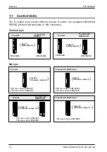
Page 22: ...Chapter 2 Control Units...

Page 23: ...type 2 C14RS terminal type 3 C10CRS with RS232C port terminal type 4 C14CRS with RS232C port terminal type 5 C16T 6 C16P 7 C16CT with RS232C port 8 C16CP with RS232C port 9 C32T 10 C32P 11 C32CT with...

Page 24: ...ct number 1840434 see page 9 12 7 10 Expansion hook is used to secure expansion units The hook is also used for installation on FP0 flat type mounting plate AFP0804 8 Expansion connector connects an e...

Page 25: ...se of the program and the watchdog timer is activated 2 1 2 Mode Switch This switch turns ON and OFF RUN PROG the operation of the FP0 The FP0 can also be turned ON and OFF by the programming tool Swi...

Page 26: ...h pulse widths 50ns and 1 s based on in house measurements Operating condition Free from corrosive gases and excessive dust Operating voltage range 21 6V to 26 4V DC Rated operating voltage 24V DC Rat...

Page 27: ...P C32CP T32CP 60mA or less Expansion I O unit E8X 10mA or less E8YT E8YP 15mA or less E8RS E16RS E16X 20mA or less E16YT E16YP E16T E16P 25mA or less E32T E32P 40mA or less Analog I O unit A21 20mA or...

Page 28: ...ption FP0 E16RS 100mA Type Current consumption FP0 C14RS 100mA FP0 E32T 40mA FP0 E16T 25mA FP0 E16RS 20mA FP Programmer II Ver 2 50mA Total current consumption 235mA or less FP Programmer II Ver 2 C14...

Page 29: ...x 112 max 128 Program memory Built in EEPROM no back up battery required RAM battery back up Program capacity 2 720 steps 5 000 steps 10 000 steps Numbers of instruction Basic instruction 83 types Hig...

Page 30: ...rogram syntax check run time error Memory Timer Non hold type all points Set with backup see notes Counter Non hold type From set value to C139 From set value to C127 system registers 5 Hold type 4 po...

Page 31: ...counting speed 10kHz maximum for all 4 channels see note 4 SInput contacts used SMinimum input pulse width X0 X1 50 s 10kHz X3 X4 100 s 5kHz X0 count input ch 0 X1 count input ch 1 X2 reset input see...

Page 32: ...the reset input for X1 If X3 and X4 are used X5 serves as the reset input for X4 6 With control unit s CPU that is Ver 2 0 or a subsequent version the frequency will be 0 15Hz to 1kHz 2 2 5 Input Spec...

Page 33: ...per common which are simultaneously ON within the following range as determined by the temperature FP0 C14RS C14CRS 8 35 95 55 131 Ambient temperature C F 3 45 113 at 24V DC Number of input points per...

Page 34: ...P C32T C32CT C32P C32CP T32CP Item Description Insulation method optical coupler Output type open collector Rated load voltage NPN open collector type 5 to 24V DC see notes PNP open collector type 24V...

Page 35: ...th different voltages for the load voltage and the external power supply for driving the internal circuit Yn Load Internal circuit External power supply for driving internal circuit 21 6V to 26 4V DC...

Page 36: ...C14CRS Internal circuit X0 Xn COM Y0 Yn COM Power supply Input side Output side 5 6k see note 1 5 6k Internal circuit Internal circuit Internal circuit Load Load see note 1 24V DC see note 2 Notes 1 T...

Page 37: ...CT X0 Xn COM Y0 Yn Load Load 5 6k Internal circuit Input side Output side Internal circuit Internal circuit Internal circuit 24V DC see note 2 24V DC External power supply and load voltage 5 6k see no...

Page 38: ...for driving internal circuit Load for 24V Load for 5V Load for 5V 5V DC Rated load voltage Internal circuit Internal circuit Internal circuit COM 5 6k see note 1 5 6k see note 1 24V DC see note 2 5 6k...

Page 39: ...5 6k Internal circuit Input side Output side Internal circuit Internal circuit Internal circuit 24V DC Load voltage and external power supply see note 1 24V DC see note 2 see note 1 Notes 1 The resis...

Page 40: ...supply X0 5 Y0 3 X0 X5 COM Y0 Y3 COM Load Load see note Y0 3 Power supply Load Load X0 5 2 4 2 C14RS C14CRS see note X0 X7 COM Y0 Y5 COM COM X0 X1 X6 X7 X2 X3 X4 X5 COM Y0 Y1 COM Y5 Y2 Y3 COM Y4 Inpu...

Page 41: ...positive or negative polarity is possible for the input voltage supply 2 The two COM terminals of input terminal X0 7 are connected internally however they should be externally connected as well 2 4...

Page 42: ...er positive or negative polarity is possible for the input voltage supply 2 The four COM terminals of input terminals X0 7 and X8 F are connected internally however they should be externally connected...

Page 43: ...oltage supply 2 The four COM terminals of input terminals X0 7 and X8 F are connected internally however they should be externally connected as well 3 The terminals of output terminals Y0 7 and output...

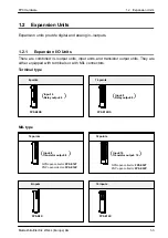
Page 44: ...Chapter 3 Expansion I O Units...

Page 45: ...ansion I O unit types available 1 E8RS terminal type 2 E16RS terminal type 3 E16T 4 E16P 5 E32T 6 E32P 7 E8X input type 8 E16X input type 9 E8YT output type 10 E8YP output type 11 E16YT output type 12...

Page 46: ...x Contact Co product number 1840434 see page 9 12 4 12 Input connector 10 pin 5 14 Output connector 10 pin 6 13 Input connector 10 pin 2 7 15 Output connector 10 pin 2 Use a MIL type connector for the...

Page 47: ...E8X 8 points common E32T E32P E16X 16 points common ON voltage ON current 19 2V or less 3mA or less OFF voltage OFF current 2 4V or more 1mA or more Response time OFF ON 2ms or less at 24V DC and 25...

Page 48: ...input points per common which are simultaneously ON 26 78 8 55 131 34 93 2 3 2 3 Output Specifications Relay Output Type FP0 relay output types E8RS and E16RS Item Description Output type Normally ope...

Page 49: ...E8YP 8 points common E32T E32P E16YT E16YP 16 points common OFF state leakage current 100 A or less ON state voltage drop 1 5V or less External power Voltage 21 6 to 26 4V DC supply for driving inter...

Page 50: ...X20 X2n COM Y20 Y2n COM Power supply Input side Output side 5 6k 1k 5 6k Internal circuit Internal circuit Internal circuit 24V DC see notes Load Load 1k Notes Either positive or negative polarity is...

Page 51: ...l circuit are the same In this set up there is only one power supply FP0 E16T E32T X20 X2n COM Y20 Y2n Load Load 5 6k Internal circuit Input side Output side Internal circuit Internal circuit Internal...

Page 52: ...2n Internal circuit Internal circuit Internal circuit Y20 Y21 Y2n 24V DC External power supply for driving internal circuit Load for 24 V Load for 5 V Load for 5 V 5V DC Rated load voltage Internal ci...

Page 53: ...5 6k 5 6k Internal circuit Input side Output side Internal circuit Internal circuit Internal circuit 24V DC 1k 1k 24V DC see notes Notes Either positive or negative polarity is possible for the input...

Page 54: ...0 E8X E16X Internal circuit X20 X2n COM Input side 5 6k Internal circuit 24V DC notes 5 6k 1k 1k Notes Either positive or negative polarity is possible for the input voltage supply The input number gi...

Page 55: ...tage and external power supply are the same This example is when the values of the rated load voltage and external power supply for driving the internal circuit are the same In this set up there is on...

Page 56: ...e page 7 4 When the load voltage differs from the 24V DC external power supply for driving the internal circuit Other than 24V DC load voltage 5V DC and 12V DC and other load voltages can be connected...

Page 57: ...n the expansion output unit is installed as the first expansion unit see page 7 4 PNP Open Collector Type FP0 E8YP E16YP Y20 Y2F Load Load Output side Internal circuit Internal circuit 24V DC Note The...

Page 58: ...Y21 NC NC Y22 Y23 NC NC Power supply Load Load Load Load Y0 3 X0 3 Notes Either positive or negative polarity is possible for the input voltage supply The I O number given above is the I O number whe...

Page 59: ...tive or negative polarity is possible for the input voltage supply The I O number given above is the I O number when the expansion I O unit is installed as the first expansion unit The I O numbers for...

Page 60: ...location where they are installed see page 7 4 3 4 4 E16P COM X25 X27 X21 X23 COM X24 X26 X20 X22 Y25 Y27 Y21 Y23 Y24 Y26 Y20 Y22 Inputs Outputs A Load Load Load Load Load Load Load A X21 Y21 X20 Y20...

Page 61: ...2 The four COM terminals of input terminals are connected internally however they should be externally connected as well 3 The two terminals of output terminals are connected internally however they...

Page 62: ...The four COM terminals of input terminals are connected internally however they should be externally connected as well 3 The two terminals of output terminals are connected internally however they sho...

Page 63: ...input terminals are connected internally however they should be externally connected as well 3 The input number given above is the input number when the expansion input unit is installed as the first...

Page 64: ...ected as well 3 The input number given above is the input number when the expansion input unit is installed as the first expansion unit The input numbers for the expansion input units will differ depe...

Page 65: ...C Y2E Y28 Y2A A A Outputs Outputs Load Load Load Load Load Load Load Load Load Load Load Load Load Load Load Load Notes The two terminals of the output terminals are connected internally however they...

Page 66: ...erminals of the output terminals are connected internally however they should be externally connected as well The two terminals of the output terminals are connected internally however they should be...

Page 67: ...FP0 Hardware Expansion I O Units 3 24 Matsushita Electric Works Europe AG...

Page 68: ...Chapter 4 Analog I O Unit...

Page 69: ...same range see page 4 3 2 Analog I O terminal 9 pin Use a terminal block socket made by Phoenix Contact Co product number 1840434 see page 4 4 and 9 12 3 6 Expansion hook is used to secure expansion u...

Page 70: ...350 C 100 C to temper ature of terminal 1 2 3 ON 5 Analog output 4 0 to 20mA 10 to 10V range switching ON 4 Notes 1 No averaging Conversion data is set for the specified input contact point area for...

Page 71: ...alog input channel 0 voltage input 2 IN I 0 Analog input channel 0 current input 3 IN COM Analog input channel 0 and 1 analog input common 4 IN V 1 Analog input channel 1 voltage input 5 IN I 1 Analog...

Page 72: ...cycle min double amplitude of 0 75mm 0 030in 10min on 3 axes Shock resistance Shock of 98m s2 or more 4 times on axes Noise immunity 1 000Vp p with pulse widths 50ns and 1 s based on in house measure...

Page 73: ...d between analog inputs Between analog input terminal to analog I O unit external power supply insulation type DC DC converter Between analog input terminal to analog output terminal insulation type D...

Page 74: ...0V Current range 0 to 20mA Digital input 10 to 10V K 2000 to K 2000 HF830 to H07D0 0 to 20mA K0 to K4000 H0 to H0FA0 Resolution 1 4000 Conversion speed 500 s see note 1 Overall precision 1 F S or less...

Page 75: ...in the control unit output Waiting for processing 1ms number of expansion units 10V K0 K2000 0ms to scan time Analog output WY2 0V Refresh Conversion time 500 s 2 Refer to the schematic diagram of ins...

Page 76: ...ess including negative value 0 20mA or more 4000 Corresponding table of A D conversion values Input voltage V A D conversion value 0 0 0 0 5 400 1 0 800 1 5 1200 2 0 1600 2 5 2000 3 0 2400 3 5 2800 4...

Page 77: ...ature of terminal 25 25 250 250 350 350 500 500 750 750 1000 1000 Processing if the range is exceeded Input value Converted value Temperature of terminal or less Temperature of terminal Upper limit 35...

Page 78: ...Corresponding table of A D conversion values Temperature C A D conversion value Temperature of terminal Temperature of terminal 0 0 25 25 50 50 75 75 100 100 Processing if the range is exceeded Input...

Page 79: ...Constant value just before 2001 is input Corresponding table of D A conversion values Digital input value Output current mA 0 0 0 500 2 5 1000 5 0 1500 7 5 2000 10 0 2500 12 5 3000 15 0 3500 17 5 4000...

Page 80: ...V 1 I 1 COM V I COM IN OUT Thermocouple input when measured at temperature higher than the temperature of the terminal Connect IN V terminal to the side of the thermocouple and connect IN COM terminal...

Page 81: ...4 3 Item Output terminal OUT Current terminal I Voltage terminal V 0mA output based on current range setting 0mA 10V 0V output based on voltage range setting 10mA 0V DA internal block diagram A volta...

Page 82: ...FP0 Hardware 4 5 Wiring 4 15 Matsushita Electric Works Europe AG For current output Value of WY K0 K2000 K4000 Digital value to DA converter 0 2047 4095 Analog output 0mA 10mA 20mA...

Page 83: ...K200 K207 Digital value WX2 Measured value Logical Value Offset error R9010 F27 WX2 K7 DT100 Program example FPWIN GR In the above case seven should be subtracted from the value of WX2 The value with...

Page 84: ...1800 100 min 1850 1900 1830 1870 1780 1810 1800 100 min 1850 1900 1830 1870 110 100 1800 90 min 100 1910 max 100 110 100 1800 1850 1900 1830 1870 8 1195 110 100 1800 1850 1900 1830 1870 1780 8 1405 1...

Page 85: ...ax 100 100 1000 3 400 100 1000 1000 1000 max 100 1000 1000 3 700 1000 1000 1000 max 1000 1000 1000 3 1000 90 min 90 min 100 min 1000 Averaging of results from 3 times with maximum minimum values delet...

Page 86: ...Averaging Function 4 19 Matsushita Electric Works Europe AG ch1 ch0 ch1 Data from 8 times used for averaging Check for disconnected wiring 70msec 70msec If a disconnected wire is detected a value of...

Page 87: ...FP0 Hardware Analog I O Unit 4 20 Matsushita Electric Works Europe AG...

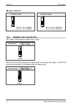
Page 88: ...Chapter 5 FP0 I O Link Unit MEWNET F...

Page 89: ...unit is sent to the input of the FP0 through the FP0 I O Link Unit The output from the FP0 is sent to the input of the master unit from the FP0 I O Link Unit Be sure to connect the FP0 I O Link Unit...

Page 90: ...be impossible Note In case of a selection error the ALARM LED will flash 5 1 3 Operation Mode Selection Switches Switch No Function OFF ON 1 2 Terminal station selection Not a terminal station Operat...

Page 91: ...nk Unit Be careful not to leave wire wastes inside the units when wiring Do not touch the unit s expansion connector with your hand This may result in a poor contact and the static electricity from yo...

Page 92: ...y function earth terminals AC500V 1minute Insulation resistance RS485 terminals Power supply function earth terminals min 100M measured with a 500V DC megger Vibration resistance 10Hz to 55Hz 1 cycle...

Page 93: ...aster unit Ver Ver 1 5 or higher Max 4 096 points Number of I O points per one I O Link unit 64 points Input 32 points Output 32 points see note Note If the I O Link error flag is on valid there are 6...

Page 94: ...specially be used in an environment with extensive noise 5 If AFP3740 AFP87441 AFP87442 AFP3741 are in the network the communication distance should be limited as stated above 5 3 5 Terminal Pin Layou...

Page 95: ...FP 2 Multi Wire Link Unit FP2 MW ster tion FP3 Remote I O Master Unit AFP3742 Ma sta FP C CPU with MEWNET F Board AFC3224 FP C MEWNET F Master Board AFC3740 Slave Unit FP3 Remote I O Slave Unit AFP374...

Page 96: ...ication Error Output Mode If the communication error occurs in the Remote I O System the FP0 I O Link Unit will select either the Output OFF or Output HOLD mode In the case below the output of the FP0...

Page 97: ...ut of the FP3 FP10SH from the FP0 I O Link Unit Be sure to connect the FP0 I O Link Unit with one FP3 FP10SH Master Unit Without a master station the slave station including FP0 I O Link Unit will not...

Page 98: ...ns on This flag is assigned the MSB most significant bit of Input 2 words 32bits WX n n 1 in the FP0 I O Link Unit For details see page 5 11 Example 1 5 4 5 I O Number Example 1 Below is an example of...

Page 99: ...X68 and 69 X680 to 69F and the output number is WY70 and 71 Y700 to 71F The relationship between the input output of the FP3 FP10SH and that of the FP0 from the illustration above is shown below FP3 F...

Page 100: ...flag The difference from example 1 is that the MSB most significant bit of 2 words input here X3F is the I O Link error flag This error flag indicates the communication condition between this I O Link...

Page 101: ...nit WY2 3 WX2 3 WY4 5 WX4 5 WY6 7 WX6 7 WY2 3 WX2 3 WY64 65 WX66 67 WY68 69 WX70 71 WY72 73 WX74 75 WY76 77 WX78 79 1st expansion Station No 1 2nd expansion Station No 2 3rd expansion Station No 3 1st...

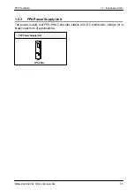
Page 102: ...Chapter 6 Power Supply Unit...

Page 103: ...Power Supply Unit FP0 PSA2 1 LED is ON when the output is on 2 24V DC output terminals 0 7A 3 0V DC output terminals 0 7A 4 N 100 240V AC input terminal 0 4A 5 L 100 240V AC input terminal 0 4A 6 DIN...

Page 104: ...witch off at 0 8A and more Holding time min 20ms at 230V AC General Specifications Characteristics primary switched temperature and current peak controlled Ambient temperature 0 C 32_F to 55 C 131_F S...

Page 105: ...FP0 Hardware Power Supply Unit 6 4 Matsushita Electric Works Europe AG...

Page 106: ...Chapter 7 I O Allocation...

Page 107: ...oints they are expressed as a combination of decimal and hexadecimal numbers as shown below Example External input relay X Decimal 1 2 3 Hexadecimal 0 1 2 3 A B F X0 X1 XF X10 X11 X1F X20 X21 X2F Spec...

Page 108: ...P0 control unit is fixed Type I O number C10RS C10CRS Input 6 points X0 to X5 Output 4 points Y0 to Y3 C14RS C14CRS Input 8 points X0 to X7 Output 6 points Y0 to Y5 C16T C16CT C16P C16CP Input 8 point...

Page 109: ...nsion E8RS Input 4 points X20 to X23 X40 to X43 X60 to X63 Output 4 points Y20 to Y23 Y40 to Y43 Y60 to Y63 E8X Input 8 points X20 to X27 X40 to X47 X60 to X67 E8YT E8YP Output 8 points Y20 to Y27 Y40...

Page 110: ...is determined by the installation location I O number Type First expansion Second expansion Third expansion A21 Input channel 0 16 points WX2 X20 to X2F WX4 X40 to X4F WX6 X60 to X6F Input channel 1 1...

Page 111: ...FP0 Hardware I O Allocation 7 6 Matsushita Electric Works Europe AG 7 5 Link Unit For explanations and examples on I O allocation for the FP0 I O Link Unit see page 5 11...

Page 112: ...Chapter 8 Installation...

Page 113: ...ng alkaline solutions such as ammonia or caustic soda Excessive vibration or shock Direct sunlight Water in any form including spray or mist Avoid noise interference from the following items Influence...

Page 114: ...blocks the air duct Installations such that the I O connectors or I O terminals face down Horizontal installation of the unit Do not install the unit above devices which generate heat such as heaters...

Page 115: ...3 937in between devices to avoid adverse affects from noise and heat when installing a device or panel door to the front of the FP0 unit 100mm 3 937in or more Other device or panel door FP0 Keep the f...

Page 116: ...shaded part is exposed Cut off the shaded part with a pair of nippers or similar tool so that the internal connector is exposed Cut here Shaded part When removing the shaded part use a sharp cutting o...

Page 117: ...AG 3 Align the pins and holes in the four corners of the control unit and expansion unit and insert the pins into the holes so that there is no gap between the units Control unit Expansion unit 4 Pres...

Page 118: ...N rail 2 Without moving the upper hook press on the lower hook to fit the FP0 unit into position DIN rail FP0 unit Mounting panel 1 2 You can easily remove the FP0 unit as described below Procedure 1...

Page 119: ...type mounting plate Screw Screw Procedure 1 Fit the upper hook of the FP0 unit onto the FP0 slim type mounting plate 2 Without moving the upper hook press on the lower hook to fit the FP0 unit into p...

Page 120: ...For a diagram showing detailed dimensions of the FP0 flat type mounting plate see page D 11 Mounting panel 60 mm 2 362in screws FP0 flat type mounting plate Procedure 1 Raise the expansion hooks on th...

Page 121: ...rdware Installation 8 10 Matsushita Electric Works Europe AG An FP0 unit with an attached FP0 flat type mounting plate can also be installed sideways on a DIN rail DIN rail FP0 flat type mounting plat...

Page 122: ...Chapter 9 Wiring...

Page 123: ...a system shutdown or an irreparable accident when malfunction occurs 9 1 3 Start Up Sequence The FP0 should be operated after all of the outside devices are energized To keep this sequence the follow...

Page 124: ...non insulated circuit so if an incorrect voltage is directly applied the internal circuit may be damaged or destroyed If using a power supply without a protective circuit power should be supplied thr...

Page 125: ...iptions Rated voltage 24V DC Operating voltage range 21 6 to 26 4V DC Notes To minimize adverse effects from noise twist the brown and blue wires of the power supply cable To protect the system agains...

Page 126: ...ted DC power supply The power supply sequence should be set up so that power to the control unit is turned OFF before the input output power supplies If the input output power supplies are turned OFF...

Page 127: ...ontrol unit as possible The ground wire should be as short as possible If two devices share a single ground point it may produce an adverse effect Always use an exclusive ground for each device Depend...

Page 128: ...100mm 3 937in In this section you find some examples for wiring sensors an LED equipped reed switch a two wire type sensor and a LED equipped limit switch 9 4 1 Sensors Relay output type NPN open coll...

Page 129: ...ecommended as shown below The OFF voltage of the FP0 input is 2 4V therefore select an R value so that the voltage between the COM terminal and the input terminal will be less than 2 4V The impedance...

Page 130: ...input is 2 4V therefore when the power supply voltage is 24V select R so that the current will be greater than I The resistance R of the bleeder resistor is R The wattage W of the resistor is W In the...

Page 131: ...t wiring are separated and so that the output wiring is separated from the power wiring as much as possible Do not route them through the same duct or wrap them up together Separate the output wires f...

Page 132: ...es the load voltage Average rectified forward current I0 Load current or more Diode COM Output terminal Diode 9 5 2 Precautions for Using Capacitive Loads When connecting loads with large in rush curr...

Page 133: ...0 3 to 1 25mm2 Analog I O unit Size AWG 28 to 16 Conductor cross sectional area 0 08 to 1 25mm2 Pole terminal with a compatible insulation sleeve If a pole terminal is being used the following models...

Page 134: ...place Clockwise Wire Notes When removing the wire s insulation be careful not to scratch the core wire Do not twist the wires to connect them Do not solder the wires to connect them The solder may bre...

Page 135: ...AXW61001 2 pieces 4 pieces Welder contact AXW7221 5 pin 4 5 pin 8 Suitable wires twisted wire Size Conductor cross sectional area Insulation thickness Rated current AWG 22 0 3mm2 AWG 24 0 2mm2 dia 1...

Page 136: ...nector for flat cables please specify the order number AXM110915 9 7 1 Contact Puller Pin for Rewiring If there is a wiring mistake or the cable is incorrectly pressure connected the contact puller pi...

Page 137: ...412 RS232C port is not used 413 Character bit 8 bits Parity check odd Stop bit 1 bit Header without STX code Terminator CR 414 Baud rate 9600bps Suitable wires twisted wire Size AWG 28 to 16 Conducto...

Page 138: ...wire s insulation be careful not to scratch the core wire Do not twist the wires to connect them Do not solder the wires to connect them The solder may break due to vibration After wiring make sure st...

Page 139: ...FP0 Hardware Wiring 9 18 Matsushita Electric Works Europe AG...

Page 140: ...Chapter 10 Trial Operation...

Page 141: ...will return to normal when the load returns to normal be careful as long overloads or shortcircuits will cause deterioration or destruction of internal elements see note S When output voltage decreas...

Page 142: ...the FP programmer II Ver 2 Use the programming tool s total check function to check for syntax errors 5 Check output wiring Use the forced output function to check the output wiring 6 Check input wir...

Page 143: ...FP0 Hardware Trial Operation 10 4 Matsushita Electric Works Europe AG...

Page 144: ...Chapter 11 Self Diagnostic and Troubleshooting...

Page 145: ...ink When a self diagnostic error Operation Abnormal OFF ON Blink When a self diagnostic error occurs Stop Abnormal condition Varies Varies ON When a system watchdog timer error occurs Stop Normally if...

Page 146: ...shown on the right is displayed READ 1 ENT ACLR OP SLF DIAGN ERR CD Error code Content of error 1 0 Check the error code using the programming tool Procedure 1 Using FPWIN GR In the ONLINE mode select...

Page 147: ...ibed on the pre vious page Using FP programmer II Press the keys as shown on the right Error code 43 and higher can be cleared Using FPWIN Pro Monitor PLC Status Click Clear D In the PROG mode the pow...

Page 148: ...ck D if instructions such as JP or LOOP are programmed in such a way that a scan can never finish D that interrupt instructions are executed in succession Procedure 1 Procedure 2 11 2 3 All LEDs are O...

Page 149: ...ON the output using a programming tool If the output indicator LED is turned ON go to input condition check If the output indicator LED remains OFF there is probably an abnormality in the FP0 s outpu...

Page 150: ...itored is OFF there is probably an abnormality in the FP0 s input circuit Please contact your dealer If the input monitored is ON check the program again Also check the leakage current at the input de...

Page 151: ...the baud rate as shown below TRNS RATE bps 115k 57k 38k 19200 9600 4800 2400 Select a baud rate 9600 press F1 and select SAVE DISK YES to regis ter this change onto the disk Using FPWIN GR Option Com...

Page 152: ...kip to the PLC CONFIGURATION window In the PLC CON FIGURATION window select SET PLC PASSWORD Enter the password and select enable ENAB Procedure Using NPST GR software Using FPWIN GR Tool Set PLC Pass...

Page 153: ...and eliminates the possibility of incorrect operation from syntax check errors in the program When a syntax check error is detected ERROR ALARM LED begins blinking Operation will not begin even after...

Page 154: ...tops Two or more OT Out instructions and KP Keep instructions are programmed using the same relay This error also occurs if you have the same timer counter numbers Correct the program so that one rela...

Page 155: ...e Turn OFF the power and check the noise conditions E32 Interrupt error 2 Stops An interrupt occurred without an interrupt request A hardware problem or error due to noise is possible Turn OFF the pow...

Page 156: ...Appendix A System Registers...

Page 157: ...er supply interruption are fixed and the settings for system register 6 to 8 and 14 will be invalid Operation mode settings for errors System register 20 23 26 and 27 Set the operation mode effective...

Page 158: ...YSTEM REGISTER in PLC CONFIGURATION screen The value set in the selected system register will appear 4 To change a set value write the new value as indicated in the system register table 5 Execute Reg...

Page 159: ...Timer 100 points No 0 to No 99 Counter 44 points No 100 to No 143 Setting example To increase the number of timers to 120 change the value of system register 5 to K120 Set value n Timer Counter MIN 0...

Page 160: ...127 Hold type 16 points elapsed values C128 to C143 Internal relay Non hold type 880 points R0 to R54F 55 words WR0 to WR54 Hold type 128 points R550 to R62F 8 words WR55 to WR62 Data register Non hol...

Page 161: ...ty The set values are fixed and cannot be changed The stored values vary depending on the model and type K3 3 K words FP0 C10 C14 C16 K5 5 K words FP0 C32 1 to 3 Unused Hold Non hold 5 Timer and count...

Page 162: ...i frame communica tion ms In FPWIN Pro or NPST GR enter the time a number divisible by 2 5 In FP Programmer II enter the set value equal to the time divided by 2 5 32 33 Unused With the FP0 values set...

Page 163: ...t X2 7 Individual input X0 X1 8 Individual input X0 X1 Reset input X2 9 Direction decision X0 X1 10 Direction decision X0 X1 Reset input X2 CH1 0 Do not set input X1 as high speed count er 3 Increment...

Page 164: ...X2 7 Individual input X0 X1 8 Individual input X0 X1 Reset input X2 9 Direction dicision X0 X1 A Direction dicision X0 X1 Reset input X2 0 Do not use high speed counter 3 Incremental input X1 4 Incre...

Page 165: ...ut X5 7 Individual input X3 X4 8 Individual input X3 X4 Reset input X5 9 Direction decision X3 X4 10 Direction decision X3 X4 Reset input X5 CH3 0 Do not set input X4 as high speed counter 3 Increment...

Page 166: ...t X5 7 Individual input X3 X4 8 Individual input X3 X4 Reset input X5 9 Direction dicision X3 X4 A Direction dicision X3 X4 Reset input X5 0 Do not use high speed counter 3 Incremental input X4 4 Incr...

Page 167: ...and X0 and X1 are set as interrupt inputs when going from on to off FP programmer II Specify the input con tacts used as interrupt inputs in the upper byte Using NPST GR ver 4 0 Standard input 1 Inte...

Page 168: ...Modem communication Disabled SData length character bits 8 bits H0 When connecting a modem set the unit num ber to 1 with system resister 410 Modem communication 0 Disabled 1 Enabled Data length chara...

Page 169: ...setting contents using H constants 15 0 6 Data length 0 7 bits 1 8 bits Parity check 00 None 01 With odd 11 With even Start code 0 No STX 1 STX Terminal code 00 CR 01 CR LF 10 None 11 ETX Stop bit 0...

Page 170: ...Appendix B Special Internal Relays...

Page 171: ...t when the compared results become larger in the F60 CMP to F63 DWIN comparison instructions R900B flag Turns on for an instant when the compared results are equal in the comparison instructions F60 t...

Page 172: ...lay Repeats on off operations in 2s cycles on off 1s 1s 2s R901E 1min clock pulse relay Repeats on off operations in 1 min cycles on off 30s 30s 1min R901F Not used R9020 RUN mode flag Turns off while...

Page 173: ...9038 RS232C reception completed flag Turns on when a terminator is received during the serial data communicating R9039 RS232C transmission completed flag Turns on while data is not send during the ser...

Page 174: ...Appendix C Special Data Registers...

Page 175: ...occurred is stored in bits 0 to 3 DT90014 DT9014 Auxiliary register for operation One shift out hexadecimal digit is stored in bit positions 0 to 3 when an F105 BSR or F106 BSL instruction is executed...

Page 176: ...using ICTL instruction can be moni tored here Monitor using binary display 0 interrupt disabled masked 1 interrupt enabled unmasked 15 11 7 3 0 Bit No 23 19 16 INT No DT90026 DT9026 Not used DT90027 D...

Page 177: ...0 The target value 24 bit data of the high speed counter specified by the high speed counter instruction is stored here DT90047 DT9047 counter instruction is stored here Target values have been preset...

Page 178: ...9052 are allocated in groups of four to high speed channels 0 to 3 as shown below Control code Binary Software reset 0 Yes 1 No Count 0 Enable 1 Disable Hardware reset 0 Enable 1 Disable High speed co...

Page 179: ...timer is stored The built in calendar timer will operate cor rectly through the year 2099 and supports leap years The calendar timer can be set the time set by writing a value using a programming tool...

Page 180: ...R software the time will be set when the new values are written Therefore it is unnecessary to write to DT90058 When the correcting times less than 30 seconds By setting the lowest bit of DT90058 to 1...

Page 181: ...Other Types DT90059 DT9059 bit 15 0 Error flag of RS232C port 3 4 7 8 11 12 DT90059 DT9059 Error flag of tool port STool port bit 0 1 Over run error bit 1 1 Framing error bit 2 1 Parity error SRS232C...

Page 182: ...an be written by executing a DMV F1 instruction DT90106 DT9106 High speed counter target value area for ch2 The target value 24 bit data of the high speed counter specified by the high speed counter i...

Page 183: ...FP0 Hardware Special Data Registers C 10 Matsushita Electric Works Europe AG...

Page 184: ...Appendix D Dimensions...

Page 185: ...ric Works Europe AG D 1 C10RS 10CRS 14RS 14CRS E8RS 16RS 60 0 2 362 90 0 3 543 25 0 0 984 Approx 100 0 3 937 60 0 2 362 90 0 3 543 Approx 130 0 5 118 7 5 0 295 DIN rail DIN EN50022 35 1 378 attachment...

Page 186: ...16P 16CP E16T 16P 8X 8YT 8YP D 3 Matsushita Electric Works Europe AG D 2 C16T 16CT 16P 16CP E16T 16P 8X 8YT 8YP Approx 78 0 3 071 60 0 2 362 90 0 3 543 3 5 0 138 60 0 2 362 90 0 3 543 25 0 0 984 unit...

Page 187: ...e Dimensions D 4 Matsushita Electric Works Europe AG D 3 C32T 32CT 32P 32CP E32T 32P 16X 16YT 16YP Approx 78 0 3 071 60 0 2 362 90 0 3 543 3 5 0 138 60 0 2 362 90 0 3 543 30 0 1 181 unit mm in 3 5 0 1...

Page 188: ...FP0 Hardware D 4 Analog I O Unit D 5 Matsushita Electric Works Europe AG D 4 Analog I O Unit 60 0 2 362 90 0 3 543 25 0 0 984 unit mm in 3 5 0 138...

Page 189: ...FP0 Hardware Dimensions D 6 Matsushita Electric Works Europe AG D 5 I O Link Unit 60 0 2 362 90 0 3 543 unit mm in 3 5 0 138 25 0 0 984...

Page 190: ...FP0 Hardware D 6 Power Supply Unit D 7 Matsushita Electric Works Europe AG D 6 Power Supply Unit 4 5 0 177 30 4 1 197 60 0 2 362 90 0 3 543 8 5 0 335 90 0 3 543 unit mm in...

Page 191: ...3 D B A DIN rail DIN rail unit mm in Note A B C D dimensions Unit mm in Control unit type A Control unit only A B 1 expansion unit connected A B C 2 expansion units connected A B C D 3 expansion units...

Page 192: ...0 0 394 dir 5 0 0 197 3 5 0 138 2 5 0 098 unit mm in unit mm in Figure 1 One plate 90 0 3 543 100 3 937 60 0 2 362 dir 10 0 0 394 25 0 0 984 60 0 2 362 dir 5 0 2 362 75 0 2 953 dir 5 0 0 197 25 0 0 9...

Page 193: ...FP0 Hardware Dimensions D 10 Matsushita Electric Works Europe AG D 8 1 Dimensions When Using FP0 Slim Type Mounting Plate 60 0 2 362 70 0 2 756 unit mm in...

Page 194: ...1 dir 5 0 0 197 dir 10 0 0 394 2 2 0 087 4 0 0 157 unit mm in Unit type A mm in B mm in C10RS C10CRS C14RS C14CRS C16T C16CT C16P C16CP 31 2 1 23 25 0 98 C32T C32CT C32P C32CP 36 2 1 43 30 1 18 Note C...

Page 195: ...FP0 Hardware Dimensions D 12 Matsushita Electric Works Europe AG...

Page 196: ...output specifications 2 13 relay output 2 13 transistor output type 2 13 parts and terminology 2 2 performance specifications 2 8 pin layouts 2 19 RS232C port 2 4 specifications 2 5 terminal type 1 2...

Page 197: ...tools 1 9 PROTECT ERROR 11 9 R Relay output units combinations 1 7 RS232C port baud rate 9 16 wires 9 16 wiring 9 16 S Safety instructions wiring 9 2 Self diagnostic error 11 11 Self diagnostic error...

Page 198: ...iptions for FP0 analog I O unit is added ACGM0084END V3 1 Jan 1999 European edition Molex type units removed T32CP control unit information added power supply unit information added AGGM0084END V3 2 S...

Page 199: ...ax 46 8 59 47 66 90 http www mac europe com H Spain Matsushita Electric Works Espa a S A Parque Empresarial Barajas San Severo 20 28042 Madrid Spain Tel 91 329 38 75 Fax 91 329 29 76 H Switzerland Mat...

Reviews: