
1
GEM-PX
Proximity Reader
Installation Instructions
R
333 Bayview Avenue
Amityville, New York 11701
For Sales and Repairs, (800) 645-9445
For Technical Service, (800) 645-9440
Publicly traded on NASDAQ Symbol: NSSC
© NAPCO 2004
WI1269B 10/04
GENERAL DESCRIPTION
The GEM-PX is a NAPCO proprietary proximity card reader
which combines with the GEM-PXCV cover to provide com-
plete system status using indicator LED’s. The GEM-PX
reader can only be used with GEM 36-bit proprietary prox-
imity cards. The GEM-PX reader consists of the proximity
reader module, which is fully encapsulated in weather resis-
tant potting and the snap on GEM-PXCV cover which
houses additional LED’s. The multicolored LED on the
GEM-PX provides standard visual feedback as to
access
condition
(door “locked” or “unlocked”), and the additional
LED’s in the GEM-PXCV cover provide feedback as to
sys-
tem condition
(system “armed” or “disarmed”). Together,
the GEM-PX and GEM-PXCV is an indoor/outdoor prox-
imity card reader providing potted electronics, low power
consumption and durability all in a small, easy to install
package.
SPECIFICATIONS
12V Nominal, 50mA standby current.
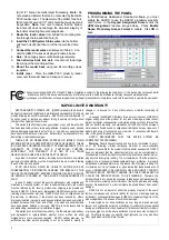
LED Indications
The GEM-PX reader contains a multicolored LED which
provides visual feedback
as to access condition
when access cards are
presented to the reader.
Table 1 below displays
the LED indications and
their meanings.
The GEM-PXCV pro-
vides two LED's to indi-
cate system condition,
as displayed in Table 2
below:
Stealth Mode
is used to hide the ACM’s Armed and Status
LEDs. When
Stealth Mode
is enabled, the GEM-PXCV
system status LEDs are normally off but are turned on for 1
minute by any of the following events:
•
Press a request to exit button
•
Press a request to arm button
•
Present a valid ARM/DISARM or ARM card to the
reader
When Stealth Mode is disabled ("normal operation"), the
LED's are always enabled and mimic the Keypad Status
LEDs for the following functions only:
Armed
,
Disarmed
,
Ready to Arm
,
Not-Ready to Arm
and
Alarm
.
Note:
When
the system is in alarm, Stealth Mode is disabled. "Access
Only" cards do not affect the status of Stealth Mode.
MOUNTING THE GEM-PX
Before mounting the card reader, always plan ahead and deter-
mine the route all wires will follow before drilling into wall mount-
ing surfaces. For more information regarding various system
designs, refer to WI1121 for complete installation instructions.
Install the GEM-PX as follows:
1.
Determine mounting location.
Using the template
(Figure 1) and a pencil, lightly mark the location of the two
mounting holes and the two wire feed holes.
2.
Route the Reader Wires.
The minimum number of wires
required to activate the reader are displayed in Table 3.
Determine which wires will be needed and plan how these
wires will be accessed from behind the mounting location.
3.
Install dry wall mounting hardware.
Use hardware such
as molly bolts, toggle bolts or other anchoring devices.
Drill the smallest hole needed for the device.
Warning:
Use caution when drilling holes--there may be high voltage
wiring in wall.
4.
Drill wire feed holes.
Minimum size for the top feed hole
Table 1: Access Status LED (Top)
LED INDICATION
ACCESS CONDITION
Steady Red
Door Locked
Steady Green
Door Unlocked
Alternating Green & Red
(Downloading PCD-Windows Program to ACM)
Momentary Green
Card Read--Door Remains Locked
Table 2: System Status LED's (Bottom)
LED INDICATION
SYSTEM CONDITION
Steady Red
System Armed
Red LED is off
System Disarmed
Blinking Red
System in Alarm
Steady Green
System Ready to Arm
Green LED is off
System Not Ready to Arm
Table 3: Proximity Card Reader Connections
GEM-ACM1D Termi-
nal Number
GEM-ACM1D Terminal
Description
HID Model 6005B (Prox Point
Plus ) Wires
17 (+)
Reader Power
Red (+ DC)
18 (-)
Reader Power
Black (- Ground) & (Shielded
Ground)
19
Reader Data 1
White (Data 1)
20
Reader Data 0
Green (Data 0)
21 (-)
Red LED
Brown (Red LED)
22 (-)
Red & Green LED
Orange (Green LED)
23 (-)
Reader Sounder
Yellow (Beeper)
(Not Used)
(Not Used)
Blue (Hold)
(Not Used)
(Not Used)
Violet (Card Present)
* Tamper Connection not available on HID 6005B
Be sure to place jumper JP1 in correct configuration for 5 volt of 12 volt reader
operation.
Table 4: GEM-PX Wire Connections
GEM-PX Wires
GEM-ACM1D
Terminal
Description
GEM-ACM1D
Terminal Number
GEM-2D Terminal
Number
Red
Reader Power
17 (+)
35 (+)
Orange
Active Low Red
Armed LED
30
48
Green
Status Green LED
31
49
Access
Status LED
(see table 1)
System
Status LED's
(see table 2)


