FRENCH
PG. 55
W415-2348 / B / 01.22.20
ADD MANUAL TITLE
Wolf Steel Ltd., 24 Napoleon Rd., Barrie, ON, L4M 0G8 Canada / 103 Miller Drive, Crittenden, Kentucky, USA, 41030
Phone 1 (866) 820-8686 • www.napoleon.com • hearth@napoleon.com
CERTIFIED TO THE CANADIAN AND AMERICAN NATIONAL STANDARDS:
CSA 2.22 AND ANSI Z21.50 FOR VENTED DECORATIVE GAS APPLIANCES
INSTALLER:
Leave this manual with the appliance
CONSUMER:
Retain this manual for future reference
ADD PRODUCT CODE HERE (TRADE GOTHIC LT STD FONT)
NATURAL GAS MODELS:
PROPANE GAS MODELS:
Product Name / Code
(MUST use title from Price Book)
ADD ____ ILLUSTRATED
ADD PRODUCT IMAGE
CSA /
INTERTEK
LOGO
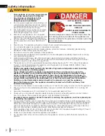
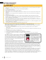
SAFETY INFORMATION
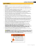
- Do not store or use gasoline or other
fl ammable vapors and liquids in the vicinity of
this or any other appliance.
-
WHAT TO DO IF YOU SMELL GAS
:
•
Do not try to light any appliance.
•
Do not touch any electrical switch; do not
use any phone in your building.
•
Immediately call your gas supplier from a
neighbour’s phone. Follow the gas
supplier’s instructions.
•
If you cannot reach your gas supplier, call
the fi re department.
- Installation and service must be
performed by a qualifi ed installer, service
agency, or the supplier.
This appliance may be installed in an aftermarket,
permanently located, manufactured home (USA
only) or mobile home, where not prohibited by
local codes.
This appliance is only for use with the type of gas
indicated on the rating plate. This appliance is
not convertible for use with other gases, unless
a certifi ed kit is used.
FIRE OR EXPLOSION HAZARD
Failure to follow safety warnings exactly
could result in serious injury, death, or
property damage.
WARNING
!
ENGLISH
$10.00
FOR INDOOR USE ONLY
IF INSTAL OPERATION, ADD SERIAL
NUMBER LABEL HERE
IF SEPARATE MANUALS, ADD “PLACE
BARCODE LABEL ON THE OWNER’S MANUAL”
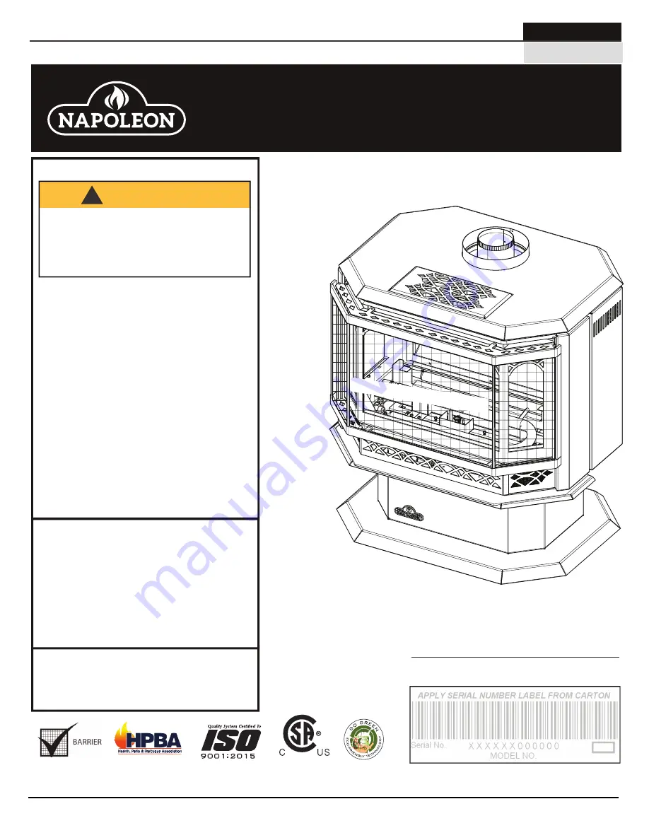
Model GS50 is made up of Model GDS50 and
Natural Vent Adapter Kit GS-150KT
INSTALLATION AND
OPERATION MANUAL
GDS50-1NSB / GDS50-1NE / GS50-1N / GS50-1NE
GDS50-1PSB / GDS50-1PE / GS50-1P / GS50-1PE
Havelock™
(GDS50-1 illustrated)
SAFETY BARRIER