FUEL CONVERSION KIT FOR ELECTRONIC IGNITION MODELS
(C)HD35 / (C)HD40 / (C)HD46
These kits are for use at altitudes of 0 to 4500 feet.
INSTALLER: THESE INSTRUCTIONS ARE TO REMAIN WITH THE HOME OWNER.
CHECK THE BOXES TO INDICATE THAT THE CORRESPONDING STEPS HAVE BEEN COMPLETED.
!
WARNING
Wolf Steel Ltd., 24 Napoleon Rd., Barrie, ON L4M 0G8 Canada • (705)721-1212 • fax (705)720-9081 • www.napoleonfireplaces.com
WARNING: Failure to position the parts in accordance with these diagrams or failure to use only parts specifically approved with this
appliance may result in property damage or personal injury.
CAUTION: Before proceeding with conversion shut off gas supply and disconnect electrical power.
LOG SUPPORT
SCREWS
BURNER PAN
MOUNTING
SCREWS
Kit W175-0304, Natural Gas to Propane Includes;
1 REGULATOR
1
#54 BURNER ORIFICE
1
CONVERSION DATA LABEL
1
PILOT INJECTOR
(C)HD35
Kit W175-0286, Natural Gas to Propane Includes;
1 REGULATOR
1
#53 BURNER ORIFICE
1
CONVERSION DATA LABEL
1
PILOT INJECTOR
Kit W175-0288, Natural Gas to Propane Includes;
1 REGULATOR
1
#52 BURNER ORIFICE
1
CONVERSION DATA LABEL
1
PILOT INJECTOR
Kit W175-0284, Propane to Natural Gas Includes;
1 REGULATOR
1
#42 BURNER ORIFICE
1
CONVERSION DATA LABEL
1
PILOT INJECTOR
Kit W175-0285, Propane to Natural Gas Includes;
1 REGULATOR
1
#38 BURNER ORIFICE
1
CONVERSION DATA LABEL
1
PILOT INJECTOR
Kit W175-0287, Propane to Natural Gas Includes;
1 REGULATOR
1
#37 BURNER ORIFICE
1
CONVERSION DATA LABEL
1
PILOT INJECTOR
This conversion kit shall be installed by a qualified service agency in accordance with the manufacturer’s instructions and all
applicable codes and requirements of the authority having jurisdiction. If the information in these instructions is not followed
exactly, a fire, explosion or production of carbon monoxide may result causing property damage, personal injury or loss of life.
The qualified service agency is responsible for the proper installation of this kit. The installation is not proper and complete
until the operation of the converted appliance is checked as specified in the owner instructions supplied with the kit.
BURNER
ORIFICE
PILOT BRACKET
SCREWS
Purge all gas lines with the glass door open.
Assure that a continuous flow is at the burner before closing the door.
W415-0980 / B / 10.31.16
(C)HD40
(C)HD46
(C)HD35
(C)HD40
(C)HD46
PILOT
ORIFICE
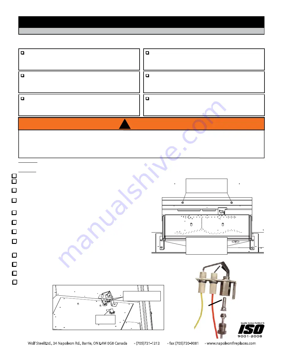
1. Open the glass viewing door and remove the log set.
2. Remove the 2 screws from the firebox back to remove the log
support.
(FIG. 1)
3. To remove the burner pan, remove the 4 securing screws indicated,
slide it to the left and lift out.
(FIG. 1)
4. Remove the 2 screws from the pilot bracket.
(FIG.2)
Using a wrench,
remove the pilot tube fitting from the pilot assembly. Replace the pilot
orifice with the one supplied. Re-assemble in reverse order.
(FIG.3)
5. Using a deep socket wrench, remove the main burner orifice.
Replace with the orifice supplied.
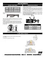
6. Before repositioning the burner assembly, change the burner shutter
setting according to the venturi adjustment table.
7. Reposition and re-secure the burner assembly ensuring that the
venturi fits over the burner orifice.
8. To convert the main valve, follow the instructions that are supplied
with the regulator assembly kit.
IMPORTANT: Use the screws
removed from the valve to secure.
9. The conversion data label must be filled out and attached adjacent to
the valve.
10.
Turn on the gas supply and check for gas leaks by brushing soap and water solution.
Do not
use open flame.
11.
Replace the log set. Then light the pilot and main burner to ensure that the gas lines have
been purged.
12. Close the glass viewing door. Turn on the electrical supply to the appliance.
FIG.2
FIG.3
FIG.1


