background image

INSTRUCTIONS BOOK 

PRADA NARGESA, S.L 

Ctra. de Garrigàs a Sant Miquel s/n · 17476 Palau de Santa Eulàlia (Girona) Spain 

Tel. +34 972568085 · nargesa@nargesa.com · www.nargesa.com 

GAS FORGE 

H3 

Summary of Contents for H3

Page 1: ...INSTRUCTIONS BOOK PRADA NARGESA S L Ctra de Garrig s a Sant Miquel s n 17476 Palau de Santa Eul lia Girona Spain Tel 34 972568085 nargesa nargesa com www nargesa com GAS FORGE H3...

Page 2: ...Thank you for choosing our machines www nargesa com...

Page 3: ...enance 10 3 2 Change of the insulating material of the furnace 11 4 HANDLING BOOK 16 4 1 Gas valve 16 4 2 Pushbuttons 16 4 3 Pressure controller and manometer 16 5 INSTALLATION AND SET UP 17 5 1 Locat...

Page 4: ...re of 1300 C The oven is composed of three elements supplied by Nargesa the oven the Gas hose and the Pressure regulator This type of installation will never be modified in No Case The oven is equippe...

Page 5: ...s fact Spray with w ter mist the containers exposed to fire This devide should be remotely controlled and so after the fire extintion Fight the fire aains the wind direction whenever it is posible Do...

Page 6: ...ge Presure control device Adapter The Adapter for the gas bottle is NOT provided along with the furnace because of the major differences according to each country The Adapter must be equipped with a m...

Page 7: ...rmediate part of the bar we will open the two lateral openings of the oven so that the bar can pass through the inside of the oven and thus be able to heat the desired part Picture 2 Furnace openings...

Page 8: ...e pushbutton for ignition of the furnace In the process of ignition of the furnace we press this button to allow the passage of gas When the thermo couple gets enough temperature we will release this...

Page 9: ...res Dimensions of combustion chamber 464x240x100 mm Maximum temperature 1300 C Nr of burners 3 Type of fuel Propane gas GLP Adjustable working pressure 0 1 1 5 bar Power Hi 12 kW Gas intake as 1 per b...

Page 10: ...ifting it with both hands Do not transport the furnace in any other way since it could be damaged Picture 6 Transport of the machine 2 2 Storage conditions The furnace cannot be stowed in a place that...

Page 11: ...If any of these elements suffers any type of deterioration contact the Nargesa technical service It is required the replacement of the thermocouple the ignition device the gas valve the regulator and...

Page 12: ...ct the gas bottle from the oven 2 Disconnect the Gas hose from the Inlet fitting 3 Remove the Upper cover by unscrewing the six bolts 4 Remove the Upper setting of the burners WARNING To proceed with...

Page 13: ...Control Panel Remove the Control panel the thermocouple and the spark plugs 7 Remove the two Burners and the Spark plugs holders 8 Dismantle the Lower fixing of the burners by unscrewing the four bolt...

Page 14: ...12 Remove the front holders of the upper plate 13 Remove the lower insulation 14 Slide the lower insulation towrads the back part of the furnace and remove them by the upper side 15 Remove the side in...

Page 15: ...he insulation 5 Place the rear insulation 4 Place the front holders of the upper plate 3 Place the lower insulation by the upper rear side of the furnace and slide them towards the front part 2 Place...

Page 16: ...ark plugs by fixing the bolts and nuts 8 Place the Spark plug holder and the three burners adjusting the Lower burner fixer so that the end of the Burner is aligned with the 7 Place the Side doors Ass...

Page 17: ...em in order to obtain more on less gas flow 4 2 Pushbuttons There are two puhbuttons in the Control panel The pushbutton for Electronic switching is the one that activates the spark plug and generates...

Page 18: ...a zone free of elements and objects following the indications of the following figure The oven will be installed in accordance with the regulations in force and will be used only in sufficiently vent...

Page 19: ...There are two side openings to work with longer materials To remove the Doors move the Lock up and pull the Door out of position Leave the Closure in its original position To place the Side door move...

Page 20: ...terial while warming up The support point of the material can be regulated by moving the support The point of support must be adjusted according to the length of the material For material lengths bigg...

Page 21: ...following steps 1 Check that the Gas Valves A are completely closed 3 Connect the pressure regulator to the Adapter C and this to the gas bottle 2 Check that the combustion chamber B is cleared off fr...

Page 22: ...alve 1 progressively to the maximum 12 Open Gas Valve 2 progressively to the maximum If the model is H2 11 Increase the gas pressure progressively up to 1 bar 14 After 30 minutes stop the furnace by c...

Page 23: ...1 Progressively increase the gas pressure up to 1 bar Pressure recommended by Nargesa 1 bar If you want to work with both burners once Burner 1 is turned on 1 Press the electronic ignition button 2 Op...

Page 24: ...Place the spark plug 4mm from Burner 1 Inner battery has been exhausted e ha agotado la pila interior Change the inner battery AA 1 5v The flame turns to be turbulent Reduce the amount of fuel by clo...

Page 25: ...t occur which need to be analyzed and prevented Be carefull while introducing and removing material in the machine in order to prevent any burnt or injury Firmly hold the piece to be inserted or remov...

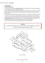
Page 26: ...Tecnichal Annex Furnace H3 List of parts Gas layout...

Page 27: ...A3 List of parts...

Page 28: ...A4 GAS FORGE H3...

Page 29: ...A5...

Page 30: ...A6 GAS FORGE H3...

Page 31: ...A7...

Page 32: ...A8 GAS FORGE H3...

Page 33: ...A9 Gas layout...

Page 34: ...N MANDREL PIPE BENDER HORIZONTAL PRESS BRAKE TWISTING SCROLL BENDING MACHINES HYDRAULIC PRESS BRAKES HYDRAULIC SHEAR MACHINES GAS FORGES IRON EMBOSSING MACHINES END WROUGHT IRON MACHINES BROACHING MAC...

Reviews: