background image

C

C

MF

MF   

   RT PACK

RT PACK

SERVICE

GUIDE

Gas & Electric 

Models

3rd Edition 

HEATING & A/C EQUIPMENT

NATIONAL

COMFORT

PRODUCTS

®

(800) 523-7138

ncpservice@nrac.com

www.nationalcomfortproducts.com

National Comfort Products

A Division of National Refrigeration and Air Conditioning Products, Inc.


Go Thru-the-Wall

Summary of Contents for CPG41838-U

Page 1: ...ric Models 3rd Edition HEATING A C EQUIPMENT NATIONAL COMFORT PRODUCTS 800 523 7138 ncpservice nrac com www nationalcomfortproducts com National Comfort Products A Division of National Refrigeration a...

Page 2: ...2...

Page 3: ...ications A B C D E Series Non Condensing Furnace Models Page 12 Gas Furnace Specifications U Series Non Condensing Furnace Models Page 13 Gas Furnace Specifications U Series Condensing Furnace Models...

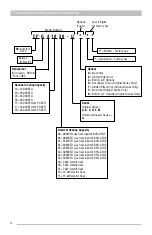
Page 4: ...at input 80 AFUE 64 64MBTU gas heat input 80 AFUE 25 25MBTU gas heat input 95 AFUE 32 32MBTU gas heat input 95 AFUE 43 43MBTU gas heat input 95 AFUE 50 50MBTU gas heat input 93 AFUE 03 3 kW electric h...

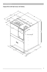
Page 5: ...5 Unit Dimensions Original R22 with Gas Heat A B Series 43...

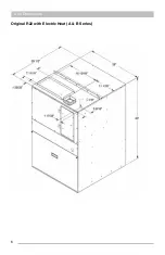
Page 6: ...6 Original R22 with Electric Heat A B Series Unit Dimensions...

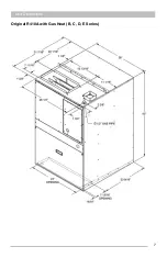
Page 7: ...7 Unit Dimensions Original R410A with Gas Heat B C D E Series...

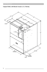
Page 8: ...8 Unit Dimensions Original R410A with Electric Heat B C D E Series...

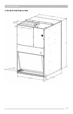
Page 9: ...9 Unit Dimensions U Series R410A 80 Gas Heat...

Page 10: ...10 Unit Dimensions U Series R410A up to 95 Gas Heat...

Page 11: ...11 Unit Dimensions U Series R410A Electric Heat...

Page 12: ...330 Specifications for A B C D E Series Non Condensing Furnaces Interlock Door Switch All CPG GAS MODELS come equipped with an interlock door switch This switch is located behind the bottom filter ac...

Page 13: ...Cold in w c 1 3 1 1 05 1 1 05 1 1 05 1 Presssure Hot in w c 95 05 8 05 8 05 8 05 Efficiency Range 80 5 81 5 81 5 82 5 81 5 82 5 80 1 81 1 Stack Temperature F 210 260 245 300 245 300 270 330 Specificat...

Page 14: ...en LED and waits indefinitely for the pressure switch to open If the pressure switch is open the control proceeds to 2 Pre purge 2 Pre purge The control energizes the venter motor and waits up to 240...

Page 15: ...ED will be de energized and the control will lockout for as long as the fault remains A hard lockout will automatically reset if the hardware fault clears Power Interruption During a momentary power i...

Page 16: ...ace Instructions for sliding out Non Condensing Furnace All Models manufactured after January 2015 feature a Slide Out Furnace 1 Remove the 4 screws indicated below Gas Furnace Gas Line Power Cord 2 R...

Page 17: ...Grasp the vertical heat exchanger partition firmly with your left hand 6 With your right hand reach under the burner box and lift the drain pan to release the drain plug Then lift up and pull the ass...

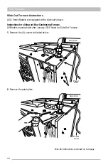
Page 18: ...18 Gas Furnace Instructions for Sliding Out Condensing Furnace 1 Remove the 2 screws indicated below 2 Remove the patch plate...

Page 19: ...19 Gas Furnace 3 Remove the 11 screws 4 Remove the front furnace baffle...

Page 20: ...lamp on the flue then proceed with sliding the furnace out Do Not Use Manifold as Handle Note Once removed the furnace should remain pitched toward the condensate collector box to keep condensate from...

Page 21: ...s the blower motor through the selected fan off delay Main Air High Temperature Limit Switch The Main Air limit Switch is used to protect the furnace heat exchanger from overheating most commonly due...

Page 22: ...differential setting Use an ohmmeter and verify there is no continuity across the terminals If you have verified that the limit switch has closed and the control board is still flashing 3 times see pa...

Page 23: ...000 30 400 55 40 F to 70 F 51 000 40 800 55 40 F to 70 F 64 000 51 200 65 55 F to 85 F U Series Non Condensing 28 000 22 400 52 5 45 F to 60 F 38 000 30 400 52 5 45 F to 60 F 51 000 40 800 55 45 F to...

Page 24: ...ollout Switch is located on top of the burner assembly with 2 screws It is wired in series with the main air high temperature limit switch Furnace Size Btuh 28k 38k 51k 64k Temperature Limit 5 F 225 F...

Page 25: ...ects the inducer from overheating due to lack of inducer airflow This switch breaks a circuit back to the DSI control board when tripped Furnace Size Btuh 25k 32k 43k 50k Temperature Limit 5 F 160 F 1...

Page 26: ...ndensing furnaces BTU Size 25K 32K 43K 50K Opens wc 9 05 9 05 9 05 7 05 0 55 WC On Condensing furnaces BTU Size 25K 32K 43K 50K Opens wc 9 05 9 05 9 05 7 05 Closes wc 1 05 Max 1 05 Max 1 05 Max 1 05 M...

Page 27: ...included the inducer motor which is powered by 208 230 volts ac from the DSI control board terminals IND and Neutral On non condensing models the inducer motor and wheel are removed from the housing...

Page 28: ...The inducer orifice is installed on the inlet of the inducer assembly and affects the overall system pressure To access the orifice you will need to remove the entire inducer assembly BTU Size 25K 32...

Page 29: ...nergized Internal control fault or no power FLAME STATUS YELLOW LED STEADY ON SLOW FLASH FAST FLASH Flame sensed Weak flame current below 1 0 microamps 50 Undesired flame valve open and no call for he...

Page 30: ...s factory set and is non ad justable If the setpoint is reached the flame rollout acts to interrupt the electric supply to the gas valve If the flame rollout switch activates identify and correct the...

Page 31: ...asing pressure is sensed in the All units are equipped with a temperature reset switch The flame rollout switch is the top of the burner assembly It is factor justable If the setpoint is reached the f...

Page 32: ...n both models the gas valve is located in the upper right hand section of the furnace For non condensing models the gas valve is a slow opening valve that is energized from a 24 volt signal sent from...

Page 33: ...iled The venter motor is forced off to open the pressure switch to stop gas flow unless a flame is present If the gas valve was sensed as closed when it should be open and has not de engerized after t...

Page 34: ...and the blower motor will run through the selected heat blower off delay time The control will do a soft lockout but will still respond to open limit and flame The FLAME yellow LED shall flash rapidly...

Page 35: ...ded to the furnace assembly or heat exchanger tube Burner Assembly On Non Condensing Models the burner is a single orifice ribbon style burner Furnace Size Btuh 28k 38k 51k 64k Orifice Size NG 39 31 2...

Page 36: ...g Furnaces Only The secondary heat exchanger is where condensate forms in a condensing furnace The furnace has different components that aid in the drainage of the secondary heat exchanger Gas Furnace...

Page 37: ...any drainage that occurs in the flue to pitch back to the collector box Drain Outlet Tubing There is a flexible drain tube that is connected to the outlet of the collector box This tube has a molded...

Page 38: ...that point the trap will drain completely It is important to keep the trap mounted in a vertical position at all times Since this is the primary trap used for drainage of the furnace it is also impor...

Page 39: ...the condensate drain for the cooling section IMPORTANT The furnace drain must be in a conditioned space and in some cases additional means for heating the drain line such as heat tape will be necessar...

Page 40: ...ll for Heat The thermostat sends a call for heat therefore energizing the white wire to the 1st contactor The 2nd contactor and 3rd if used will be powered after an adjustable time entry factory set f...

Page 41: ...heaters The high limit switch is normally closed opens at 175 F 5 F with an automatic reset differential of 40 F and is wired in series with the heater element To prove the high limit switch has faile...

Page 42: ...The slide out chassis can be field swapped with another chassis of similar capacity If a U series chassis is being installed into an older A B C D E or M series cabinet please make sure a Chassis Conv...

Page 43: ...nd must be removed Chassis Removal Instructions Remove the bottom filter access panel and control access panel Remove 4 screws and slide out air divider panel Disconnect both power and control molex p...

Page 44: ...e Speed Used on 1 1 5 Ton R410A B C Series 1 Ton units require with Smart Fan Control Blower bracket required for mounting 14270048 Electronically Commutated 1 3 HP 1120 RPM Multi Speed DC Control Boa...

Page 45: ...circuits to discharge Visually inspect the motor for any obstructions and carefully remove if any are found Turn the power back on to the motor and verify with a voltmeter the voltage at the line volt...

Page 46: ...46 Chassis Cooling Section...

Page 47: ...ack on to the motor and verify with a voltmeter the voltage at the line voltage connections from the motor leads Voltage should read between 197 252 volts Verify low voltage to the motor control using...

Page 48: ...ue 1 Red High 2 Yellow Med High 3 Blue Medium 4 Black Med Low 5 Orange Low Each speed tap is energized by a 24 Volt signal sent through a blower operation wire that originates at the DSI control board...

Page 49: ...once the chassis is slid out of the cabinet Follow this procedure on how to easily remove the blower assembly 1 Remove the 4 screws from the control deck and carefully slide all motor wiring through t...

Page 50: ...tors operate at 208 230 Volts AC Capacitor values for PSC motors 14270043 7 5 MFD 14270044 5 MFD 14270045 5 MFD PSC Motor with Smart Fan Control The Smart Fan Control is a Triac control board that low...

Page 51: ...ton 12 SEER U Series All Units Series including 9 2 EER U Series units draw air in across the coil and reject the heat from the condenser out the top grille All 12 SEER U Series units blow air across...

Page 52: ...minal and ground Verify the run capacitor charge in microfarads by measuring between HERM and COM terminals Do the same for the start capacitor if used When diagnosing a compressor that is operating d...

Page 53: ...the evaporator is 55 F which equals 155 psig of diaphragm pressure The evaporator pressure taken from the external equalizer line at the outlet of the evaporator is 110 psig This added to the spring t...

Page 54: ...Coremax valves R410A Superheat 8 12 F Subcooling 12 16 F SUCTION PRESSURE DISCHARGE PRESSURE SUPER HEAT SUBCOOLING POSSIBLE CONDITION LOW LOW LOW INSUFFICIENT AIR FLOW ACROSS EVAPORATOR COIL LOW LOW H...

Page 55: ...r coil Low pressure switch faults could be caused by one of the following Poor air flow Frozen coil Dirty coil Dirty or blocked filter Dirty blower Blower motor not operating System low on refrigerant...

Page 56: ...A drain pan is positioned underneath the evaporator coil to collect condensate A flexible tube included with the unit should be connected to the drain connection on the drain pan so it can be easily d...

Page 57: ...1 01 2003 to Current Day Position 1 Product Line 2 NCP Comfort Pack prior to 2007 After 01 01 2007 3 was used to indicate Comfort Pack Position 2 3 42 2002 43 2003 44 2004 45 2005 46 2006 47 2007 48 2...

Page 58: ...T SWITCH C F H CAP CFM C S R COMP EBM 208 230 C XFMER CC TRANSFORMER FACTORY SET POINT IS 230V FIELD ADJUSTMENT REQUIRED FOR 208V APPLICATION LOW MED HI TB ORANGE HEAT 38MBTU LOW 51MBTU MED 64MBTU HI...

Page 59: ...USTMENT REQUIRED FOR 208V APPLICATION LOW MED HI TB ORANGE HEAT 38MBTU LOW 51MBTU MED 64MBTU HI BLUE COOL 1 TON LOW 1 5 TON LOW 2 TON MED 2 5 TON HI SPEED CHART ORANGE BLUE BLUE RED BLACK YELLOW BROWN...

Page 60: ...08V APPLICATION BLUE BLUE RED BLACK YELLOW BROWN BLUE or ORANGE RED BLACK BLACK WHITE PURPLE BLACK BLACK ORANGE BLACK BLUE CB G R W C Y NEUTRALS COOL M1 EAC BLO HEAT L1 IND L1 3 AMP FUSE OK FLAME TEST...

Page 61: ...S 230V FIELD ADJUSTMENT REQUIRED FOR 208V APPLICATION LOW MED HI TB ORANGE BLUE BLUE RED BLACK YELLOW BROWN BLUE RED BLACK BLACK WHITE PURPLE BLACK HEAT SPEED COOL SPEED BLACK ORANGE BLACK BLUE CB G R...

Page 62: ...APPLICATION 1 2 3 4 5 SPEED TERMINAL 1 HIGH 2 MED HIGH 3 MED 4 MED LOW 5 LOW TB ORANGE HEAT 38MBTU 4 51MBTU 2 64MBTU 1 BLUE COOL 1 TON 5 1 5 TON 3 2 TON 2 2 5 TON 1 SPEED CHART ORANGE BLUE BLACK RED...

Page 63: ...ATION 1 2 3 4 5 SPEED TERMINAL 1 HIGH 2 MED HIGH 3 MED 4 MED LOW 5 LOW TB ORANGE HEAT 38MBTU 4 51MBTU 2 64MBTU 1 BLUE COOL 1 TON 5 1 5 TON 3 2 TON 2 2 5 TON 1 SPEED CHART ORANGE BLUE BLACK RED BLACK Y...

Page 64: ...TB ORANGE HEAT 28MBTU 5 38MBTU 4 51MBTU 2 64MBTU 1 BLUE COOL 1 TON 5 1 5 TON 3 2 TON 2 SPEED CHART ORANGE BLUE BLUE RED BLACK YELLOW BROWN BLUE YELLOW RED BLACK BLACK WHITE WHITE BLUE PURPLE BLACK BL...

Page 65: ...4 32MBTU 4 43MBTU 2 50MBTU 1 BLUE COOL 1 TON 5 1 5 TON 3 2 TON 2 SPEED CHART ORANGE BLUE BLUE RED BLACK BROWN BLUE YELLOW RED BLACK BLACK WHITE WHITE PURPLE BLACK WHITE RED YELLOW BLUE BLACK ORANGE H...

Page 66: ...WHITE WHITE M1 M2 M3 M4 24V COIL HL HL SEQ 230V COIL 3 2 1 6 5 4 GREEN ORANGE ORANGE C F H CAP CFM C S R COMP EBM 208 230 C XFMER CC TRANSFORMER FACTORY SET POINT IS 230V FIELD ADJUSTMENT REQUIRED FO...

Page 67: ...BLACK WHITE WHITE M1 M2 M3 M4 M1 M2 M3 M4 24V COIL HL HL HL SEQ 24V COIL 230V COIL WHITE 3 2 1 6 5 4 GREEN ORANGE ORANGE C F H CAP CFM C S R COMP EBM 208 230 C XFMER CC TRANSFORMER FACTORY SET POINT...

Page 68: ...WHITE WHITE BLACK BLACK BLACK WHITE GREEN BLACK WHITE WHITE M1 M2 M3 M4 24V COIL HL HL SEQ 230V COIL 3 2 1 6 5 4 GREEN ORANGE ORANGE C F H CAP CFM C S R COMP EBM 208 230 C XFMER CC TRANSFORMER FACTORY...

Page 69: ...ED BLACK BROWN BLUE RED BLACK BLACK WHITE PURPLE BLACK B L A C K HEAT SPEED COOL SPEED BLACK ORANGE BLACK BLACK HSD IF USED C F BROWN YELLOW F N L L SF IF USED B or C SERIES R410A 15KW SCHEMATIC WIRIN...

Page 70: ...L 3 2 1 6 5 4 1 2 3 4 5 TB WHITE RED YELLOW BLUE BLACK ORANGE HTR HTR FS WHITE WHITE WHITE BLACK BLACK BLACK BLACK WHITE WHITE M1 M2 M3 M4 24V COIL HL HL SEQ SPEED TERMINAL 1 HIGH 2 MED HIGH 3 MED 4 M...

Page 71: ...ERIES R410A 15KW SCHEMATIC WIRING DIAGRAM SERVICE MANUAL EDITION 3 17 2022 COMFORT PACK ELECTRIC NO NC C 1 6 2 TD 24V COIL 3 2 1 6 5 4 1 2 3 4 5 TB WHITE RED YELLOW BLUE BLACK ORANGE SPEED TERMINAL 1...

Page 72: ...N ORANGE ORANGE C F H CAP CFM C S R COMP EBM 208 230 C XFMER CC TRANSFORMER FACTORY SET POINT IS 230V FIELD ADJUSTMENT REQUIRED FOR 208V APPLICATION BLUE BROWN BLUE RED BLACK BLACK WHITE PURPLE BLACK...

Page 73: ...PEED COOL SPEED BLACK ORANGE BLACK HSD IF USED WHITE B L A C K E SERIES R410A 15KW SCHEMATIC WIRING DIAGRAM SERVICE MANUAL EDITION 3 17 2022 COMFORT PACK ELECTRIC TDOM C R DC DC R DC DC R FAN HS3 HS2...

Page 74: ...ON MAKE C F H CAP CFM C S R COMP EBM 208 230 C XFMER CC LPS TRANSFORMER FACTORY SET POINT IS 230V FIELD ADJUSTMENT REQUIRED FOR 208V APPLICATION 1 2 3 4 5 SPEED TERMINAL 1 HIGH 2 MED HIGH 3 MED 4 MED...

Page 75: ...LE BLACK BLUE BR BLOWER RELAY CAP DUAL CAPACITOR CC COMPRESSOR CONTACTOR CFM CONDENSER FAN MOTOR COMP COMPRESSOR EBM EVAPORATOR BLOWER MOTOR FS FUSE HC HEATER CONTACTOR LPS LOW PRESSURE SWITCH HL HIGH...

Page 76: ...R CONTACTOR WHITE RED YELLOW BLUE BLACK ORANGE HEAT SPEED COOL SPEED WHITE WHITE WHITE WHITE BLACK BLACK BLACK BLACK BLACK WHITE YELLOW BLUE ORANGE BLACK BLACK WHITE C W1A W1B W2 Y COOL HEAT CONTACTOR...

Page 77: ...EVAPORATOR BLOWER MOTOR FS FUSE HC HEATER CONTACTOR HL HIGH LIMIT SWITCH HTR ELECTRIC STRIP HEATER HPS HIGH PRESSURE SWITCH LPS LOW PRESSURE SWITCH XFMER TRANSFORMER TB TERMINAL BOARD WHITE RED YELLOW...

Page 78: ...ger Inspection 32 High Limit Switch 21 22 High Limit Switch Electric Heat 41 I Ignition Retry 15 Ignition Trial 14 Inducer Draft Motor 27 28 Interlock Door Switch 12 Interrupted Thermostat Call for He...

Page 79: ...79...

Page 80: ...G A C EQUIPMENT NATIONAL COMFORT PRODUCTS National Comfort Products A Division of National Refrigeration Air Conditioning Products Inc 539 Dunksferry Road Bensalem PA 19020 1 800 523 7138 ncpservice n...

Reviews: