USER MANUAL AND SPECIFICATIONS
NI cRIO-9074XT
Reconfigurable Embedded Chassis with Integrated Intelligent Real-
Time Controller for CompactRIO
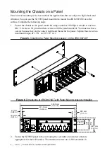
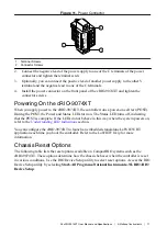
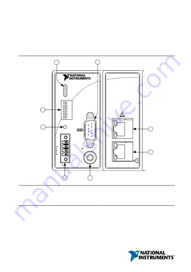
Figure 1.
CompactRIO cRIO-9074XT
NI cRIO-907x
1
3
5
2
4
6
7
8
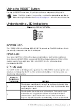
POWER
FPGA
STATUS
USER1
DO NOT
SEP
ARA
TE CABLES WHEN
ENERGIZED IN HAZARDOUS LOCA
TIONS
SAFE MODE
CONSOLE OUT
IP RESET
NO APP
USER1
NO FPGA
LINK
LINK
10/
100
10/
100
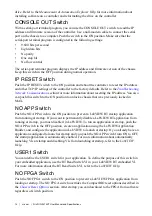
RESET
INPUT
19-30 V
20 W MAX
TRIGGER
V
C
NC
C
1. LEDs
2. RS-232 Serial Port
3. RJ-45 Ethernet Port 2
4. RJ-45 Ethernet Port 1
5. SMB Connector
6. Power Connector
7. Reset Button
8. DIP Switches
This document describes how to connect the cRIO-9074XT to a network and how to use the
features of the cRIO-9074XT.