
USER MANUAL
NI cRIO-9068
Reconfigurable Embedded Chassis with Integrated Intelligent Real-
Time Controller for CompactRIO
This document describes the features of the NI cRIO-9068 and contains information about
mounting and operating the device.
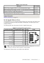
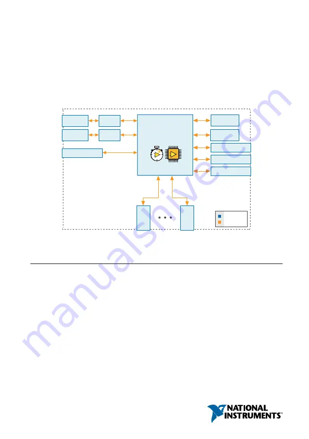
RJ-45
Ethernet2
RJ-45
Ethernet1
512 MB
DDR3
1 GB
NAND Flash
GigE
MAC/PHY
GigE
MAC/PHY
Xilinx Zynq-7020
XC7Z020
All-Programmable SoC
+
+
+
+
RGMII
RGMII
ONFI
NI cRIO-9068
Hardware
Data
C Ser
ies
Module
C Ser
ies
Module
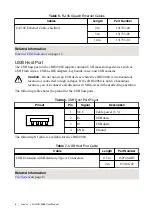
USB 2.0 Host Port
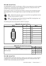
RS-232 Serial Port
RS-232 Serial Port
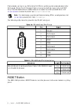
RS-485 Serial Port
Contents
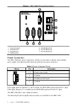
Ports and Connectors........................................................................................................ 3
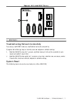
RESET Button...................................................................................................................8
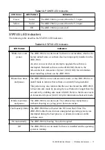
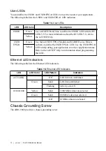
LEDs............................................................................................................................... 10
Chassis Grounding Screw............................................................................................... 12
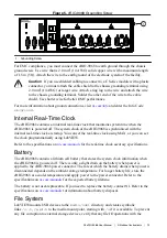
Internal Real-Time Clock................................................................................................13
Battery.............................................................................................................................13
File System......................................................................................................................13