
USER MANUAL
NI cRIO-9081
Reconfigurable Embedded Chassis with Integrated Intelligent Real-
Time Controller for CompactRIO
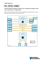
This document describes the features of the National Instruments cRIO-9081 and contains
information about mounting and operating the device.
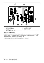
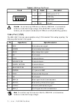
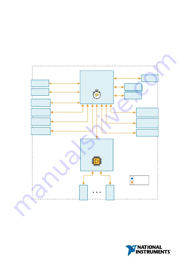
USB 2.0
Host Port
USB 2.0
Host Port
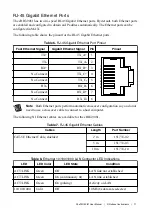
RJ-45 Gigabit
Ethernet Port 1
2 GB DDR3
16 GB
CFast SSD
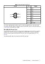
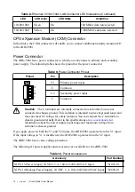
RS-232
Serial Port
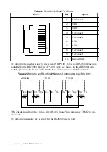
RJ-50
RS-485/422 (DTE)
Serial Port
MXI-Express Port
Intel Celeron
U3405 1.06 GHz Dual-Core
Processor
+
+
Xilinx Spartan-6
LX75 FPGA
+
+
cRIO-9081
Hardware
Data
C Ser
ies
Module
C Ser
ies
Module
VGA Port
USB 2.0
Host Port
USB 2.0
Host Port
RJ-45 Gigabit
Ethernet Port 2


