background image

OPERATING INSTRUCTIONS AND SPECIFICATIONS

NI 9155

Reconfigurable Embedded Chassis with Integrated MXI-Express (x1)
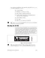
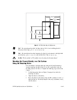
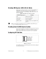
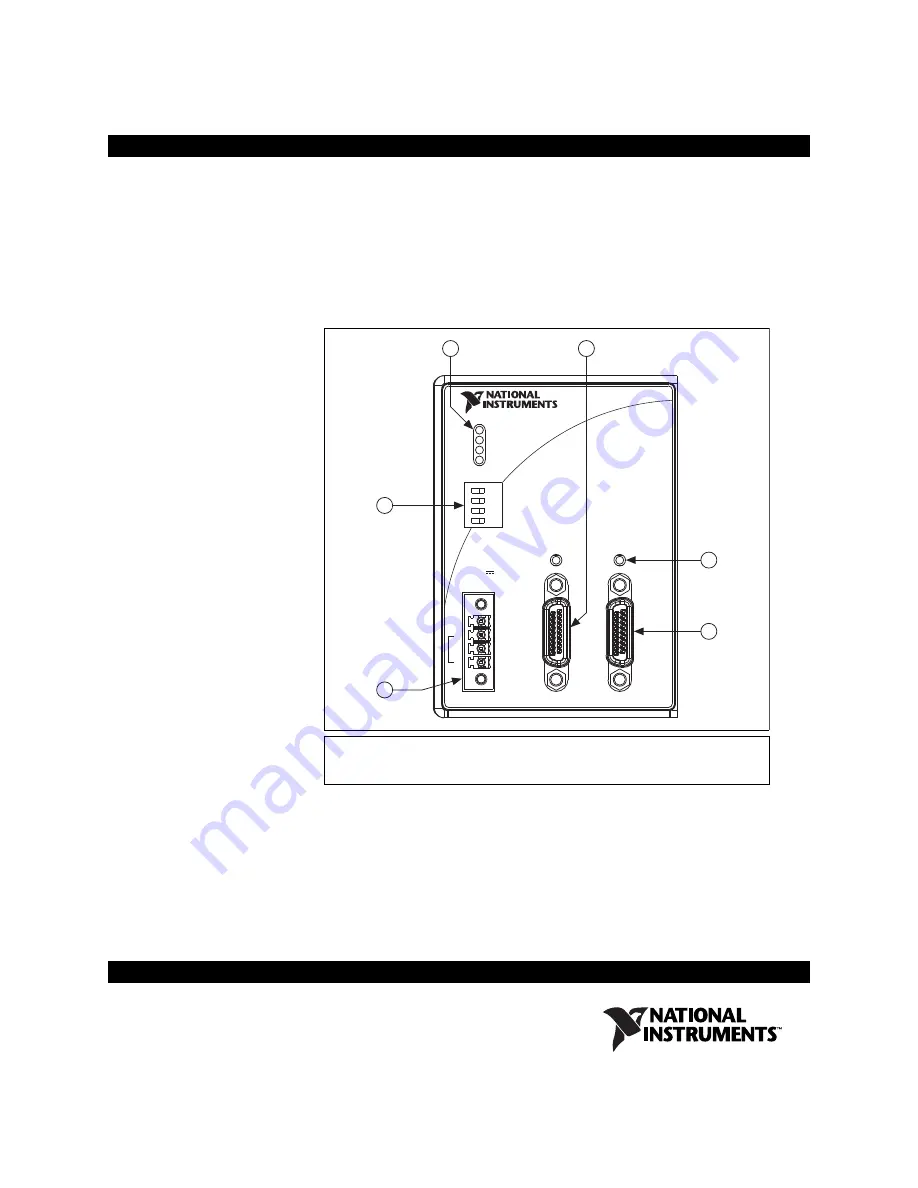
Figure 1.  

NI 9155 Front Panel

This document describes how to connect the NI 9155 to a MXI-Express 
host and one or more other chassis, and how to use the features of the 
NI 9155. This document also contains specifications for the NI 9155. This 
document refers inclusively to all reconfigurable embedded chassis with 
integrated MXI-Express (x1), such as the NI 9154, NI 9155, NI 9157, and 
NI 9159, as the NI 915x.

1

LEDs

2

Upstream Port

3

MXI-Express LINK LEDs

4

Downstream Port

5

Power Connector

6

DIP Switches

C

C

V2

V1

INPU

INPUT
9-30 V

9-30 V
25W MA

25W MAX

NO FPGA AP

NO FPGA APP
USER FPGA

USER FPGA1
USER FPGA

USER FPGA2
USER FPGA

USER FPGA3

P
USER FPGA

USER FPGA1
USER FPGA

USER FPGA2
USER FPGA

USER FPGA3

POWER

OWER

USER FPGA

USER FPGA1
USER FPGA

USER FPGA2
USER FPGA

USER FPGA3

LINK

LINK

LINK

LINK

UP

S

TREAM

S

TREAM

DO

WNS

TREAM

DO

WNS

TREAM

MXI-Express RIO

MXI-Express RIO

NI 9155

OFFOFF

3

2

4

5

6

1

Summary of Contents for NI 9155

Page 1: ...embedded chassis with integrated MXI Express x1 such as the NI 9154 NI 9155 NI 9157 and NI 9159 as the NI 915x 1 LEDs 2 Upstream Port 3 MXI Express LINK LEDs 4 Downstream Port 5 Power Connector 6 DIP...

Page 2: ...t IP 54 as defined by IEC 60529 and EN 60529 Special Conditions for Hazardous Locations Use in Europe Some chassis have been evaluated as Ex nA IIC T4 Gc equipment under DEMKO Certificate No 12 ATEX 1...

Page 3: ...pplications Some products are Lloyd s Register LR Type Approved for marine shipboard applications To verify Lloyd s Register certification for a product visit ni com certification and search for the L...

Page 4: ...NI 9155 Mounting the NI 9155 You can mount the chassis horizontally on a flat vertical metallic surface such as a panel or wall The maximum allowable ambient temperature for operation in this kind of...

Page 5: ...front of modules for cabling clearance for common connectors such as the 10 terminal detachable screw terminal connector as shown in Figure 3 Note For information about the minimum cabling clearance f...

Page 6: ...t Mounting the Chassis Directly on a Flat Surface Using the Mounting Holes For environments with high shock and vibration National Instruments requires mounting the chassis directly on a flat rigid su...

Page 7: ...on a DIN Rail Using the NI 9915 DIN Rail Mount Kit Complete the following steps to mount the chassis on a DIN rail using the NI 9915 DIN rail mount kit 1 Fasten the DIN rail clip to the chassis using...

Page 8: ...to the DIN Rail 3 Press down firmly on the chassis to compress the spring until the clip locks in place on the DIN rail Installing C Series I O Modules in the Chassis Figure 9 shows the mechanical dim...

Page 9: ...an be on when you install I O modules 2 Align the I O module with an I O module slot in the chassis as shown in Figure 10 The module slots are labeled 1 to 8 left to right Figure 10 Installing an I O...

Page 10: ...to 0 5 N m 4 4 lb in of torque 5 Attach the other end of the wire to earth ground using a method appropriate for the application Note If you use shielded cabling to connect to a C Series I O module wi...

Page 11: ...ensure that the voltage of that power supply measured at the chassis power connector is at least 500 mV higher than the voltage of the other power supply Caution The C terminals are internally connec...

Page 12: ...st detect all bus segments on the chassis side in order to configure the PCI hierarchy Powering connected chassis up or down while the host system is running can cause system hangs and data corruption...

Page 13: ...ring Down the MXI Express System Always power down the host system before powering down any connected NI 9155 chassis When the host system is powered down the order in which connected NI 9155 chassis...

Page 14: ...s of your application Refer to LabVIEW Help for information about programming these switches Understanding LED Indications Figure 12 NI 9155 LEDs POWER LED The POWER LED is lit while the NI 9155 is po...

Page 15: ...P48 slices 48 Available block RAM 3 456 kbits Timebases 40 80 120 160 or 200 MHz Accuracy 100 ppm max Frequency dependent jitter peak to peak 40 MHz 250 ps 80 MHz 422 ps 120 MHz 422 ps 160 MHz 402 ps...

Page 16: ...rminals 0 5 to 0 6 N m 4 4 to 5 3 lb in Chassis weight 1 600 g 56 4 oz Environmental Operating temperature IEC 60068 2 1 and IEC 60068 2 2 0 C to 55 C Note Refer to the mounting instructions in the Mo...

Page 17: ...s for measurements performed on circuits not directly connected to the electrical distribution system referred to as MAINS voltage MAINS is a hazardous live electrical supply system that powers equipm...

Page 18: ...follows 2006 95 EC Low Voltage Directive safety 2004 108 EC Electromagnetic Compatibility Directive EMC Online Product Certification Refer to Declaration of Conformity DoC for this product for additio...

Page 19: ...e DEMKO Ex nA IIC T4 Gc Where to Go for Support National Instruments corporate headquarters is located at 11500 North Mopac Expressway Austin Texas 78759 3504 National Instruments also has offices loc...

Page 20: ...ruments products technology refer to the appropriate location Help Patents in your software the patents txt file on your media or the National Instruments Patent Notice at ni com patents You can find...

Reviews: