
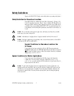

OPERATING INSTRUCTIONS AND SPECIFICATIONS
NI 9157/9159
Reconfigurable Embedded Chassis with Integrated MXI-Express (x1)
Figure 1.
NI 9157/9159
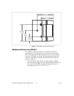
This document describes how to connect the NI 9157/9159 to a
MXI-Express host and one or more other chassis, and how to use
the features of the NI 9157/9159. This document also contains
specifications for the NI 9157/9159.
1
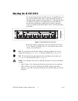
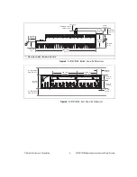
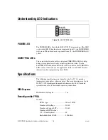
LEDs
2
Upstream Port
3
MXI-Express LINK LEDs
4
Downstream Port
5
Power Connector
6
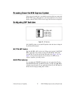
DIP Switches
4
6
2
5
1
C
C
V2
V1
INPUT
9-30 V
35W MAX
NO FPGA APP
USER FPGA1
USER FPGA2
USER FPGA3
P
USER FPGA1
USER FPGA2
USER FPGA3
POWER
USER FPGA1
USER FPGA2
USER FPGA3
LINK
LINK
UP
S
TREAM
DO
WNS
TREAM
MXI-Express RIO
NI 915X
3
OFF


