National Instruments PXI 1000B, User Manual
The National Instruments PXI 1000B is a high-performance chassis for PXI systems. Ensure proper setup and installation by downloading the Installation Manual for free from 88.208.23.73:8080. This manual provides step-by-step guidance on setting up your PXI 1000B for optimal performance.
Share
Download


Reviews:
No comments
Related manuals for PXI 1000B

KCT52A
Brand: Samsung Pages: 93

Megaplex II 4U Guide
Brand: American Megatrends Pages: 26

3C-MC-R16
Brand: 3C-Link Pages: 6
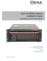
ValkyrieBay Val-C12-2400G
Brand: Xena Pages: 16

MASTER series
Brand: Turin Networks Pages: 36

Centillion 100
Brand: Bay Networks Pages: 10

SC745S2-800VB
Brand: Supermicro Pages: 104

Chassis SR1450
Brand: Intel Pages: 6

40-914-101
Brand: Pickering Pages: 26

3RAMPD017600
Brand: In Win Pages: 9
IW-RF100
Brand: In Win Pages: 15

101 TUF GAMING
Brand: In Win Pages: 15
IW-RS316-02M
Brand: In Win Pages: 20


