background image

Artisan Technology Group 

is your source for quality 

new and certified-used/pre-owned equipment

• 

FAST SHIPPING AND 

DELIVERY

• 

TENS OF THOUSANDS OF 

IN-STOCK ITEMS

•  EQUIPMENT DEMOS
• 

HUNDREDS OF 

MANUFACTURERS 

SUPPORTED

•  LEASING/MONTHLY


RENTALS

•  ITAR CERTIFIED


SECURE ASSET 

SOLUTIONS

SERVICE CENTER REPAIRS

Experienced engineers and technicians on staff 

at our full-service, in-house repair center

WE BUY USED EQUIPMENT

Sell your excess, underutilized, and idle used equipment 

We also offer credit for buy-backs and trade-ins

www.artisantg.com/WeBuyEquipment


REMOTE INSPECTION

Remotely inspect equipment before purchasing with 

our interactive website at


www.instraview.com

LOOKING FOR MORE INFORMATION? 

Visit us on the web at


www.artisantg.com


for more 

information on price quotations, drivers, technical 

specifications, manuals, and documentation

Contact us:


(888) 88-SOURCE  |  sales@artisantg.com  |  www.artisantg.com

SM

View

Instra

Summary of Contents for PXI-1011

Page 1: ... technicians on staff at our full service in house repair center WE BUY USED EQUIPMENT Sell your excess underutilized and id We also offer credit for buy backs and www artisantg com WeBuyEquipm REMOTE INSPECTION Remotely inspect equipment before purchasing with our interactive website at www instraview com LOOKING FOR MORE INFORMATION Visit us on the web at www artisant information on price quotat...

Page 2: ...p x I T M PXI 1011 Chassis User Manual Combination Chassis for PXI CompactPCl and SCXITMModules IWNATIONAL r INSTRUMENTS ...

Page 3: ...P x I T M PXI 1011ChassisUserManual CombinationChassisforPXI CompactPCl andSCXITMModules 111WrNATIONAL INSTRUMENTS February2000Edition PartNumber322592A 01 ...

Page 4: ...4 Germany 089 741 31 30 Greece 30 1 42 96 427 Hong Kong 2645 3186 India 91805275406 Israel 03 6120092 Italy 02 413091 Japan 03 5472 2970 Korea 02 596 7456 Mexico D F 5 280 7625 Mexico Monterrey 8 357 7695 Netherlands 0348 433466 New Zealand 09 914 0488 Norway 32 27 73 00 Poland 0 22 528 94 06 Portugal 351 1 726 9011 Singapore 2265886 Spain 91 640 0085 Sweden 08 587 895 00 Switzerland 056 200 51 51...

Page 5: ...the National Instruments installation operation or maintenance instructions owner s modification of the product owner s abuse misuse or negligent acts and power failure or surges fire flood accident actions of third parties or other events outside reasonable control Copyright Under the copyright laws this publication may not he reproduced or transmitted in any form electronic or mechanical includi...

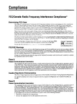
Page 6: ...mmission FCC and the Canadian Department of Communications DOC Changes or modifications not expressly approved by National Instruments could void the user s authority to operate the equipment under the FCC Rules ClassA FederalCommunicationsCommission This equipment has been tested and found to comply with the limits for a Class A digital device pursuant to part 15 of the FCC Rules These limits are...

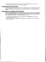
Page 7: ...rectives Readers in the EU EEC EEA must refer to the Manufacturer s Declaration of Conformity DoC for information pertaining to the CE Mark compliance scheme The Manufacturer includes a DoC for most every hardware product except for those bought for OEMs if also available from an original manufacturer that also markets in the EU or where compliance is not required as for electrically benign appara...

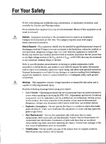
Page 8: ...s or injuries resulting from inadequate signal wire insulation incorrect signal connections or inadequate safety earth ground connections Warnings This equipment contains voltage hazardous to human life and safety and is capable of inflicting personal injury Read the following warnings before using your chassis L i v e Circuits Operating personnel and service personnel must not remove protective c...

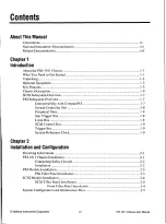
Page 9: ...em Reference Clock I 9 Chapter2 InstallationandConfiguration Mounting Information 2 1 PXI 1011 Chassis Installation 2 1 Connecting Safety Ground 2 2 Installation 2 2 PXI Module Installation 2 3 PXI Filler Panel Installation 2 3 SCXI Module Installation 2 4 SCXI Filler Panel Installation 2 4 Front Filler Panel Installation 2 4 System Configuration and Initialization Files 2 5 AboutThisManual Conven...

Page 10: ...icalSupportResources Glossary Index Figures Figure 1 1 F r o n t View of the PXI 1011Chassis 1 4 Figure 1 2 R e a r View of the PXI 1011Chassis 1 6 Figure 1 3 P X I Star Trigger and Local Bus Routing 1 9 Figure 2 1 Injector Ejector Handle Position during Module Insertion 2 3 Tables Table 1 1 P o w e r Cables 1 2 Table 1 2 P X I 1 0 1 1Chassis Front View Items 1 4 Table 1 3 P X I 1 0 1 1Chassis Rea...

Page 11: ... 2 P 2 J2 Connector Pin Assignments for the System Controller SlotB 2 Table B 3 P 1 J1 Connector Pin Assignments for the Star Trigger SlotB 3 Table B 4 P 2 J2 Connector Pin Assignments for the Star Trigger SlotB 4 Table B 5 P 1 J1 Connector Pin Assignments for the Peripheral Slot B 5 Table B 6 P 2 J2 Connector Pin Assignments for the Peripheral SlotB 6 NationalInstrumentsCorporation i x P X I 1 0 ...

Page 12: ...asis a cross reference or an introduction to a key concept This font also denotes text that is a placeholder for a word or value that you must supply monospace Text in this font denotes text or characters that you should enter from the keyboard sections of code programming examples and syntax examples This font is also used for the proper names of disk drives paths directories programs subprograms...

Page 13: ...sedocuments for hardware installation and configuration instructions specification information about your DAQ hardware and application hints Software documentation You might haveseveralsets of software documentation including LabVIEW LabWindows CVI and NI DAQ After you have set up your hardware system use either the application software LabVIEW or LabWindows CVI or the NI DAQ documentation to help...

Page 14: ... Y o u r computer technical reference manual If you are designing your own PXI module the following National Instruments specification available by request describes the physical electrical and timing requirements for PXI P X I Specification Revision 1 0 NationalInstrumentsCorporation x i i i P X I 1 0 1 1 ChassisUserManual ...

Page 15: ...ots integrate signal conditioning modules into your PXI system These modules provide analog and digital input conditioning isolation and other functions The PXI 1011 is ideal for applications where rack mount space is limited because it combines the computer plug in devices and signal conditioning modules in a single chassis You can daisy chain additional SCXI chassis to the PXI 1011 to build very...

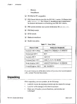
Page 16: ... Configuration for detailed information on initializing your PXI 1011chassis P X I system controller and system initialization file pxi sys ini P X I DAQ module SCXI module Flathead screwdriver Needle nose pliers Table 1 1 Power Cables If you are missing any of the above items or if you have the incorrect power cable contact National Instruments Unpacking While unpacking your new product do the fo...

Page 17: ...rmation about these products refer to your National Instruments catalog or contact the sales office nearest you KeyFeatures The PXI 101 I combines a high performance 4 slot PXI subsystem with an 8 slot SCXI subsystem The PXI 101 I has a structural design that is optimized for use in a wide range of applications The PXI 101 I fully complies with the PXI Specification Revision 1 0 offering advanced ...

Page 18: ...nsion Slots Connector 1 1 SCXI Subsystem Backplane 1 8 Injector Ejector Rail 5 SCXI High Voltage Analog Bus 1 2 PXI Subsystem Backplane Connector Item Description System Power Switch Turns the chassis on and off System Power Indicator LED When lit indicates that the chassis is on The PXI subsystem is always powered as long as the chassis is on SCXI Subsystem Power Indicator LED When lit indicates ...

Page 19: ... modules SCXI Subsystem Backplane Brings power control lines and low voltage analog bus connections to SCXI modules PXI Subsystem Backplane Brings CompactPCl 64 bit bus PXI trigger bus PXI star trigger bus and PXI local bus connections to PXI modules PXI Peripheral Slots Hold PXI peripheral modules PXI Star Trigger Slot Holds PXI star trigger controller or any PXI peripheral module PXI System Cont...

Page 20: ...ters Cool the chassis prevent dirt from contaminating the chassis circuitry SCXI Subsystem Power Switch Turns on off SCXI subsystem power when the chassis is on SCXI High Voltage Analog Bus Connector Connects to the high voltage analog bus on the SCXI high voltage backplane SCXI Auxilary I O Connector Connects to the control lines on the SCXI subsystem backplane SCXI Low Voltage Analog Bus Connect...

Page 21: ... chassis this way in addition to or instead of one of the first two methods The chassis address of a PXI 1011 chassis is hard wired as 0 PXISubsystemOverview The following sections describe the PXI subsystem InteroperabilitywithCompactPCl The PXI subsystem is interoperable with PXI compatible products and standard CompactPCl products This is an important feature because many PXI compatible systems...

Page 22: ...eral slot see Figure 1 3 and is intended for modules with Star Trigger functionality to provide individual triggers to all other peripherals However if youdo not require advanced trigger functionality you can install any standard peripheral module into this slot LocalBus The PXI backplane localbusis a daisy chainedbusthatconnectseach PXI peripheral slot with its adjacent left andright peripheral s...

Page 23: ...tion of several different PXI peripheral modules In other applications one module can control carefully timed sequences of operations performed on other modules in the system Modules can pass triggers to one another allowing precisely timed responses to asynchronous external events the system is monitoring or controlling SystemReferenceClock The PXI 1011 supplies the PXI 10 MHz system clock signal...

Page 24: ...clock The party implementing this option could be liable for any interference created by the clock and be required to take whatever measures are needed to eliminate interference to radio television and other wireless applications Such measures include switching off this device until other means are found to control the interference problem 400 Hz power applications The PXI 1011 can operate on 400 ...

Page 25: ...pper sections of the sides Place your PXI 1011 on a bench or in an instrument rack so that the fans air inlets and the air outlet apertures along both sides of the chassis have adequate ventilation Keep other equipment a minimum of 3 0 in 76 2 mm away from the air inlets and outlets Install your chassis for easy access to the rear panel This simplifies air filter replacement Rack mount application...

Page 26: ...install the PXI 1011 chassis 1 Place the PXI chassis on a sturdy level surface Leave at least 10 cm 4 in of space behind the chassis for adequate air circulation 2 Tu r n off the system power switch 3 Insert the female end of your power cable into the power entry module 4 Insert the male end of your power cable into the wall outlet 5 Install the SCXI and PXI modules into the chassis see the approp...

Page 27: ...he module to the rear of the chassis making sure that the injector ejector handle is pushed down as shown in Figure 2 1 3 W h e n you begin to feel resistance push up on the injector ejector handle to inject the module into the frame 4 Secure the module s front panel to the chassis using the module front panel mounting screws Figure2 1 Injector Ejector HandlePosition during Module Insertion PXIFil...

Page 28: ...le documentation for specific instructions pertaining to the module especially configuration and signal connections SCXIFillerPanelInstallation The SCXI front filler panel accessories protect the inside of the SCXI subsystem by preventing unwanted material from entering the PXI chassis and damaging modules or forming conductive paths that may degrade performance Install all SCXI modules first then...

Page 29: ...n file called pxisys ini The system controller manufacturer will either provide a pxi sys ini file for the particular chassis model that contains the system controller or provide a utility that can read an arbitrary chassis ini file and generate the corresponding pxisys ini file System controllers from National Instruments provide the pxisys ini file for the PXI 1011 chassis so that the user shoul...

Page 30: ...ection at the beginning of this document before attempting any procedures in this chapter Caution M a n y components within the chassis are susceptible to static discharge damage Service the chassis only in a static free environment Observe standard handling precautions for static sensitive devices while servicing the chassis Always wear a grounded wrist strap or equivalent while servicing the cha...

Page 31: ... while cleaning the chassis Do not use chemical cleaning agents they may damage the chassis Avoid chemicals that contain benzene toluene xylene acetone or similar solvents FanFilterCleaning To easily remove the chassis cooling filters from the rear of the chassis turn the power off and remove the plastic housing attached to each fan To clean the fan filters wash them in a mild soap solution and th...

Page 32: ...the circuit breaker trips again perform the following steps 1 Tu r n off the system power switch 2 Remove all modules from the chassis 3 Depress the circuit breaker to reset it 4 Tu r n on the system power switch and verify that the circuit breaker does not trip 5 Verify that your PXI 1011 can meet the power requirements of your CompactPCl or PXI modules Overloading the chassis can trip the breake...

Page 33: ...ics A CInput Input voltage range8 5 2 6 4 VAC Input frequency range4 7 to 440 Hz Over current protection5 A circuit breaker Operating current4 2 A at low power line AC to DC Power Conversion Efficiency7 0 typ D COutput Max usable power1 4 0 W PXI subsystem DC current capacity TableA 1 Maximum CurrentsAvailable toPXISubsystem NationalInstrumentsCorporation A 1 P X I 1 0 1 1 ChassisUserManual ...

Page 34: ...nt protectionC o n s t a n t current limiting at 140 150 of rated output Over voltage protection1 1 0 0 5V for each output Powersupply unit mean time between failure MTBF 1 0 0 0 0 0 h at 75 load and 25 C ambient temperature PXISubsystemCooling Perslot cooling capacityS l o t cooling capacity in worst case slot is 20 W Module cooling systemF o r c e d air circulation positive pressurization via tw...

Page 35: ...2 0 to 70 C Operating relative humidity 1 0 to 90 noncondensing Functional shock operating M I L T 28800E CLASS 3 Half Sine Shock Pulse II ms duration 30 g peak Random vibration operational 5 to 500 Hz 0 31gRms Random vibration non operational 1 0 to 500 Hz 2 46gRms Altitude2 km 1 24 mi I Random vibration profiles were developed in accordance with MIL T 28800E CLASS 3 and MIL STD 810E Method 514 T...

Page 36: ...I subsystem one system slot with three system expansion slots and three peripheral slots Compliant with IEEE 1101 10 mechanical packaging PXI Specification Revision 1 0 compliant Accepts both PXI and CompactPCl PICMG 2 0 R2 1 3U modules Backplane bare board materialU L 94 V 0 rated Backplane connectorsC o n f o r m to IEC 917 and IEC 1076 4 101 and are UL 94 V 0 rated Mechanical Overall dimensions...

Page 37: ... the P2 J2 Controller slot Table B 3 shows the PI J1 Trigger slot Table B 4 shows the P2 J2 Trigger slot Table B 5 shows the P1 J1 peripheral slots Table B 6 shows the P2 J2 peripheral slots Note P X I signals are shown in bold PI and P2 connector pin assignments for the connector pin assignments for the System connector pin assignments for the System connector pin assignments for the Star connect...

Page 38: ...5V TMS TDO TDI GND 1 GND 5V 12V TRST 12V 5V GND Pin Z A B C D E F 22 GND PXI_RSVA22 PXI_RSVB22 PXI_RSVC22 PXI_RSVD22 PXI_RSVE22 GND 21 GND RSV GND RSV RSV RSV GND 20 GND RSV RSV RSV GND RSV GND 19 GND RSV GND RSV RSV RSV GND 18 GND PXI_TRIG3 PXI_TRIG4 PX1 TRIGS GND PXI_TRIG6 GND 17 GND PXI_TRIG2 GND PRST REQ6 GNT6 GND 16 GND PXI_TRIG1 PXI_TRIGO DEG GND PXLTRIG7 GND 15 GND PXI_BRSVA15 GND FAL REQS ...

Page 39: ... GND 24 GND AD11 I 5V V I 0 AD 01 ACK64 GND 23 GND 3 3V AD141 AD 31 5V AD 2 GND 22 GND AD 71 GND 3 3V AD161 ADI51 GND 21 GND 3 3V ADP AD181 M66EN C BE 01 GND 20 GND AD 121 GND V I 0 A D M AD 101 GND 19 GND 3 3V AD 151 A131141 GND AD 131 GND 18 GND SERR GND 3 3V PAR C BE 1111 GND 17 GND 3 3V SDONE SBO GND PERR GND 16 GND DEVSEL GND V 1 0 STOP LOCK GND 15 GND 3 3V FRAME IRDY GND TRDY GND 12 14 Key A...

Page 40: ...RIG3 PXI_TRIG4 PXI_TRIG5 GND PXI TRIG6 GND 17 GND PXI_TRIG2 GND PRST PXI_CLK 10_IN PXI_CLK 10 GND 16 GND PXI TRIG1 PXI_TRIGO DEG GND PXI_TRIG7 GND 15 GND PXI_BRSVA15 GND FAL PX I_STA R6 PXI_LBR6 GND 14 GND AD 351 AD1341 AD 33 GND AD 321 GND 13 GND AD 381 GND V 1 0 AD 37 AD 361 GND 12 GND AD 421 AD 411 AD 40 GND AD 39 GND 1 1 GNI AD 45l GND V 1 0 AD 441 A131431 GND 10 GND AD 491 AD148 A131471 GND A...

Page 41: ...31 GND 18 GND SERR GND 13V PAR C BE11Itt GND 17 GND 3 3V SDONE SBO GND PERR GND 16 GND DEVSEL GND V U0 STOP LOCK GND 15 GND 3 3V FRAME IRDY GND TRDY GND 12 14 Key Area 11 GND AD 18 ADII71 AD 16 GND C BE 2I GND 10 GND AD 21 GND 3 3V A D 201 AD 191 GND 9 GND C BEI31 IDSEL AD 231 GND A D 22 GND 8 GND AD 26 GND V I 0 A D 25I AD 24I GND 7 GND ADI301 AD 291 AD 28 GND AD 27I GND 6 GND REQ GND 3 3V CLK AD...

Page 42: ...331 GND AD 32 GND 13 GND AD138 GND V I O AD 37 AD 361 GND 12 GND AD1421 AD 41 AD1401 GND AD 391 GND 11 GND AD 45 GND V 1 0 AD 44 AD 43 GND 10 GND AD1491 AD 48 AD 471 GND AD 461 GND 9 GND AD 52 GND V 1 0 AD 51 AD 501 GND 8 GND AD 56 AD 551 AD 54 GND AD 53 GND 7 GND AD1591 GND V 1 0 AD 58 AD 57I GND 6 GND AD 63 AD 62 AD 61 GND AD 60 GND 5 GND C BE151 GND V I 0 C BE 41 PAR64 GND 4 GND V I 0 PXI_BRSVB...

Page 43: ...ections devoted to our newest products The database is updated daily in response to new customer experiences and feedback Troubleshooting Wizards Step by step guides lead you through common problems and answer questions about our entire product line Wizards include screen shots that illustrate the steps being described and provide detailed information ranging from simple getting started instructio...

Page 44: ...se Web sites from www ni com worldwide If you have trouble connecting to our Web site please contact your local National Instruments office or the source from which you purchased your National Instruments product s to obtain support For telephone support in the United States dial 512 795 8248 For telephone support outside the United States contact your local branch office Australia 03 9879 5166 Au...

Page 45: ...t of current AC a l t e r n a t i n g current ANSI A m e r i c a n National Standards Institute asynchronous timing 1 Hardware a property of anevent that is not synchronized to a reference clock 2 Software a property of a function that begins an operation and returns before the operation is complete AWG A m e r i c a n Wire Gauge NationalInstrumentsCorporation 6 1 P X I 1 0 1 1 ChassisUserManual ...

Page 46: ...omponent Interconnect PCI Specification 2 1 or later for industrial and or embedded applications requiring a more robust mechanical form factor than desktop PCI It uses industry standard mechanical components and high performance connector technologies to provide an optimized system intended for rugged applications It is electrically compatible with the PCI Specification which enables low cost PCI...

Page 47: ... m s2 GND g r o u n d signal GPIB G e n e r a l Purpose Interface Bus IEEE 488 gRMS A measure of random vibration The root mean square of acceleration levels in a random vibration test profile H h h o u r Hz h e r t z cycles per second IEC I n t e r n a t i o n a l Electrotechnical Commission an organization that sets international electrical and electronics standards IEEE I n s t i t u t e of Ele...

Page 48: ...F m e a n time between failure MTTR m e a n time to repair N NEMA N a t i o n a l Electrical ManufacturersAssociation 0 overcurrent W h e n the load on a power supplydraws more current than what the power condition s u p p l y is rated for P PXI P C I eXtensions for Instrumentation PXI_CLK1 0 T h e pin that provides the PXI 10 MHz system clock signal to a peripheral slot PXI 1011ChassisUserManual ...

Page 49: ...t i v e humidity RMS r o o t mean square a method used to measure electrical output in volts and watts S s s e c o n d s SCXI SCXI stands for Signal Conditioning eXtensions for Instrumentation and is a National Instruments product line designed to perform front end signal conditioning for National Instruments plug in DAQ devices SCXI subsystem T h e PXI 1011 chassis section that uses SCXI modules ...

Page 50: ...a PXIbus mainframe This device is unique in the PXIbus system in that it performs the VMEbus system controller functions including clock sourcing and arbitration for data transfers across the backplane Installing such a device into any other slot can damage the device the PXIbus backplane or both trigger A n y event that causes or starts some form of data capture TTL t r a n s i s t o r transistor...

Page 51: ...cumentation xiii E environmental specifications A 3 equipment optional 1 3 F fans and filters filter cleaning procedures 3 2 PXI subsystem cooling specifications A 2 to A 3 rear view of PXI 1011 figure 1 6 filler panel installation PXI subsystem 2 3 SCXI subsystem 2 4 ground connection 2 2 initialization files 2 5 installation configuration and initialization files 2 5 mounting information 2 1 PXI...

Page 52: ...3 to B 4 System Controller slot table B 1 to B 2 P2 J2 connector pin assignments peripheral slot table B 6 Star Trigger slot table B 4 to B 5 System Controller slot table B 2 to B 3 peripheral slots description 1 8 PI J1 connector pin assignments table B 5 to B 6 P2 J2 connector pin assignments table B 6 parts locator diagram 1 4 power cables table 1 2 power failure troubleshooting table 3 3 probl...

Page 53: ...slot for PXI peripheral module 1 9 installation filler panel installation 2 4 procedure 2 4 overview 1 7 software related resources C 2 specifications A I to A 4 backplane A 4 compliance A 4 environmental A 3 mechanical A 4 PXI subsystem cooling A 2 to A 3 PXI subsystem electrical characteristics A 1 to A 2 safety characteristics A 3 Star Trigger slot description 1 8 P1 J1 connector pin assignment...

Page 54: ...Web support from National Instruments C 1 to C 2 online problem solving and diagnostic resources C 1 software related resources C 2 Worldwide technical support C 2 PX1 101 1ChassisUserManual 1 4 w w w n i c o m ...

Page 55: ... technicians on staff at our full service in house repair center WE BUY USED EQUIPMENT Sell your excess underutilized and id We also offer credit for buy backs and www artisantg com WeBuyEquipm REMOTE INSPECTION Remotely inspect equipment before purchasing with our interactive website at www instraview com LOOKING FOR MORE INFORMATION Visit us on the web at www artisant information on price quotat...

Reviews: