


Reviews:
No comments
Related manuals for PXI-1036DC

HTCA-6200
Brand: Lanner Pages: 81

Echo Express SEL
Brand: Sonnet Pages: 16

Echo Express III-D
Brand: Sonnet Pages: 18

ONErack 1RK-5RU-KIT
Brand: Tvone Pages: 8

Racal Instruments 1264C
Brand: Eads Pages: 100

IPC-3026
Brand: Advantech Pages: 30

HPC-7484
Brand: Advantech Pages: 32
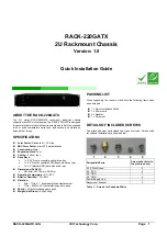
RACK-220GATX
Brand: IEI Technology Pages: 8


