background image

USER MANUAL

PXIe-1086DC

PXIe, 18-Slot (16 Hybrid Slots, 1 PXI Express Slot), Up to 12 GB/s
PXI Chassis

The manual includes instructions for installing and configuring your PXIe-1086DC chassis
and PXI Express system.

Contents

Getting Started.......................................................................................................................... 2

Unpacking......................................................................................................................... 2
What You Need to Get Started..........................................................................................2
Key Features..................................................................................................................... 2
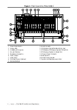
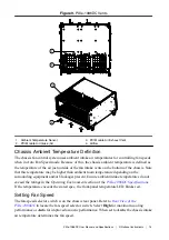
Chassis Description...........................................................................................................3
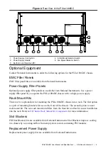
Optional Equipment.......................................................................................................... 5
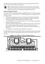
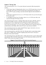
PXIe-1086DC Chassis Backplane Overview....................................................................6

Installation and Configuration................................................................................................ 12

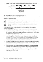
Safety Information.......................................................................................................... 12
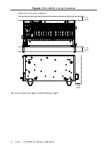
Chassis Cooling Considerations......................................................................................13
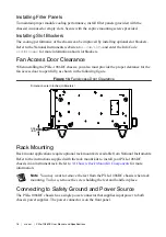
Fan Access Door Clearance............................................................................................ 16
Rack Mounting................................................................................................................16
Connecting to Safety Ground and Power Source............................................................16
Power-On Test.................................................................................................................18
Installing a PXI Express System Controller................................................................... 18
Installing Peripheral Modules......................................................................................... 20
Remote System Monitoring............................................................................................ 21
LED Indicators................................................................................................................22
Remote Inhibit and Fault Monitoring............................................................................. 24
Inhibit Mode Switch........................................................................................................24
PXI_CLK10 Front Panel Connectors............................................................................. 25
PXI Express System Configuration with MAX..............................................................25
Using System Configuration and Initialization Files......................................................27

Maintenance............................................................................................................................ 28

Service Interval............................................................................................................... 28
Preparation...................................................................................................................... 28

Summary of Contents for PXIe-1086DC

Page 1: ...6 Installation and Configuration 12 Safety Information 12 Chassis Cooling Considerations 13 Fan Access Door Clearance 16 Rack Mounting 16 Connecting to Safety Ground and Power Source 16 Power On Test...

Page 2: ...amage to the metal work Check to make sure all handles hardware and switches are undamaged Inspect the inner chassis for any possible damage debris or detached components If damage appears to have bee...

Page 3: ...ternal 100 MHz reference clock for PXI Express slots with 25 ppm stability Variable speed fan controller optimizes cooling and acoustic emissions Remote power inhibit control Complies with PXI and Com...

Page 4: ...Backplane Connectors 6 Clk10 Output 7 Clk10 Input 8 PXI Filler Panels Optional 9 Removable Feet 10 Fan Door Latch 11 PXI Express Hybrid Peripheral Slots 16x 12 PXI Express PXI Express System Timing Sl...

Page 5: ...a single power supply Rack Mount Kits There are two optional kits for mounting the PXIe 1086DC chassis into a rack The first option is a pair of mounting brackets for use on the front of the chassis T...

Page 6: ...Ie 1086DC PCI Express Backplane Diagram System slot link 1 is a Gen 2 x8 PCI Express link to PCI Express switch 1 providing a nominal bandwidth of 4 GB s single direction between the system controller...

Page 7: ...s switch to the system slot A hybrid compatible PXI Peripheral module modified by replacing the J2 connector with an XJ4 connector installed in the upper eight rows of J2 Refer to the PXI Express Spec...

Page 8: ...s for high speed triggering synchronization and clocking Refer to the PXI Express Specification for details The system timing slot also has a single ended PXI Star trigger connected to every slot Refe...

Page 9: ...er lines from adjacent PXI trigger bus segments can be routed in either direction across the PXI trigger bridges through buffers This allows you to send trigger signals to and receive trigger signals...

Page 10: ...h the PXI_CLK10_IN pin on the System Timing Slot Refer to the System Timing Slot XP4 Connector Pinout section for the pinout When a 10MHz clock is detected on this pin the backplane automatically phas...

Page 11: ...nchronous to PXI_CLK10 The frequency of PXIe_SYNC100 is 10 n MHz where n is a positive integer The default for n is 1 giving PXIe_SYNC100 a 100 ns period However the backplane allows n to be programme...

Page 12: ...Live Circuits Operating personnel and service personnel must not remove protective covers when operating or servicing the chassis Adjustments and service to internal components must be undertaken by...

Page 13: ...is not a supported configuration Regardless of the configuration you must provide the cooling clearances as outlined in the following sections Providing Adequate Clearance The primary cooling exhaust...

Page 14: ...1086DC Cooling Clearances 1 75 44 5 3 00 76 2 Dimensions are in inches millimeters 1 75 44 5 PXIe 1086DC H The vent locations are shown in the following figure 14 ni com PXIe 1086DC User Manual and S...

Page 15: ...r than ambient room temperature depending on the surrounding equipment and or blockages present Ensure ambient intake temperatures do not exceed the ratings in the Operating Environment section of the...

Page 16: ...n in the following figure Figure 10 Fan Access Door Clearance Dimensions are in inches millimeters 0 35 8 9 Rack Mounting Rack mount applications require optional rack mount kits available from Nation...

Page 17: ...t en toute s curit le ch ssis PXIe 1086DC doit disposer d un fil de protection mise la terre reli par l installateur au syst me de mise la terre du site Le cordon d alimentation fourni dispose d un fi...

Page 18: ...t the Inhibit Mode switch on the back of the chassis to the Manual position Observe that all fans become operational and that all chassis LEDs are steady green Set the Inhibit Mode switch back to the...

Page 19: ...r front panel mounting screws 4 Connect the keyboard mouse and monitor to the appropriate connectors Connect devices to ports as required by your system configuration 5 Power on the chassis Verify tha...

Page 20: ...to your peripheral module user manual for specific instructions and warnings To install a module complete the following steps 1 Ensure that the chassis is properly grounded to protect it from electri...

Page 21: ...e whether your network supports DHCP If your network uses DHCP the network configuration is performed automatically Refer to Front View of the PXIe 1086DC to locate the Ethernet port To use the remote...

Page 22: ...te is selected Steady green 100 Mbps data rate is selected Default Configuration Settings The chassis ships from the factory with the following default configuration settings DHCP with Auto IP fallbac...

Page 23: ...ns have failed and chassis must shut itself down Power Supply 1 Status Off Power supply is not installed or is in standby Steady green Power supply is active and all voltages are within normal operati...

Page 24: ...k on the chassis front panel Refer to Front View of the PXIe 1086DC to locate this connector Table 6 Remote Inhibit and Fault Connector Pinout Pin Signal 1 Remote Inhibit active low 2 Ground 3 Remove...

Page 25: ...MA connectors on the front of the PXIe 1086DC chassis for PXI_CLK10 The connectors are labeled IN and OUT You can use them for supplying the backplane with PXI_CLK10 or routing the backplane s PXI_CLK...

Page 26: ...mmends dynamic reservations and routing are used whenever possible If static reservations are required static reservation of trigger lines can be implemented by the user in MAX through the Triggers ta...

Page 27: ...Triggers tab near the bottom 3 For each trigger line select Route Right Route Outward From Middle or Route Left to route triggers on that line in the described direction or select Disabled for the def...

Page 28: ...er to the PXI Express specification at www pxisa org Maintenance This section describes basic maintenance procedures you can perform on the PXIe 1086DC chassis Caution Disconnect the power cable prior...

Page 29: ...nd install a modular power supply for the PXIe 1086DC chassis Caution Disconnect the power cable prior to replacing the power supply Attention D branchez le c ble d alimentation avant de remplacer le...

Page 30: ...1 Disengage the two screws on the rear of the power supply with a flat blade screwdriver 2 Extend the collapsible handle and pull the power supply out of the chassis Figure 18 Removing Power Supply f...

Page 31: ...captive screws with a flat blade screwdriver until the threads disengage from the chassis frame 3 Rotate the drawer levers to eject the drawer from the chassis frame 4 Pull the drawer about halfway ou...

Page 32: ...r supplies by removing the entire power drawer from the chassis The power drawer is shown in PXIe 1086DC Power Drawer Caution If you are using the PXIe 1086DC and SC Express modules with front mountin...

Page 33: ...ssis Before attempting to replace a fan assembly verify that there is adequate clearance in front of the chassis The fans for this chassis are redundant and hot swappable You can remove the fans with...

Page 34: ...atch until it disengages and allows removal by pulling the fan module forward Installation Ensure there is no visible damage to the new fan assembly before installing it Verify that there is no foreig...

Page 35: ...o 63 Hz Efficiency 70 typical Power disconnect The AC DC power cable provides main power disconnect Do not position the equipment so that it is difficult to disconnect the power cord The front panel p...

Page 36: ...Slot 15 A 15 A 30 A 1 A System Timing Slot 6 A 4 A 1 A Hybrid Peripheral Slot with PXI 1 Peripheral 6 A 5 A 6 A 1 A 1 A Hybrid Peripheral Slot with PXI 5 Peripheral 6 A 4 A 1 A PXI 1 Peripheral Slot...

Page 37: ...ge Power supply shuttle MTTR Replacement in under 1 minute Chassis Cooling Module cooling system Forced air circulation positive pressurization through six 150 cfm fans three sets of dual stacked fans...

Page 38: ...ondensing Storage Environment Ambient temperature range 40 C to 71 C Relative humidity range 5 to 95 noncondensing Shock and Vibration Operational shock 30 g peak half sine 11 ms pulse Random Vibratio...

Page 39: ...s Conforms to IEC 917 and IEC 1076 4 101 UL 94 V 0 rated 10 MHz System Reference Clock PXI_CLK10 Maximum slot to slot skew 250 ps Accuracy 25 ppm max guaranteed over the operating temperature range Ma...

Page 40: ...o 50 2 VPP unloaded Output impedance 50 5 External Clock Source Frequency 10 MHz 100 ppm Input amplitude Front panel SMA 200 mVPP to 5 VPP square wave or sine wave System timing slot PXI_CLK10_IN 5 V...

Page 41: ...power supply 31 5 lb 14 3 kg Chassis materials Sheet Aluminum 5052 H32 3003 H14 and 6061 T6 Extruded Aluminum 6060 T6 and Cold Rolled Steel PC ABS Santoprene Nylon Finish Conductive Clear Iridite on...

Page 42: ...12 7 17 50 444 5 0 39 9 9 1 84 46 8 8 73 221 9 2 09 53 2 1 23 31 3 10 70 271 8 1 82 46 3 1 82 46 3 1 84 46 8 3 54 90 0 5 57 141 5 0 84 21 3 0 75 19 1 2 13 54 2 10 10 256 1 17 80 452 7 14 35 364 40 NI...

Page 43: ...Figure 22 PXIe 1086DC Chassis Dimensions Bottom Dimensions are in inches millimeters 0 18 4 7 PXIe 1086DC User Manual and Specifications National Instruments 43...

Page 44: ...tory use IEC 61010 1 EN 61010 1 UL 61010 1 CSA C22 2 No 61010 1 Note For UL and other safety certifications refer to the product label or the Product Certifications and Declarations section Electromag...

Page 45: ...nce information To obtain product certifications and the DoC for NI products visit ni com product certifications search by model number and click the appropriate link Environmental Management NI is co...

Page 46: ...2PERp4 2PERn4 GND 2PETp5 2PETn5 GND 4 2PETp6 2PETn6 GND 2PERp6 2PERn6 GND 2PERp5 2PERn5 GND 5 2PETp7 2PETn7 GND 2PERp7 2PERn7 GND 2PETp8 2PETn8 GND 6 2PETp9 2PETn9 GND 2PERp9 2PERn9 GND 2PERp8 2PERn8...

Page 47: ...PETn4 GND 8 1PETp5 1PETn5 GND 1PERp5 1PERn5 GND 1PERp4 1PERn4 GND 9 1PETp6 1PETn6 GND 1PERp6 1PERn6 GND 1PETp7 1PETn7 GND 10 2PETp0 2PETn0 GND 2PERp0 2PERn0 GND 1PERp7 1PERn7 GND System Controller Slo...

Page 48: ...4 B14 GND 10 A6 A6 GND B15 B15 GND A15 A15 GND PXIe_DSTAR System Timing Slot TP2 Connector Pinout Pin A B ab C D cd E F ef 1 C0 C0 GND C8 C8 GND B8 B8 GND 2 A0 A0 GND C9 C9 GND A8 A8 GND 3 B0 B0 GND C...

Page 49: ...1PETn5 GND 1PERp5 1PERn5 GND 1PERp4 1PERn4 GND 9 1PETp6 1PETn6 GND 1PERp6 1PERn6 GND 1PETp7 1PETn7 GND 10 RSV RSV GND RSV RSV GND 1PERp7 1PERn7 GND PXIe_ PXIe_DSTAR System Timing Slot XP4 Connector Pi...

Page 50: ...B_SDA GND PERR GND 16 GND DEVSEL GND V I O STOP LOCK GND 15 GND 3 3V FRAME IRDY BD_SEL TRDY GND 12 to 14 Key Area 11 GND AD 18 AD 17 AD 16 GND C BE 2 GND 10 GND AD 21 GND 3 3V AD 20 AD 19 GND 9 GND C...

Page 51: ...rtification If your product supports calibration you can obtain the calibration certificate for your product at ni com calibration National Instruments corporate headquarters is located at 11500 North...

Page 52: ...ments EULAs and third party legal notices in the readme file for your NI product Refer to the Export Compliance Information at ni com legal export compliance for the NI global trade compliance policy...

Reviews: